Language selection

Search

Patent 1297512 Summary

Third-party information liability

Some of the information on this Web page has been provided by external sources. The Government of Canada is not responsible for the accuracy, reliability or currency of the information supplied by external sources. Users wishing to rely upon this information should consult directly with the source of the information. Content provided by external sources is not subject to official languages, privacy and accessibility requirements.

Claims and Abstract availability

Any discrepancies in the text and image of the Claims and Abstract are due to differing posting times. Text of the Claims and Abstract are posted:

  • At the time the application is open to public inspection;
  • At the time of issue of the patent (grant).
(12) Patent: (11) CA 1297512
(21) Application Number: 554688
(54) English Title: GOB DISTRIBUTOR
(54) French Title: DISTRIBUTEUR DE REMBLAI
Status: Expired
Bibliographic Data
(52) Canadian Patent Classification (CPC):
  • 270/184
(51) International Patent Classification (IPC):
  • C03B 7/14 (2006.01)
  • C03B 7/16 (2006.01)
(72) Inventors :
  • DUGA, ROBERT J. (United States of America)
(73) Owners :
  • EMHART GLASS S.A. (Switzerland)
(71) Applicants :
(74) Agent: NORTON ROSE FULBRIGHT CANADA LLP/S.E.N.C.R.L., S.R.L.
(74) Associate agent:
(45) Issued: 1992-03-17
(22) Filed Date: 1987-12-17
Availability of licence: N/A
(25) Language of filing: English

Patent Cooperation Treaty (PCT): No

(30) Application Priority Data:
Application No. Country/Territory Date
018,143 United States of America 1987-02-24

Abstracts

English Abstract


ABSTRACT


GOB DISTRIBUTOR


A gob distributor is disclosed having a head
including at least one gob scoop having a pinion and a
rack for interconnecting with the pinion so that the gob
scoop can be rotatively displaced through a
predetermined angular range. The rack is displaced by a
ball screw assembly wherein a vertically oriented forked
link having a bottom end and two vertically spaced top
ends connects the rack to the ball screw nut. Each of
the top ends is secured to ball screw nut so that the
link can be reoriented relative to the ball screw nut

about a vertical axis passing through the top ends to
compensate for misalignment between the ball screw and
the link and the bottom end is connected to the rack so
that any out of parallelism in either a horizontal or a
vertical plane between the link and the rack will be
accommodated.


Claims

Note: Claims are shown in the official language in which they were submitted.


The embodiments of the invention in which an
exclusive property or privilege is claimed are
defined as follows:
1. A gob distributor comprising
a head including at least one gob scoop
having a pinion and a rack for interconnecting with
said pinion so that said gob scoop can be rotatively
displaced through a predetermined angular range;
means for displacing said rack including
a ball screw,
a ball screw nut,
a vertically oriented forked link
having a bottom end and two vertically spaced top
struts,
means for securing the top end of each of
said top struts to said ball screw nut so that said
link can be reoriented relative to said ball screw

nut about a vertical axis passing through said top
ends to compensate for misalignment between said ball
screw and said link and
means for securing said bottom end to said
rack so that any out of parallelism in either a
horizontal or vertical plane between said link and
said rack will be accommodated, said struts being
selectively spaced to clear said ball screw
throughout its displacement range.


2. A gob distributor according to claim 1
where each of said top ends of the link has a
horizontally extending thru-hole therein and said
means for securing said top ends of the link each
comprises:


-6-


a wedge element having a sleeve portion for
insertion into one of said thru-holes and a wedge
portion having a bearing surface,
a bearing surface associated with said wedge
element bearing surface,
bolt means extending freely through said
wedge elements and said link thru-holes and threadingly
received by said ball screw nut.

3. A gob distributor according to claim 2,
wherein said means for securing said bottom link end to
said rack comprises:
a secured plate on one side of said link,
a wedge plate on the other side of said
link,
vertically spaced screw means extending
through link thru apertures for interconnecting said
plates,
said link thru apertures being larger than
said screw means whereby said plates can be reoriented
about a horizontal axis.

-7-

Description

Note: Descriptions are shown in the official language in which they were submitted.


~Z9'^~12

-- 1 --
GOB DISTRIBUTOR
SPECIFICATION
The present invention relates to mechanisms
for distributing glass gobs received from a gob
feeder -to discrete glassware forming stations.
Gob distributors include a head which
usually includes a plurality of gob scoops which can
be selectively rotated by displacing a rack which
interconnects with a pinion secured to each gob
scoop. The rack may be displaced by a servo driven
ball screw assembly. In such an arrangement there
may be some misalignment between the rack and the
ball screw and such misalignment will impose unwanted
stresses on the feed system.
It is accordingly an object of the present
invention to provide a coupling for linking the rack
to the ball screw assembly which will compensate for
any misalignment between the rack and the ball screw.
According to the above objects, from a
broad aspect, the present invention provides a gob
distributor which comprises a head including at least
one gob scoop having a pinion and a rack for
interconnecting with the pinion so that the gob scoop
can be rotatively displaced through a predetermined
angular range. Means is provided for displacing the
rack and includes a ball screw, a ball screw nut, a
vertically orien-ted forked link having a bottom end
and two vertically spaced top struts. Means is
provided for securing the top end of each of the top
struts to the ball screw nut so that the link can be
reoriented relative to the ball screw nut about a
vertical axis passing through the top ends to
compensate for misalignment between the ball screw
and the link. Means is provided for securing the
bottom end to the rack so that any out of parallelism
in either a horizontal or vertical plane between the

~297SIZ
- la -

link and the rack will be accommodated. The struts
are selectively spaced to clear the ball screw
throughout its displacement range.
Other objects and advantages of the present
invention will become apparent from the following
portion of -this specification and from the
accompanying drawings which illus-trate, in acco~dance
with the mandate of the patent statutes, a presently
preferred embodiment incorporating the principle of
the invention.
Referring to the drawings:
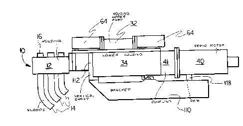
Figure 1 is a side elevation view of a gob
distributor made in accordance with the teachings of
the present invention;


f~

~2~751Z
-- 2 --

Figure 2 is a view looking downwardly into the
lower casting of the ball screw housing; and
Figure 3 is an oblique exploded view of the
coupling link and left end alignment structure of the
gob distributor illustrated in Figure 2;
Figure 4 is an enlayed illustration of another
portion of the gob distributor illustrated in Figure 2;
and
Figure 5 is an enlarged illustration of a portion
lO of the gob distributor illustrated in Figure 2.
The gob distributor includes a head 10 which has a
housiny 12 supporting a number of gob scoops 14. ~hese
scoops 14 receive and redirect gobs to a fixed array of
troughs (not shown) which feed discrete glassware
15 forming stations. The housing also supports a
corresponding number of gob receiving ends 16 which
receive gobs from a gob feeder and guide these gobs to
the scoops 14. As illustrated in figure 2, each gob
scoop 14 has a pinion 18 which interconnects with a rack
20 20 so that the gob scoops can be rotatively displaced in
unison through a desired angular range by selective
displacement of the rack.
The displacement of the rack is controlled by a
ball screw assembly 30 (figure 2) which is contained
25 within a housing having upper 32 and lower 34 parts
(figure l). ~s shown in figure 2, a ball screw 36 is
journalled into the right end wall 38 of the lower
housing 34. Rotation of the ball screw 36 by a servo
motor 40 via a coupling 41, advances or retracts a ball
30 screw nut 42. To maintain this ball screw nut 42 at its
desired orientation throughout its displacement a

lZ~7SlZ
-- 3 --
carriage 50 is secured to the ball screw nut 42 via
bolts 51. The carriage 50 extend~ towards on0 side of
the lower housing 34 and rotatably supports upper 52 and
lower (not shown) rollers which ride on flats 54 (only
the top flat is shown) defined on a support rod 56
extending between the ends of the lower housing 34. The
carriage 50 also extends toward the other side of the
lower housing 34 and suppo-rts a pair of axially spaced
cylindrical bushings 58 which slide along a second rod
59. This rod 59 extends, parallel to the first rod 56,
betw~en the ends of the lower housing 34.
A coupling 70 extends between the rack 20 and the
ball screw nut 42 and includes a forked link 72 (figure
3). An alignment device having a partial cyclindrical
15 wedge plate 74 and a securement plate 76 are secured to
the left hand (bottom) end of the forked link by
shoulder screws 78 which are received by threaded bores
79 in the wedge plate plate 74. These screws pass
freely through enlarged bores 80 in wedge plate 74 and
20 in the bottom of the link 72 thereby permitting limited
rotation of the joined plates 74, 76 about a horizontal
axis extending through the large center holes 82, 83, 84
in the securement plate 76, link 72 and wedge plate 74.
As can be seen from figure 4 the sleeve portion 85 of a
25 cylindrical wedge element 86 is inserted into the large
link bore 83 and the conical surface 87 of the wedge
portion 88 of the wedge element 86 matingly engages with
the conical surface of the wedge plate center hole 84.
The sides 89 of the wedge plate 74 are curved to
30 wedge into the curved sides 90 of a vertical channel 91
defined across the rack 20. The link will be connected

lZ9751Z
-- 4 --
to the rack by a bolt 92 which extends freely through
the larger center holes 82, 83, 84 and is received by a
threaded hole 93 in the rack channel 91.
The alignment device can rotate around the wedge
element 86 to accommodate for any departure of the rack
channel 91 from its desired vertical orientation (any
out of parallelism in the vertical plane between the
link and the rack) and the wedged sides 89 of the wedge
plate 74 will accommodate any out of parallelism in a
lO horizontal plane between the rack 20 and the link 72.
TQ permit reorientation of the top (right) ends 98
of the forked link 72 about a vertical axis each top end
98 is secured to a ball screw nut bracket 99 (figure 5)
by a bolt 100 which passes through a link aperture 101
15 and is received by a threaded aperture 102 in the
bracket 99. The bolt 100 passes through a bore 103 in a
wedge element 104 which has a sleeve portion 104
received within the link aperture 101 and a bearing
portion 105 having a cylindrical surface 106 which
20 matingly engages with a cylindrical surface 107 defined
in the bottom surface of the bracket 99. Since the
inner bore 103 of the wedge element 104 is larger than
the bolt 100, the wedge element 104 and hence the link
72 can be rotatively realigned about a vertical axis to
25 compensate for any out of parallelism in a horizontal
plane between the link 72 and the ball screw 36.
Realignment of the wedge elements 104 is also possible
about the horizontal axis coincident with the axis of
the inner bore 103.
The link 72 has a large slot 108 for clearing the
ball screw 36 throughout its range of displacement and

lZ97~i1Z

has a small slot 109 which continues the large slot 108
towards the bottom of the link 72. The link may
accordingly twist or bend to accommodate forces
generated during rack displacement due to any non-
S alignment between the rack and the ball screw.
The ball screw housing is supported by a support
bracket 110 for pivotal movement about a vertical shaft
112 and the entire gob distributor including the head
10, ball screw assembly 30 and the servo drive nut 4
lO and coupling 41 can be pivoted from an operative
position to a remote position by operating the retract
cylinder 114 which extends between a support bracket arm
116 and a lower housing arm 118.

Representative Drawing
A single figure which represents the drawing illustrating the invention.
Administrative Status

For a clearer understanding of the status of the application/patent presented on this page, the site Disclaimer , as well as the definitions for Patent , Administrative Status , Maintenance Fee  and Payment History  should be consulted.

Administrative Status

Title Date
Forecasted Issue Date 1992-03-17
(22) Filed 1987-12-17
(45) Issued 1992-03-17
Expired 2009-03-17

Abandonment History

There is no abandonment history.

Payment History

Fee Type Anniversary Year Due Date Amount Paid Paid Date
Application Fee $0.00 1987-12-17
Registration of a document - section 124 $0.00 1988-03-28
Registration of a document - section 124 $0.00 1991-07-19
Registration of a document - section 124 $0.00 1991-10-25
Registration of a document - section 124 $0.00 1991-11-06
Maintenance Fee - Patent - Old Act 2 1994-03-17 $100.00 1994-02-14
Maintenance Fee - Patent - Old Act 3 1995-03-17 $100.00 1995-02-10
Maintenance Fee - Patent - Old Act 4 1996-03-18 $100.00 1996-02-20
Maintenance Fee - Patent - Old Act 5 1997-03-17 $150.00 1997-02-26
Maintenance Fee - Patent - Old Act 6 1998-03-17 $150.00 1998-02-25
Registration of a document - section 124 $50.00 1999-01-08
Maintenance Fee - Patent - Old Act 7 1999-03-17 $150.00 1999-03-03
Maintenance Fee - Patent - Old Act 8 2000-03-17 $150.00 2000-03-02
Maintenance Fee - Patent - Old Act 9 2001-03-19 $150.00 2001-03-05
Maintenance Fee - Patent - Old Act 10 2002-03-18 $200.00 2002-03-05
Maintenance Fee - Patent - Old Act 11 2003-03-17 $200.00 2003-03-05
Maintenance Fee - Patent - Old Act 12 2004-03-17 $250.00 2004-03-04
Maintenance Fee - Patent - Old Act 13 2005-03-17 $250.00 2005-03-04
Maintenance Fee - Patent - Old Act 14 2006-03-17 $250.00 2006-03-01
Maintenance Fee - Patent - Old Act 15 2007-03-19 $450.00 2007-03-01
Maintenance Fee - Patent - Old Act 16 2008-03-17 $450.00 2008-02-29
Owners on Record

Note: Records showing the ownership history in alphabetical order.

Current Owners on Record
EMHART GLASS S.A.
Past Owners on Record
DUGA, ROBERT J.
EMHART GLASS MACHINERY INC.
EMHART GLASS MACHINERY INVESTMENTS INC.
EMHART INDUSTRIES, INC.
GLASS MACHINERY INC.
Past Owners that do not appear in the "Owners on Record" listing will appear in other documentation within the application.
Documents

To view selected files, please enter reCAPTCHA code :


To view images, click a link in the Document Description column. To download the documents, select one or more checkboxes in the first column and then click the "Download Selected in PDF format (Zip Archive)" or the "Download Selected as Single PDF" button.

List of published and non-published patent-specific documents on the CPD .

If you have any difficulty accessing content, you can call the Client Service Centre at 1-866-997-1936 or send them an e-mail at CIPO Client Service Centre.


Document
Description 
Date
(yyyy-mm-dd) 
Number of pages   Size of Image (KB) 
Representative Drawing 2001-11-23 1 10
Drawings 1993-12-07 4 100
Claims 1993-12-07 2 46
Abstract 1993-12-07 1 29
Cover Page 1993-12-07 1 11
Description 1993-12-07 6 173
Fees 1997-02-26 1 35
Fees 1996-02-20 1 40
Fees 1995-02-10 1 50
Fees 1994-02-14 1 26