Sélection de la langue

Search

Sommaire du brevet 1297512 

Énoncé de désistement de responsabilité concernant l'information provenant de tiers

Une partie des informations de ce site Web a été fournie par des sources externes. Le gouvernement du Canada n'assume aucune responsabilité concernant la précision, l'actualité ou la fiabilité des informations fournies par les sources externes. Les utilisateurs qui désirent employer cette information devraient consulter directement la source des informations. Le contenu fourni par les sources externes n'est pas assujetti aux exigences sur les langues officielles, la protection des renseignements personnels et l'accessibilité.

Disponibilité de l'Abrégé et des Revendications

L'apparition de différences dans le texte et l'image des Revendications et de l'Abrégé dépend du moment auquel le document est publié. Les textes des Revendications et de l'Abrégé sont affichés :

  • lorsque la demande peut être examinée par le public;
  • lorsque le brevet est émis (délivrance).
(12) Brevet: (11) CA 1297512
(21) Numéro de la demande: 554688
(54) Titre français: DISTRIBUTEUR DE REMBLAI
(54) Titre anglais: GOB DISTRIBUTOR
Statut: Périmé
Données bibliographiques
(52) Classification canadienne des brevets (CCB):
  • 270/184
(51) Classification internationale des brevets (CIB):
  • C03B 7/14 (2006.01)
  • C03B 7/16 (2006.01)
(72) Inventeurs :
  • DUGA, ROBERT J. (Etats-Unis d'Amérique)
(73) Titulaires :
  • EMHART GLASS S.A. (Suisse)
(71) Demandeurs :
(74) Agent: NORTON ROSE FULBRIGHT CANADA LLP/S.E.N.C.R.L., S.R.L.
(74) Co-agent:
(45) Délivré: 1992-03-17
(22) Date de dépôt: 1987-12-17
Licence disponible: S.O.
(25) Langue des documents déposés: Anglais

Traité de coopération en matière de brevets (PCT): Non

(30) Données de priorité de la demande:
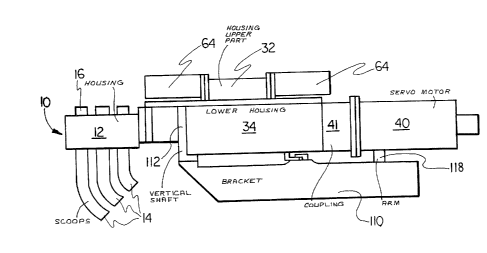
Numéro de la demande Pays / territoire Date
018,143 Etats-Unis d'Amérique 1987-02-24

Abrégés

Abrégé anglais


ABSTRACT


GOB DISTRIBUTOR


A gob distributor is disclosed having a head
including at least one gob scoop having a pinion and a
rack for interconnecting with the pinion so that the gob
scoop can be rotatively displaced through a
predetermined angular range. The rack is displaced by a
ball screw assembly wherein a vertically oriented forked
link having a bottom end and two vertically spaced top
ends connects the rack to the ball screw nut. Each of
the top ends is secured to ball screw nut so that the
link can be reoriented relative to the ball screw nut

about a vertical axis passing through the top ends to
compensate for misalignment between the ball screw and
the link and the bottom end is connected to the rack so
that any out of parallelism in either a horizontal or a
vertical plane between the link and the rack will be
accommodated.


Revendications

Note : Les revendications sont présentées dans la langue officielle dans laquelle elles ont été soumises.


The embodiments of the invention in which an
exclusive property or privilege is claimed are
defined as follows:
1. A gob distributor comprising
a head including at least one gob scoop
having a pinion and a rack for interconnecting with
said pinion so that said gob scoop can be rotatively
displaced through a predetermined angular range;
means for displacing said rack including
a ball screw,
a ball screw nut,
a vertically oriented forked link
having a bottom end and two vertically spaced top
struts,
means for securing the top end of each of
said top struts to said ball screw nut so that said
link can be reoriented relative to said ball screw

nut about a vertical axis passing through said top
ends to compensate for misalignment between said ball
screw and said link and
means for securing said bottom end to said
rack so that any out of parallelism in either a
horizontal or vertical plane between said link and
said rack will be accommodated, said struts being
selectively spaced to clear said ball screw
throughout its displacement range.


2. A gob distributor according to claim 1
where each of said top ends of the link has a
horizontally extending thru-hole therein and said
means for securing said top ends of the link each
comprises:


-6-


a wedge element having a sleeve portion for
insertion into one of said thru-holes and a wedge
portion having a bearing surface,
a bearing surface associated with said wedge
element bearing surface,
bolt means extending freely through said
wedge elements and said link thru-holes and threadingly
received by said ball screw nut.

3. A gob distributor according to claim 2,
wherein said means for securing said bottom link end to
said rack comprises:
a secured plate on one side of said link,
a wedge plate on the other side of said
link,
vertically spaced screw means extending
through link thru apertures for interconnecting said
plates,
said link thru apertures being larger than
said screw means whereby said plates can be reoriented
about a horizontal axis.

-7-

Description

Note : Les descriptions sont présentées dans la langue officielle dans laquelle elles ont été soumises.


~Z9'^~12

-- 1 --
GOB DISTRIBUTOR
SPECIFICATION
The present invention relates to mechanisms
for distributing glass gobs received from a gob
feeder -to discrete glassware forming stations.
Gob distributors include a head which
usually includes a plurality of gob scoops which can
be selectively rotated by displacing a rack which
interconnects with a pinion secured to each gob
scoop. The rack may be displaced by a servo driven
ball screw assembly. In such an arrangement there
may be some misalignment between the rack and the
ball screw and such misalignment will impose unwanted
stresses on the feed system.
It is accordingly an object of the present
invention to provide a coupling for linking the rack
to the ball screw assembly which will compensate for
any misalignment between the rack and the ball screw.
According to the above objects, from a
broad aspect, the present invention provides a gob
distributor which comprises a head including at least
one gob scoop having a pinion and a rack for
interconnecting with the pinion so that the gob scoop
can be rotatively displaced through a predetermined
angular range. Means is provided for displacing the
rack and includes a ball screw, a ball screw nut, a
vertically orien-ted forked link having a bottom end
and two vertically spaced top struts. Means is
provided for securing the top end of each of the top
struts to the ball screw nut so that the link can be
reoriented relative to the ball screw nut about a
vertical axis passing through the top ends to
compensate for misalignment between the ball screw
and the link. Means is provided for securing the
bottom end to the rack so that any out of parallelism
in either a horizontal or vertical plane between the

~297SIZ
- la -

link and the rack will be accommodated. The struts
are selectively spaced to clear the ball screw
throughout its displacement range.
Other objects and advantages of the present
invention will become apparent from the following
portion of -this specification and from the
accompanying drawings which illus-trate, in acco~dance
with the mandate of the patent statutes, a presently
preferred embodiment incorporating the principle of
the invention.
Referring to the drawings:
Figure 1 is a side elevation view of a gob
distributor made in accordance with the teachings of
the present invention;


f~

~2~751Z
-- 2 --

Figure 2 is a view looking downwardly into the
lower casting of the ball screw housing; and
Figure 3 is an oblique exploded view of the
coupling link and left end alignment structure of the
gob distributor illustrated in Figure 2;
Figure 4 is an enlayed illustration of another
portion of the gob distributor illustrated in Figure 2;
and
Figure 5 is an enlarged illustration of a portion
lO of the gob distributor illustrated in Figure 2.
The gob distributor includes a head 10 which has a
housiny 12 supporting a number of gob scoops 14. ~hese
scoops 14 receive and redirect gobs to a fixed array of
troughs (not shown) which feed discrete glassware
15 forming stations. The housing also supports a
corresponding number of gob receiving ends 16 which
receive gobs from a gob feeder and guide these gobs to
the scoops 14. As illustrated in figure 2, each gob
scoop 14 has a pinion 18 which interconnects with a rack
20 20 so that the gob scoops can be rotatively displaced in
unison through a desired angular range by selective
displacement of the rack.
The displacement of the rack is controlled by a
ball screw assembly 30 (figure 2) which is contained
25 within a housing having upper 32 and lower 34 parts
(figure l). ~s shown in figure 2, a ball screw 36 is
journalled into the right end wall 38 of the lower
housing 34. Rotation of the ball screw 36 by a servo
motor 40 via a coupling 41, advances or retracts a ball
30 screw nut 42. To maintain this ball screw nut 42 at its
desired orientation throughout its displacement a

lZ~7SlZ
-- 3 --
carriage 50 is secured to the ball screw nut 42 via
bolts 51. The carriage 50 extend~ towards on0 side of
the lower housing 34 and rotatably supports upper 52 and
lower (not shown) rollers which ride on flats 54 (only
the top flat is shown) defined on a support rod 56
extending between the ends of the lower housing 34. The
carriage 50 also extends toward the other side of the
lower housing 34 and suppo-rts a pair of axially spaced
cylindrical bushings 58 which slide along a second rod
59. This rod 59 extends, parallel to the first rod 56,
betw~en the ends of the lower housing 34.
A coupling 70 extends between the rack 20 and the
ball screw nut 42 and includes a forked link 72 (figure
3). An alignment device having a partial cyclindrical
15 wedge plate 74 and a securement plate 76 are secured to
the left hand (bottom) end of the forked link by
shoulder screws 78 which are received by threaded bores
79 in the wedge plate plate 74. These screws pass
freely through enlarged bores 80 in wedge plate 74 and
20 in the bottom of the link 72 thereby permitting limited
rotation of the joined plates 74, 76 about a horizontal
axis extending through the large center holes 82, 83, 84
in the securement plate 76, link 72 and wedge plate 74.
As can be seen from figure 4 the sleeve portion 85 of a
25 cylindrical wedge element 86 is inserted into the large
link bore 83 and the conical surface 87 of the wedge
portion 88 of the wedge element 86 matingly engages with
the conical surface of the wedge plate center hole 84.
The sides 89 of the wedge plate 74 are curved to
30 wedge into the curved sides 90 of a vertical channel 91
defined across the rack 20. The link will be connected

lZ9751Z
-- 4 --
to the rack by a bolt 92 which extends freely through
the larger center holes 82, 83, 84 and is received by a
threaded hole 93 in the rack channel 91.
The alignment device can rotate around the wedge
element 86 to accommodate for any departure of the rack
channel 91 from its desired vertical orientation (any
out of parallelism in the vertical plane between the
link and the rack) and the wedged sides 89 of the wedge
plate 74 will accommodate any out of parallelism in a
lO horizontal plane between the rack 20 and the link 72.
TQ permit reorientation of the top (right) ends 98
of the forked link 72 about a vertical axis each top end
98 is secured to a ball screw nut bracket 99 (figure 5)
by a bolt 100 which passes through a link aperture 101
15 and is received by a threaded aperture 102 in the
bracket 99. The bolt 100 passes through a bore 103 in a
wedge element 104 which has a sleeve portion 104
received within the link aperture 101 and a bearing
portion 105 having a cylindrical surface 106 which
20 matingly engages with a cylindrical surface 107 defined
in the bottom surface of the bracket 99. Since the
inner bore 103 of the wedge element 104 is larger than
the bolt 100, the wedge element 104 and hence the link
72 can be rotatively realigned about a vertical axis to
25 compensate for any out of parallelism in a horizontal
plane between the link 72 and the ball screw 36.
Realignment of the wedge elements 104 is also possible
about the horizontal axis coincident with the axis of
the inner bore 103.
The link 72 has a large slot 108 for clearing the
ball screw 36 throughout its range of displacement and

lZ97~i1Z

has a small slot 109 which continues the large slot 108
towards the bottom of the link 72. The link may
accordingly twist or bend to accommodate forces
generated during rack displacement due to any non-
S alignment between the rack and the ball screw.
The ball screw housing is supported by a support
bracket 110 for pivotal movement about a vertical shaft
112 and the entire gob distributor including the head
10, ball screw assembly 30 and the servo drive nut 4
lO and coupling 41 can be pivoted from an operative
position to a remote position by operating the retract
cylinder 114 which extends between a support bracket arm
116 and a lower housing arm 118.

Dessin représentatif
Une figure unique qui représente un dessin illustrant l'invention.
États administratifs

Pour une meilleure compréhension de l'état de la demande ou brevet qui figure sur cette page, la rubrique Mise en garde , et les descriptions de Brevet , États administratifs , Taxes périodiques et Historique des paiements devraient être consultées.

États administratifs

Titre Date
Date de délivrance prévu 1992-03-17
(22) Dépôt 1987-12-17
(45) Délivré 1992-03-17
Expiré 2009-03-17

Historique d'abandonnement

Il n'y a pas d'historique d'abandonnement

Historique des paiements

Type de taxes Anniversaire Échéance Montant payé Date payée
Le dépôt d'une demande de brevet 0,00 $ 1987-12-17
Enregistrement de documents 0,00 $ 1988-03-28
Enregistrement de documents 0,00 $ 1991-07-19
Enregistrement de documents 0,00 $ 1991-10-25
Enregistrement de documents 0,00 $ 1991-11-06
Taxe de maintien en état - brevet - ancienne loi 2 1994-03-17 100,00 $ 1994-02-14
Taxe de maintien en état - brevet - ancienne loi 3 1995-03-17 100,00 $ 1995-02-10
Taxe de maintien en état - brevet - ancienne loi 4 1996-03-18 100,00 $ 1996-02-20
Taxe de maintien en état - brevet - ancienne loi 5 1997-03-17 150,00 $ 1997-02-26
Taxe de maintien en état - brevet - ancienne loi 6 1998-03-17 150,00 $ 1998-02-25
Enregistrement de documents 50,00 $ 1999-01-08
Taxe de maintien en état - brevet - ancienne loi 7 1999-03-17 150,00 $ 1999-03-03
Taxe de maintien en état - brevet - ancienne loi 8 2000-03-17 150,00 $ 2000-03-02
Taxe de maintien en état - brevet - ancienne loi 9 2001-03-19 150,00 $ 2001-03-05
Taxe de maintien en état - brevet - ancienne loi 10 2002-03-18 200,00 $ 2002-03-05
Taxe de maintien en état - brevet - ancienne loi 11 2003-03-17 200,00 $ 2003-03-05
Taxe de maintien en état - brevet - ancienne loi 12 2004-03-17 250,00 $ 2004-03-04
Taxe de maintien en état - brevet - ancienne loi 13 2005-03-17 250,00 $ 2005-03-04
Taxe de maintien en état - brevet - ancienne loi 14 2006-03-17 250,00 $ 2006-03-01
Taxe de maintien en état - brevet - ancienne loi 15 2007-03-19 450,00 $ 2007-03-01
Taxe de maintien en état - brevet - ancienne loi 16 2008-03-17 450,00 $ 2008-02-29
Titulaires au dossier

Les titulaires actuels et antérieures au dossier sont affichés en ordre alphabétique.

Titulaires actuels au dossier
EMHART GLASS S.A.
Titulaires antérieures au dossier
DUGA, ROBERT J.
EMHART GLASS MACHINERY INC.
EMHART GLASS MACHINERY INVESTMENTS INC.
EMHART INDUSTRIES, INC.
GLASS MACHINERY INC.
Les propriétaires antérieurs qui ne figurent pas dans la liste des « Propriétaires au dossier » apparaîtront dans d'autres documents au dossier.
Documents

Pour visionner les fichiers sélectionnés, entrer le code reCAPTCHA :


Pour visualiser une image, cliquer sur un lien dans la colonne description du document. Pour télécharger l'image (les images), cliquer l'une ou plusieurs cases à cocher dans la première colonne et ensuite cliquer sur le bouton "Télécharger sélection en format PDF (archive Zip)" ou le bouton "Télécharger sélection (en un fichier PDF fusionné)".

Liste des documents de brevet publiés et non publiés sur la BDBC .

Si vous avez des difficultés à accéder au contenu, veuillez communiquer avec le Centre de services à la clientèle au 1-866-997-1936, ou envoyer un courriel au Centre de service à la clientèle de l'OPIC.


Description du
Document 
Date
(yyyy-mm-dd) 
Nombre de pages   Taille de l'image (Ko) 
Dessins représentatifs 2001-11-23 1 10
Dessins 1993-12-07 4 100
Revendications 1993-12-07 2 46
Abrégé 1993-12-07 1 29
Page couverture 1993-12-07 1 11
Description 1993-12-07 6 173
Taxes 1997-02-26 1 35
Taxes 1996-02-20 1 40
Taxes 1995-02-10 1 50
Taxes 1994-02-14 1 26