Note: Descriptions are shown in the official language in which they were submitted.
74t
CASE 4693
COAL-WATER FUEL PRODUCTION
BACKGROUND OF THE INVENTION
The present invention relates to a method and apparatus for producing
coal-water fuel (CWF) on a commercial scale which uses a unique application of
conventional, commercially available equipment.
Individual unit operations in the invention include coal crushing, rod
mi!ling, sieve bend screening, froth flotation, vacuum filtration, refuse
dewaterin~, and ball milling. These have been practiced in the coal preparation
and minerals beneficiation indus-tries for many years. The invention also uses areverse flotation operation.
The size reduction unit operations; crushing, rod millin~, and ball milling,
are common in mineral processing plants, e.~. copper and molybdenum ore
concentration operations. Rod and ball milling are not found in conventional
- coal beneficiation operations. Current practice is to avoid the production of
fine coal, primarily because of the inefficiency of conventional fine coal
cleaning operations.
In conYentional coal froth flotation, chemical rea~ents are added to the
pulverized coal-water mixture to pormit air bubbles to selectively attach to
coal particles, causing thom to rise to the surface. The particles of mineral
matter remain on the bottom of the flotation cell. For reverse flotation, a
-1-
~2~767~ -
different chemical reagent package provides for depression ~sinking) of the coalparticles and selective attachment of air bubbles to particles of liberated
pyrite. Thus, pyrite, which is the principal sulfur-containing mineral associated
with coal~ rises to the surface and can be skimmed off, resulting in a reductionof the sulfur content of the feed stream.
Froth flotation is a commercially proven technique for reducing the ash
content of the feed coal. In most conventional coal flotation applications, onlyten to twenty percent of the total plant feed is passed through the flotation
circuit. In the present invention the entire feed stream may be directed to the
flotation circuit depending on coal characteristics. Separation of the flotation
feed into coarse and fine streams (split feed) has been demonstrated to improve
the performance of the flotation circuit. Several commercial operations do
practice split feed flotation, but this is not common. Separate flotation of
coarse coal was first performed about 1960 at the pipeline plant of Hanna Coal
Company in Cadiz, Ohio. The Kerr McGee Company has also installed split
feed flotation for processing 28 mesh x 0 raw coal in their newest 1200 TPH
preparation plant. Multiple stage or "rougher-cleaner" flotation has been
practiced in the coal industry for over 20 years. The first rougher-cleaner
circuits in the coal industry in the United States were designed and installed in
196~ at three plants of E~ethlehem ~1ines Corporation in Washington County,
Pennsylvania. The rougher-cleaner flotation circuits were designed for 60 TPH
of 28 mesh x 0 coal.
The reverse flotation process has been tested at both the laboratory and
pilot plant levels (12 TPH coal feed) on a number of Pennsylvania and West
Virginia coals. These tests indicate that 70~ to 90% of the pyritic sulfur couldbe removed by reverse flotation. Much of the early work, beginnlng in the late
;
--2--
1960's, was supported by the U.S. Bureau of Mines. Technical details of the
process are available in the literature~ Several individual companies continued
this work in prlvately sponsored research programs.
The use oi a vacuum disc filter for dewatering of fine particles is common
practice in both coal beneficiation and minerals processing plants. The present
invention, however, requires more sophisticated control than commonly found in
existing coal cleaning plants. However, such sophisticated control is standard
practice in iron ore benefication systems where filter cake moisture is a crucial
pararneter in the subsequent pelletizing operation.
The final stage in the CWF production process of the present invention,
hi~h density ball milling, has been demonstrated at a pilot scale. A 50 to 100
TPD continuous pilot plant located at Kennedy Van Saun Corporation in
Danville, Pennsylvania, has been in operation since February 1982. The coal-
water fuel technology is covered in U.S. patents 4,282,006 and 4,441,887 to
Funk.
SUMMARY OF THE INVENTlON
The present invention is drawn to a method and apparatus for the
production of coal-water fuel (CWF) on a commercial scale and using a unique
combination of unit operations which, in and of themselves, are conventional.
As noted above, the individual unit operations include coal crushing, rod milling,
sieve bend screening, froth flo$ation9 vacuum filtration, refuse dewatering, andball milling, as well as a reverse flotation opèration. The opera~ions include the
production of fine particles ~hrough staged size reduction in the rod and ball
mill circuits which is not a common practice in the coal industry. Neither is
;
; -3-
, .. .. .. ..
7~7~
the complexity in scope of the froth flotation circuit found in this industry.
According to the invention the beneficiation circuit is also positioned between
the size reduction devices.
Integration of a coal beneficiation circuit in the inventive process
provides the capability of reducing the ash and sulfur content of the raw coal.
This capability expands the potential supply of acceptable raw coal feedstocks
and provides for the possiblity of supplying various quality fuels to meet
s?ecific customer requirements. The process extends the commonly accepted
limitations of conventional coal beneficiation operations. This is possible
because the fine grinding required for CWF production also results in liberationof undesirable mineral matter and pyritic sulfur from the raw coal. Production
of a coal-water fuel also eliminates the need for thermal drying of the ground
coal and the subsequent handling and storage problems associated with fine, dry
coal.
Accordin~ly an object of the present invention is to provide a me~hod and
arrangement of existing apparatus for producing a coal-water fuel comprising a
crushing and primary grinding step and equipment for liberating undesirable
components of the coal, a conventional froth flotation step ancl equipment for
pyrite rernoval, a dewatering step and equipment for concentrating the solids
content, a slurry preparation step and equipment for controlling particle size
distribution and a ref use dewatering and water clarification step and
equipment. While the indiv;dual function circuits remain constant in the
various ernbodiments of the invention, individual items of the equipment can be
substltuted. Thus in an operating plant, parallel equipment would be installed
and process piping arranged so that individual units could be by-passed ln the
event of equipment failure or for alternative product preparation.
--4--
, . ~ .
674
In accordance with one aspect of the present
invention there is provided a method of producing coal-
water fuel from raw coal, comprising crushing the raw coal
for initial size reduction of the coal; grinding the
crushed coal in a primary grinding mill; then adding water
and chemicals to the ground coal in a froth flotation
process for removing ash and coarse pyritic sulphur from
the ground coal to form a reduced-ash and reduced sulphur
coal: next adding water and chemicals to the reduced-ash
reduced-sulphur coal in a reverse flotation process for
removing fine pyritic sulphur from the coal; dewatering
the coal from the froth flotation and reverse flotation
processes; and preparing a slurry from the dewatered coal
for use as coal water fuel.
In accordance with a further aspect of the present
invention there is provided an appara~us ~or producing
coal-water fuel from raw coal comprising a crusher for
receiving the raw coal and crushing it; a primary grinder
connected to said crusher for receiving and grinding the
crushed raw coal; froth flotation means connected to said
primary grinder for receiving crushed and ground raw coal
from the primary grinder to form a reduced-ash and
reduced-pyritic sulphur coal; reverse flotation means
connected to said froth flotation means for receiving the
reduced-ash reduced-pyritic sulphur coal for further
reduction of pyritic sulphur in the coal; dewatering means
connected to said flotation means for dewatering the
reduced-ash and reduced-pyritic sulphur coal; and slurry
-4a-
.
76~74~
~orming means connected to said dewatering means for
receiving dewatered coal from the dewatering means and
forming a slurry thereof which can be used as coal-water
fuel.
~.~s -4b~
:
7~
The various features of novelty which characterize the invention are
pointed out with particularity in the claims annexed to and forming a part of
this disclosure. For a better understanding of the invention, its operating
advantages and specific objects attained by i~s uses, reference is made to the
accompanying drawings and descriptive matter in which preferred embodiments
of the invention are illustrated.
~RIEF DESCRlt'rlON OF IHE ~ .WINCS
In the drawings:
Fig. 1 is a block diagram showing an apparatus in accordance with ~he
invention for practicing the inventive method;
Fig. 2 is a schematic illustration of an alternate embodiment of the
invention;
Fig. 3 is a graph showing the particle size distribution of the flotation
feed produced by rod milling Upper Freeport coal;
Fig. 4 is a ~,raph showing the particle size distribution of the flotation
feed produced by rod milling Pittsburgh seam coal;
Fig. 5 is a ~,raph showin~ the final CWF size distribution for the Upper
Freeport seam coal test;
Fig. 6 is a graph showin~ the final C WF size distribution for the
Pittsburgh seam coal test;
~; DESCRlPTlON OF TllE PREFERRED EMBODIMENT
Referring to the drawings, the invention embodied in Fig. 1 is an appartus
and process for producing coal-water fuel.
-5-
.". ~. ~ , .
'
7~
The invention includes six functional circuits. These are the crushing and
primary grinding circuit generally designated 2, a froth flotation circuit for ash
and pyritic sulfur reduction designated 4, a product dewatering circuit
designated 6 for establishing a selected solids content9 a slurry preparation
circuit desi~nated 8 for producing a desirable particle size distribution in thefuel, and a refuse dewatering and water clarification circuit designated 10 for
treating refuse from one or more of the other functional circuits and for
clarifying water from those circuits and for reuse in the CWF production
process .
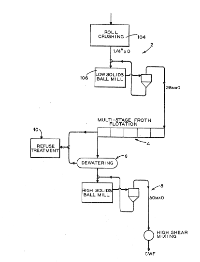
Fig. 2 shows another embodiment of the invention with a crushing circuit
22, a froth flotation circuit 24, a reverse flotation circuit 26, a dewatering
circuit 28, a slurry preparation circuit 30 and a refuse treatment circuit 32.
The separate f unctional circuits oE the invention will now be described
individually with reference to Figs. 1 and 2.
Crushin~ and PrimarY Grinding
Raw coal arriving at a plant is sampled and stored in separate piles ~not
shown) if desired. Coal would be moved from the piles to one of several raw
coal storage bins one of which is shown at 202 in Fig. 2. Separate feeders on
each bin would permit blending of coals ahead of the process to meet specific
feed requirements.
Initial size reduction of the nominal 3 to 5 inches x 0, 10-20% ash raw
coal will be accomplished using an impact type crusher 104 in Fig,. 1 or 204 in
Fig. 2. Several crushers of this type are Gommercially available. }lammermill
and cage mill designs are potentially attractive alternatives. The crushers 104
or 204 are sized and opera~ed to produce a 3/4 inch x 0 product for subsequent
.
--6--
~ ~7~
processing. An overall reduction ratio of approximately 6: l is required.
Staging of the crushers may be necessary to achieve this reduction ratio. The
maximum particle size of the crushed product may be adjusted to meet the
specific needs of the particular coal being processed.
In Fig. l the crushed coal flo~s by gravity to the primary wet grinding
operation at 106~ This wet grinding operation serves several important
functions: (l) i~ ensures a consistent coal particle size distribution to
downstream processes independent of the raw coal size distribution, (2~ it
creates highly active, freshly ground coal surface sites for subsequent froth
flotation processin~, (3) it inhibits surface oxidation of the newly produced
active coal sites, and (4) it acts as an efficient wetting/mixing/conditioning
device .
Conventional wet ball mills (206 in Fig. 2) or rod mills are potential
alternatives for this unit operation. Both of these devices are capable of
producing a 28 mesh x 0 product from the 3/4 inch x 0 feed, corresponding to a
reduction ratio of 33:1. Either mill would be operated at approximately 50%
solids. The mill operating conditions and final product size distribution will be
deterrnined by the characteristics of the coal being processed.
Two different grinding circuit designs have been considered. The first
(Fig. 2) is a conventional closed circuit wet ball milling process. In this modeof operation, the mill product is pumped to a hydrocyclone classifier 208.
Underflow from the cyclone, containing oversized coal and fine pyrite particles
(cyclone separation is based on particle mass~, is passed over a sieve bend 210.The sieve bend overproduct is returned to the mill 206 for regrinding, and the
pyrite enriched underproduct is directed to a refuse thickener 284 in circuit 32.
Cyclone overflow is directed to the froth flotation circuit 24. This type of
^7-
., , ~
~7~
circuit may be useful for coals containing a relatively high amount of coarse
pyrite contamination.
Open circuit rod milling is a second alternative (not shown). The rod mill
alternative would be expected to provide a narrower size distribution, i.e. fewer
ultrafine particles7 while still producing the minus 28 mesh product. Reducing
the amount of ultrafine particles should improve the performance of the froth
flotation circuit.
The rninus 28 mesh product from the grinding circuit 22 may be directed
to either the beneficiation circuit 24, 26 or possibly to a vacuum filtration
system 229 for dewatering in circuit 28 as feed to the slurry preparation circuit
30. The latter option will be used if the coal is of sufficient quality to meet
customer specifications without further ash or sulfur reduction. This option
may be used if a pre-cleaned coal is chosen for feed to the process.
Conven~ional Froth Flotation
.. .. . _
The performance of the flotation process is dependent to some extent on
the distribution of particle sizes present in the feed, às are all beneficiationtechniques. Flotation kinetics and optimal cell operating conditions are
particle size dependent. Therefore, close control of particle size may be
required to improve selectivity and, hence9 ash rejection and coal recovery.
The flota-tion feed may be split into coarse and fine fractions depending on thecharacteristics of the coal being processed. This choic~ involves determination
of the feed size distribution, to predict the mass flows to each circuit, and
analysis of the flotation behavior of individual size fractions. Note that the
grinding mill may be controlled to adjust the produc~ size distribution.
--8--
:~2~7~7~ ;
Referring to Fig. 2, the grinding circuit product can be classified using a
two-stage sieve bend arrangement 212. Provided the grinding mill has been
adjusted to produce a consistent minus 28 mesh product, the first stage sieve
bend is designed to separate the feed stream into 28x48 mesh at 214 (or 28x65)
and minus 48 mesh (or mlnus 65 mesh) products at 216. The actual size
diffe!entiation will be determined by the characteristics of the coal being
processed. Screening inefficiencies will result in some carry-over of fine
material with the sieve bend overproduct. This overproduct can be passed over
a second sieve bend (not shown, but a~ain designed for a 48 or 65 mesh cut) to
improve removal of the fine material. Water sprays are needed on this second
sieve bend to improve screening efficiency. The coarse and fine fractions are
collected in separate sumps for pumping to the appropriate mul~istage flotation
circuit~
Multista~e flotation involves retreating the froth product for further ash
and sulfur reduction. Typically, at least one flotation stage 218-223 would be
necessary. The actual number of stages required depends on the measured froth
product quality and charactistics of the coal being processed. Generally, each
successive stage is operated to provide an increasingly higher quality product.
Physically, the stages are located at different levels in the plant so that the
froth product frorn one stage may be gravity fed to the next. Note that no
recycling of the high ash, hi8h sulfur tailings products is intended. These
products are directed to the refuse dewatering and water clarification circuits
32 ~dash lines).
Each stage consists of one or more individual flotation cells. The froth
from each cell may be collected separately so that product quality can be
closely monitored and controlled. If necessary, the froth may be sprayed with
.
_9_
, .
~767~
water to remove any loosely held middlings particles.
Flotation reagents will be added directly to the flotation
cells or to a conditioning tank ahead of the cells. An
alcohol or glycol frother, such as methyl amyl alcohol (or
methyl isobutyl carbinol), will be used to produce a
selective, stable froth. If necessary, fuel oil (No. 2 or
No. 6) or alternative flotation promoters will be added to
improve coal recovery. The actual reagent package required
will be coal specific and must be identified by laboratory
research for each application of the process.
Separation of the grinding circuit product into
coarse and fine streams may or may not be required,
depending on the characteristics of the coal being
processed.
Following size classification of the grinding
circuit product, the solids content of the coar~e fraction
is too high for ef~ective flotation since most o~ the water
passes throu~h the sieve bend with the fine particles.
Plant recirculating water (dot-dash lines), ~rom the water
clarification operation 32, is added to the coarse coal
sump to dilute the feed to the xougher flotation unit to
approximately 10% solids. Low reagent dosages (0.1 to O.S
pounds of reagent/ton of coal) and relatively mild aeration
(0.05 to 0.20 cfm per cubic foot of cell volume) are used
in the first two rougher cells 218, to increase
selectivity. The froth products from these cells may or
may not require retreatment in the cleaner stage 219.
Additionally, chemical reagents may be added to the
remainder of the rougher cells to float as much material as
possible. These froth products may ~e directed to coarse-
cleaner floatatlon 219. The quality of the froth productfrom the last rougher cell may be substantially lower than
that from previous cells. This low grade middlings product
may be passed over a sieve bend, (not shown in the figure~
with the overproduct
10 -
returned to the crushing circuit 22 for regrinding and the underproduct directedto the refuse dewatering circuit 32.
The appropriate froths from the rougher stage 218 may be fed to the
cleaner stage 219. Water is added to the rougher cell froth launders 218 to
dilute the feed to the cleaner stage 219 to approximately 10% solids by weight.
The purpose of this stage is to produce a final clean coal product in terms of
ash and sulfur content and carbon yield. Pyrite depressing reagents, such as
CaO, KMn04, or IC2Cr207, may be added to the flotation cells to improve sulfur
reduction. The coarse cleaner froth products flow to the vacuum filter feed
sump 228. As in the rougher stage, the froth from the last cell may need to be
screened and returned to the grinding mill 206. The cleaner tailings are
directed to the refuse dewatering circuit 32.
The underflow frorn the classification of the ~rinding circuit product on
line 216 (typically 48 mesh x 0 or 65 rnesh x 0) flows directly to the fine coalrougher flotation feed sump. The feed solids content of the fine coal rougher
circuit 221 is less than that of the coarse rou~her 21S, probably on the order of
5 to 7~ solids. This lower solids content is a result of most of the water fromthe grinding circuit product (at 50% solids) passing through the sieve bend 212
witll the fine coal. It would be impractical to include a dewatering device at
this location in the process. Therefore, the fine coal rougher flotation unit 221
must handle all of this water. The dilute feed is beneficial to flotation
performance, but may increase the size or number of flotation cells required.
If necessary, the froth products from all of the f;ne rougher cells 221 may
be cleaned at 222 and then recleaned at 223 at about 10% solids by weight to
rernove ash and as much sulfur as possible. The actual number of flotation
stages will be dependent on the characteristics of ~he coal being processed.
~ 97~7~
The sulfur reduction at this point will essentially be limited to particle sizesbetween 48 and 150 mesh. The tailings from all of the stages are directed to therefuse disposal and water treatment circuit 32 for dewatering and water
clarification.
Multiple stage flotation of the fine coal produces an acceptable clean coal
product in all sizes in terms of ash content at maximum carbon recovery. Some
minus 100 mesh ?yritic sulfur may be present in the final froth product leaving
- the recleaner 223. This product can then be directed to the fine pyrite
flotation circuit 26.
Pvrite tor Reverse) Flotation
The reverse flotation circuit 26 is operated to reject fine pyritic sulfur
and maximize fine coal recovery. Reverse flotation is not applicable for ash
reduction, nor is it efficient for separation of plus 100 mesh pyrite.
Consequently, the reverse flotation circuit must be preceded by conventional
coal flotation in circuit 24.
The inventive process includes a two-stage 226, 227 re~erse flotation
circuit for reducing the sulfur content of the fine coal froth. This froth
?roductt at 20% to 25% solids by weight, must be conditioned to prepare the
particle surfaces for coal depression and pyrite flotation. Approxirnately 0.4 to
0.7 pounds of depressant reagent/ton of coal and 0.4 to 0.7 pounds of pyrite
flotation reagent/ton of coal are added to a conditioning tank 224 (dotted line).
The actual rea~ents and reagent quantities used are characteristic of the
particular coal being processed. Additionally, the tank contents must be
adjusted to a pH of 4. This acidic condition helps to remove certain chemical
groups from the pyrite particle surfaces rendering them more hydrophobic.
-12-
s~
Dilution to 15% to 20% solids may be required prior to feeding this conditioned
slurry to the rougher reverse flotation unit 226.
Previous experience has indicated that the rougher reverse flotation stage
226 produces a high sulf ur froth and a corresponding low sulf ur clean coal
tailin~s product. The reverse flotation rougher tails are directed to the clean
coal dewatering circuit 28. ~owever, the froth from the last few cells in the
rougher unit 226 may contain excessive amounts of carbon. To recover this
carbon, the rou~her froth will be retreated in a cleaner s~age 227.
The high sulfur froth product from the reverse flotation cleaner stage
227 may be passed over a sieve bend to (not shown) remove coarse coal/pyrite
particles containing a significant amount of carbon. The overproduct would
then be directed to the crushing circuit 22 for regrinding and liberation of thepyrite particles. The sieve bend underproduct would flow to the refuse dis?osal
and water treatment circuit 32 for dewatering and wa~er clarification.
The reverse flotation cleaner tails may be considered a coal middlings
product which can be returned to the reverse flotation rougher feed 226. This
product could also be sent back to the crushing circuit 22 for regrinding.
Clean Coal Dewaterin~
. .
The clean coal dewaterin~ circuit 23 must be designed to provide a closely
controlled, hi~h solids content feed to the slurry preparation circuit 30. The
approximately 25% solids feed to the disc filter 229 must be dewatered to
approximately 75% to 78% solids. This feed is comprised of the conventional
coal Ilotation froth products and the reverse flotation tailings products. Should
the beneficiatiun circuits 24 and 26 be by-passed~ ~he crushing circuit 22
product will be sent directly to the disc filter feed sump 228.
-13-
The filter feed sump 228 serves as a storage and mix tank for the filter
feed. Laboratory experience indicates that the froth from the flotation circuit
24 products should break up fairly easily under mild agitation. A consistent
filter feed at maximum solids concentration aids filter performance.
To maintain optimum filter performance, a filter vacuum must be
maintained at a constant, high level. I~ual-stage vacuum pumps are required to
maintain vacuum with ground coals of varying filter cake porosity. A second
means of maintaining a high vacuum is to ensure that the filter tub remains
full. Filter rotation speed and, hence, production of filter cake, is controlled to
match the tonnage of clean coal product from the froth flotation curcuits.
Ilowever, coal flotation products would be pumped to the filter at a rate higherthan the operating filter capacity so that a steady overflow back to the filter
feed sump 228 is provided. This overflow results in a constant flotation product
level in the filter tub of the vacuum disk filter 229. A snap blow Ieature should
be included for a good cake discharge.
The importance of the dewaterin~, circuit 28 to coal-water fuel production
cannot be overemphasized. The solids content of the dewatered product must
be kept as high as possible to provide some degree of flexibility in the
subsequent slurry production circuit 30.
Coal-~Yater Slurry Preparation
The slurry preparation circuit 30 consists of a second grinding step at 230
to produce the optimal particle size distributionO Slurry rheology is controlledin two sets of high sheer mixer tanks 23~ in series; the first for viscosity
control, the second for controlling slurry stability. .~ote that the slurry
preparation system 30, like the flotation systems 24 and 26, includes the
necessary chemical handling, storage, and metering equipment (not shown).
-- .
-14_
.~.. .
'
. ' '. .
76~
The dewatered, clean coal filter cake from the vacuum disc filter 229
falls directly onto a belt conYeyor through plastic lined chutes. Conveyor belt
scales are used to provide an accurate measurement of the feed rate to the
grinding mill 230. The cake drops into a ball mill screw feeder where a portion
of the chemical dispersant rea~ent, pH adjustment chemicals, and any required
dilution water will also be added (dotted line). The regrind ball mill 230 is
operated in a high solids mode (70% to 78/~ solids by wei~ht). Consistent
control of the product particle size distribution is achieved by controlling theviscosity of the mill coal-water slurry via the addition of chemical based
dispersants. The re~rind ball mill operatinO variables, including ball size
distribution9 ball charge loading, and mill speed, are chosen to maximize
product throughput and minimize power consumption. Since the ball mill is a
very efficient mixer, the need for sophisticated solids takedown mechanical
mixers is eliminated.
For some coals, high solids ball millin~ may not efficiently produce a
sufficient amount of very fine particles to maintain the correct rheological andstability properties of the slurry. To correct this situation, a portion of the
vacuum filter cake may be directed instead to a stirred ball rnill (not shown).
Enough water would have to be added to dilute the stirred ball mill feed to 50,S
to 60% solids. The product from this ultraEine ~rinding device would then be
added to the ball mill feed to provide the needed amount of fine particles. It is
important to note that the solids content in the ball mill 230 must be
maintained at a high level, above 70% solids. If the amount of sSirred ball millproduct is sufficient to significantly reduce the overall slurry solids content in
the ball mill, it may be necessary to return this product back to the disc filter
229 rather than feed it directly to the ball mill 230.
-15-
~ 29767~
The semi-finished coal-~ater slurry from the mill will have a viscosity
ranging from 1500 to 4000 centipoise and a solids content of 70% to 75%. This
slurry is pumped to a viscosity process blend tank (not shown) equipped with lowspeed, high efficiency impeller mixers where the remaining chemical based
dispersants are added to lower the slurry viscosity to approximately ~00 to 2000centipoise.
The product from ~he viscosity process blend tank (not shown) is pum?ed
to a high frequency vibrating screen 231 for removal of oversize material (+48
mesh particles). The amount of oversize material is projected to be less than
3% by weight and will be recycled to the ball mill 230 feed for additional
c,rindin~. This vibrating screen is an external classifier which forms a closed
grinding circuit to provide control of the maxirnum par~icle size.
The vibrating screen 231 underflow will flow by gravity to a stabilizer
process blend tank 232 for final slurry preparation. A chemical stabilizer to
inhibit particle settling and caustic chemical for p~ adjustrnent may be added
to the blend tank to obtain final product quality. All of the chemicals used in
slurry preparation are commercially available, environmentally acceptable, and
can be readily obtained fron~ existing chemical suppliers.
The final coal-water fuel (CWF) product at 240, is pumped from the
stabilizer process blend tank to storage tanks These storage tanks are
insulated and equipped with mixers to ensure product homo~eneity. The
product can be transferred from the storage tanks for shipment by tanker truck,
rail, or bar~e.
Refuse Dewaterin~and Water Clarification
The refuse dewatering and water clarification circuit 32 is designed to
prepare the plant refuse for environmentally acceptable disposal and to provide
'` ' '
7~
clean process water for reuse in the plant. Any contamination of recirculating
water can adversely affect product quality. Therefore, proper performance of
this system must be assured to maintain overall process performance and
product quality.
All of the process rejects, including tail;ngs from the conventional froth
flotation circuits 24, froth from the rougher reverse flotation operation 26, and
filtrate from the vacuum disc filter 229, flow by gravity to a static thickener
284. The thickener provides a fairly quiescent environment in which solid
particles may settle out, leaving a clarified water layer. This thickener
overflow is returned to the plant water supply system for recycling to ~he
process. Fresh makeup water must also be added to the water supply system.
Thickener underflow, at approximately 2596 to 30% solids by weight, is
pumped to a belt filter press 286 for further dewatering. The belt filter press
was selected because of its ability to handle ultra fines and clay slimes. The
belt press filtrate is returned to the static thickener 284. The dewatered refuse
Eilter cake, 60% to 80% solids by weight, is transferred to an e~ternal storage
pile by a belt conveyor for subsequent landfill disposal.
To protect the CWF production process against shutdown in the event of
an upset in any portion of the refuse dewatering and water clarification circuit,
several ponds will be constructed at the plant site. The ponds also provide
storage for excess plant water, supply process makeup water on a continuing or
ntermittent basis, and provide a receiving basin for thickener drainage during
scheduled and unscheduled plant shutdowns.
The inventive process offers several advantages for both slurry production
and coal beneficiation. These advantages may be broadly categorized as
resulting from the modular design or attributed to operating flexlbility.
-17-
7'~7~
The inven~ion evolved through consideration of distinct unit operations to
address specific functional needs such as ash and pyritic sulfur liberation, ash
reduction, pyritic sulfur removal, dewatering, and slurry preparation. This
approach resulted in a modular structure which should permit:
- Optimal management of individual unit operations.
- Sampling between modules to pinpoint sources of specific
performance problems.
- Addition of parallel units to increase plant capacity.
- Substitution of advanced unit operations as they are developed (coal
beneficiation in particular).
The invention has been designed to permit a high degree of operating
flexibility to respond to variations in feed coal quality and customer product
specifications. A few exarnples of flexibility include~
- Control of the feed size distribution to the initial milling operation
to respond to variation in the coal breakage parameters~
- Control of the size distribution to the beneficiation process
dependent on the degree of grinding required for ash and pyrite
liberation .
- Ability to by-pass the benefication circuit completely if the raw
coal quality satisfies the custorner's specifications. This would also
allow the refuse filtration system to be shut down.
- Ability to consolidate the split feed froth flotation operation.
- Ability to by-pass the sulfur reduction portion of the beneficiation
circuit for low sulfur, high ash feed coals.
The inventive CWF production process is unique in that it specifically
addresses the problem of fine particle pyritic sulfur removal.
,
~ -18-
7~
Test Results
The feasibility of the basic concept has been demonstrated in the
laboratory using several coals. The coal samples were first ground in a
laboratory batch rod mill, cleaned by multiple s~age froth flotation with a
laboratory flotation machine, dewatered by vacuum filtration, and ground in a
laboratory batch ball mill. ~epresentative test results for two coal seams, the
Upper Freeport seam coal and the Pittsburgh seam coal, are presented here.
The individual operations will be discussed sequentially.
Rod ~1illin~
The degree of prirnary grinding required for liberation of the mineral
matter and pyritic sulfur contaminants from the coal matrix is dependent on
the nature and distribution of these contaminants. The contaminants in the
Pittsburgh seam coal are more finely disseminated than those characteristic of
the Upper Freeport searn coal. Therefore, the Yittsburgh seam coal must be
ground finer to attain the desired liberation. The size distributlon of the final
coal-water fuel product represents a limlt to the amount of grinding permitted
at this stage. Flotation feed particle size distributions produced by rod milling
in the laboratory are presented in Fig. 3 and Fig. 4.
Froth Flotation
The froth flotation circuits examined included multiple stage coal
flotation and reverse flo$ation. Significant reductions in the ash and sulfur
contents of the feed were achieved with high recoveries of the combustible
material as shown in the following tableO
- 1 9-
`~ 7~7~ ~`
TABLE
FROTH FLOTATION CIRCUIT PERFORMANCE
-
PITTSBU~GH UPPER FREFPORT
PERCENT SEAM COAL SEAM COAI,
ASH IN FEED 6.08 9.17
SULFUR IN FEED 1.32 1.74
ASH IN PRODUCT 3.45 5.16
SUI~FUR IN PRODUCT 1.07 3.76
~TU RECOVERY 85 92
Vacuum Filtration
The froth products Erom the flotation testing were dewatered using a
filter leaf test kit. A range of filtration cycle characteristics and vacuum
pressures were investigated. The tests indicated that dewatered cake solids
contents ranging from 68% to 77% solids could be obtained from the fine
particle flotation products.
.
CWF Preparation
The dewatered frotll products were mixed with chemical reagents and
ground in a laboratory batch ball mill to produce stable coal water slurries. The
slurry characteristics are indicated in the following table;
::
.~
0-
:~
7~ ~
PITTSBI 1RGHUPPER FREEPORT
SEA~l COAL SEA.~I COAL
Solids Content -% 70.6 73.4
Slurry Viscosity - Cp at 870 850
100 reciprocal sec.
The particle size distributions of the slurries are presented in Figures 5
and 60
While specific embodiments oî the invention have been shown and
described in detail to illustrate the application of the principles of the
invention, it will be understood that the invention rnay be embodied otherwise
without departing from such principles.
21-
. , ~ . , , , ~ ,