Note: Descriptions are shown in the official language in which they were submitted.
2~7733
Ca se No ~ 7 9
CASEMENT WINDOW HINGE
DESCRIPTION
Technical Field
This invention pertains to a casement window
5 hinge providing for normal operation of a window sash
between a closed position and a fully-open, egress posi-
tion as well as optional movement to a washability posi-
tion. In normal operation, the window sash of a casement
window can move to a fully-open, egress position offset
10 in the window opening to enable escape through the window
in an emergency. This position does not permit easy ac-
cess to the outer side of the window sash for cleaning.
It is desirable to provide for selective movement of the
window sash to a washability position, generally centered
15 within the window opening for free access to both sides
of the sash from within the room to facilitate window
; cleaning.
Background Art
The casement window has a window sash movably
20 mounted within a frame by a pair of hinges mounted
between the window frame and the top and bottom of the
window sash. It is typical of such a hinge to have a
track mountable to the window frame and a sash arm
connectable to the window sash. A support arm inter-
25 connects the track and the sash arm, with the support armbeing pivotally connected to both the track and the sash
arm. The ~ash arm is pivotally connected either directly
or by means of an interconnecting link to a mounting shoe
which is movably guided for movement lengthwise of the
.
~297733
Case No. 79
track. Another type of casement window hinge differs
from the just-described window hinge in having the sash
arm pivotally connected to the track by an intervening
link, with the intervening link being pivotally fixed to
the track, rather than to a movable shoe, and with a sup-
port arm pivotally connected to the sash arm also being
pivotally mounted to a shoe movably guided on the track
for movement lengthwise of the track.
In both of the foregoing types of casement
window hinge, the window sash can move between closed
position and an egress position in normal operation and
when in egress position, the window sash extends
generally normal to the window frame and adjacent one
side of the window frame. This egress position maximizes
the amount of unobstructed opening to facilitate escape
through the window in the event of an emergency. In the
egress position, the inside of the window can be easily
cleaned from the room interior. However, the outside of
the window is not readily accessible. One construction
of a casement window hinge to enable movement of the
window sash from an egress position to a washability
position is shown in Taylor Patent No. 4,571,776. (U.S.)
Disclosure of the Invention
. . _ .
' A primary feature of the invention is to pro-
vide a hinge for a casement window which, by minimal mod-
ification of the prior existing structure, enables a win-
dow sash supported by a pair of the hinges to move from
an egress position to a washability position. A plural-
ity of disclosed embodiments of the invention provide for
this operation by either providing for a variation in the
length of the support arm or by shifting the pivot mount-
ing of the support arm along the track of the hinge.
~Z97733
Case No~ 79
In one embodiment of the invention, the window
hinge comprises a track mountable to a window frame and
having a movable mounting shoe which pivotally mounts one
end of a sash arm connectable to a window sash. A
support arm is pivotally connected at one end to the sash
arm intermediate the ends of the sash arm and at its
other end is pivotally connected to an anchor shoe which
is normally held in fixed position on the track. In
normal operation, the sash moves between closed and
egress position-s by movement of the mounting shoe along
the guide track and with pivotal movement of the sash arm
controlled by the support arm. When it is desired to
move the window sash to a washability position, an anchor
shoe, to which an end of the support arm is pivotally
connected, is released for movement along the track. An
anchor arm, which normally holds the anchor shoe fixed to
the track, is connected to the mounting shoe whereby both
shoes can move along the track in unison to move the sash
to washability position.
In another embodiment of the invention, the
hinge has a track mountable on a window frame and movably
mounts a mounting shoe to which an end of the 6ash arm is
pivotally connected and a support arm i6 pivotally
connected at one end to the sash arm and, at its other
end, is pivotally connected to the track. The support
arm is formed of two support arm sections in overlapped
relation and which are pivotally connected together. In
normal movement of the window sash between closed and
egress positions, the support arm sections are locked
; 30 together in an overlapped, straight-line relation. When
the window sash is to move from egress position to a
washability position, the support arm sections are freed
for pivoting movement of one relative to the other to
~Z~7733
effectively reduce the length of the support arm,
whereby the sash arm and mounting shoe can move a
further distance along the track, with resulting
movement of the window sash to washability position.
In a third embodiment, a track is mountable to
a window frame and has a movably-mounted mounting shoe
which pivotally supports one end of a sash arm
connectable to a window sash with a support arm
extending between the track and the sash arm and having
its opposite ends pivotally connected thereto. The
support arm is formed of a pair of support arm sections
which are normally in overlapped straight-line relation
and which are provided with means for holding the
support arm sections in a maximum-length position. Said
holding means is releasable to permit shortening of the
overall length of the support arm to permit further
movement of the mounting shoe along the track and
resulting movement of the window sash to washability
position.
Accordingly, the invention in one aspect seeks
to provide a hinge for a casement window providing for
normal operation of a window sash to and from an egress
position and for movement therefrom to a washability
position comprising, a track mountable on a window
frame, a mounting shoe movable along the track, a sash
arm connectable to the window sash, means pivotally
connecting one end of the sash arm to said shoe, a
support arm pivotally connected at one end in fixed
relation to the track and pivotally connected at the
other end thereof to the sash arm intermediate the ends
of the sash arm for causing movement of the mounting
shoe along the track as the window sash moves to and
from the egress position wherein the sash arm extends
generally normal to the track, and means associated with
~297733
-5-
the support arm including a releasable anchor shoe for
the support arm permits further movement of the mounting
shoe along the track to shift the sash arm and window
sash from said egress position to a washability
position. Preferably the means associated with the
support arm comprises an anchor shoe slidable in said
track to which said one end of the support arm is
pivotally connected, and releasable means for holding
said anchor shoe against movement during said normal
operations.
Still further the invention seeks to provide a
hinge for a casement window providing for normal full
opening of the window sash to an egress position and for
movement therefrom to a washability position comprising,
a track mountable on a window frame, a rnounting shoe
movable along the track, a sash arm connectable to the
window sash, means pivotally connecting one end of the
sash arm to said mounting shoe, a support arm pivotally
connected at one end to the track and pivotally
connected at the other end thereof to the sash arm
intermediate the ends of the sash arm for causing
movement of the mounting shoe along the track as the
window sash moves to an egress position with the sash
arm extending generally normal to the track, and means
for reducing the efEective length of the support arm
when the window sash is in said egress position to
permit further movement of the mounting shoe along the
track to shift the sash arm and window sash from said
e~ress position to a washability position.
~Z97733
Case No. 79
Brief Descrlption of the_Drawin~s
Fig. 1 is a plan view of a first embodiment of
the hinge, showing the components in egress position;
Fig. 2 is a plan view of the hinge, with the
components in window-closed position;
Fig. 3 is an elevational view of the structure
shown in Fig. 2;
Fig. 4 is a plan view of the structure of Fig.
1 shown in window-washability position;
10Fig. 5 is a sectional view, on an enlarged
scale taken generally along the line 5-5 in Fig. 2;
Fig. 6 is a sectional view, on an enlarged
scale taken generally along the line 6-6 in Fig. 2;
Fig. 7 is a sectional view, on an enlarged
scale taken generally along the line 7-7 in Fig. 2;
Fig. 8 is a plan view of a second embodiment of
the hinge with the components shown in egress position;
Fig. 9 is a plan view of the hinge shown in
Fig. 8, with the components in closed position;
20Fig. 10 is an elevational view of the structure
shown in Fig. 9:
Fig. 11 is a plan view of the structure shown
in Fig. 8, positioned in window-washability position;
Fig. 12 is a sectional view, on an enlarged
25scale taken generally along the line 12-12 in Fig. 9;
Fig. 13 is a sectional view, on an enlarged
scale taken generally along the line 13-13 in Fig. 9;
Fig. 14 is a plan view of a third embodiment of
the hinge, with the components shown in egress position;
30Fig. 15 is a plan view of the hinge shown in
Fig. 14 with the components in closed position;
Fig. 16 is an elevational view of the structure
shown in Fig. 15;
~297733 case No. 79
Fig. 17 is a plan view of the structure shown
in Fig. 14 in washability position for the window; and
Fig. 18 is a sectional view, on an enlarged
scale taken generally along the line 18-18 in Fig. 15.
Best Modes for Carryin~ Out the Invention
The first embodiment of the invention is shown
in Figs. 1 to 7.
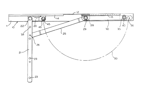
~ n elongate track, indicated generally at 10,
is mountable to a window frame and has a horizontally
disposed planar portion 11 with an upstanding side wall
12, with a pair of spaced-apart, inwardly-turned flanges
14 and 15 overlying the horizontal section 11 of the
track and which have down-turned ends to form guide
channels for coacting shoe structures.
A mounting shoe 20, which is typically formed
of a molded plastic, has an upturned flange slidably
fitted within the guide channels associated with the
flanges 14 and 15 and slides on the elongate track 10.
The mounting shoe 20 pivotally mounts a sash arm 21 at a
pivot connection 22, with the sash arm being attachable
to the bottom of the window sash by fastening members
(not shown) extended through openings 23. A comparably
constructed hinge would be mounted to the top of the
window sash to provide both top and bottom support for
the window sash.
A support arm 25 is pivotally connected at one
of its ends to the sash arm 21 at a distance from the
pivotal mounting thereof to the mounting shoe 20 by means
of a pivot connection 26. The other end of the support
arm 25 is pivGtally connected to an anchor shoe 28 by a
rivet 29. With the anchor shoe 28 releasably held in the
position shown in Fig. 1, the sash arm 21 can move
~lZ97~33
Case No. 79
--8--
between the closed position, shown in Figs. 2 and 3, and
the fully-open, egress positiGn, shown in Fig. 1, by
movement of the mounting shoe 20 along the track 10 and
pivoting of the support arm 25 at the pivot connections
26 and 29 at the opposite ends thereof. In the egress
position of Fig. 1, the window sash is positioned
adjacent one side of the window frame, to maximize the
window opening to facilitate escape through the window if
re~uired in an emergency.
The window hinge is shown positioned in a
washability position in Fig. 4 wherein the sash arm 21
has moved to a position more nearly the middle of the
length of the track 10. This moves the window sash to a
position more nearly the center of the window opening
whereby easy access may be had to both sides of the
window sash for cleaning thereof.
The movement from the egress position of Fig. 1
to the washability position of Fig. 4 is achieved by
further movement of the mounting shoe 20 along the track
10, which is permitted by releasing the anchor shoe 28
from its fixed relation with the track 10. The anchor
shoe 28 i8 normally held in fixed relation by an anchor
arm 30 which, at one end, is pivotally-mounted on the
rivet 29 carried by the anchor shoe, as seen in Fig. 6,
and'is spaced from the support arm 25 by a washer 31.
The anchor arm 30 is provided with a pair of oppositely-
facin~ notches 35 and 36 adjacent an end thereof. The
notch 35 coacts with a lock member in the form of a snap
collar 38 surrounding a rivet 40 fixed to a raised part
41 of the track 10 as seen in Fig. 7 and this holds the
anchor arm 30 to maintain the anchor shoe 28 in fixed
position on the track.
~297733 Case No. 79
As seen in Fig. 5, the mounting shoe 20 has a
retention member comprising an insert 44 which fixedly
mounts a rivet 45 which is surrounded by a snap collar
46. The anchor arm 30 can be manually released from the
snap collar 38 by a force exerted in a clockwise
direction, as viewed in Fig. 1, and the anchor arm
pivoted through an arc, as indicated by the broken line
50 in Fig. 1 to a position wherein the notch 36 engages
with the snap collar 46 to lock the anchor arm to the
mounting shoe. This frees the anchor shoe 28 for
movement along the track 10 and interlocks the anchor
shoe with the mounting shoe 20 whereby the sash arm 21
can move to a washability position, as seen in Fig. 4.
An end S0 of the raised part 41 of the track lO forms a
stop for enga~ement with the anchor shoe 28, as seen in
Fig. 4, to limit the movement of the parts to a
washability position.
After washing of the window, the mounting shoe
20 and anchor shoe 28 can be returned to the positions
shown in Fig. 1 and the anchor arm 30 released from the
snap collar 46 and returned into engagement with the snap
collar 38. ThLs restore~ the support arm 25 to a fixed
pivoting positLon relative to the track 10 and there can
then be normal operation of a window between closed and
egréss positions.
A second embodiment of the invention is shown
in Figs. 8 to 13 wherein a track, indicated generally at
60, iB mountable on a window frame and is of generally
the same construction as the left-hand part of the track
shown in Fig. 1 with a horizontal planar section 61, a
side wall 62 and a top flange 63 with a downwardly-
depending channel for movably guiding a mounting shoe 65.
The mounting shoe 65 can move along the track 60 and
~Z97733
Case No . 7 9
--10--
pivotally mounts a sash arm 70 at one end by a pivot
connection 71. The sash arm 70 has a series of openings
72 for receiving fasteners (not shown) for attachment to
the underside of a window sash whereby the sash arm and
window sash can move between a closed position and the
egress position shown in Fig. 8~
A support arm indicated generally at 75, is
pivotally connected at one end to the sash arm at a
distance from the mounting shoe 65 by a pivot connection
76 and at its other end is pivotally connected to the
track by a pivot connection 77. In normal movements of
the window, the components of the hinge can move from the
closed position, shown in Figs. 9 and 10, to the egress
position, shown in Fig. 8. In order to move the window
sash from egress position to a washability position shown
in Fig. ll, the support arm 75 is constructed for
adjustment of the effective length thereof.
- More specifically, the support arm is formed of
two support arm sections. A first support arm section 80
is pivotally connected to the sash arm 70 by the pivot
connection 76, previously referred to, and a second arm
cection 81 is pivotally connected to the track by the
pivot connection 77, previously referred to. The two
,support arm sections 80 and 81 are pivotally connected
togéther by means of a rivet 84, as seen particularly in
Fig. 13, and with a washer 85 positioned therebetween.
In normal operation, the support arm sections 80 and 81
are in straight-line, overlapped relation, as seen in
Fig. 8. When the window sash is to be moved from the
egress position of Fig. 8 to the washability position of
Fig. 11, the support arm sections are caused to pivot
relative to each other about the rivet 84 to bring the
~Z977~3
Case No. 79
first support arm section 80 into general alignment with
the sash arm 70 which reduces the effective length of the
support arm whereby the mounting shoe 65 can more further
to the right along the track 60.
The support arm sections S0 and 81 are normally
held in aligned relation by releasable holding means in
the form of a protruding slug 90 ~itted within an opening
91 in the support arm section 81 and extending upwardly
above the upper surface thereof, as shown in Fig. 12, for
engagement within an opening 92 in the support arm
section 80. The support arm section 80 has a tab 95
whereby the support arm section 80 can be pulled upwardly
to free it from engagement with the protruding slug 90
and permit the movement of the support arm section 80
through an arc as shown by the broken line 96 in Fig. 11
to a position wherein the tab 95 will engage with the
lower rail of the window sash and limit the pivotal
movement thereof.
The movement of the support arm section 80 to
the position shown in Fig. 11 shortens the effective
length of the support arm to be the length of the support
arm section 81 which enables the mounting shoe 65 to
carry the sash arm to the washability position.
When the window is to be returned to the egress
pos;tion from the washability position, the sash arm 70
i8 moved to the left, as viewed in Fig. 11, to the
position shown in Fig. 8, which brings the support arm
sections back into alignment and support arm section 80
can be reengaged with the protruding lug 90.
Alternatively to grasping the tab 95 to raise the support
arm section 80, the support arm section 80 can be pried
upwardly for separation from the protruding lug 90.
~Z~7733
Case No. 79
-12-
A third embodiment of the invention is shown in
Figs. 14-18. A track, indicated generally at 100, has a
horizontal planar length 101 with a side wall 102 and an
overhanging flange 103 providing a guide channel for a
mounting shoe 105. A sash arm 110 is pivotally mounted
to the mounting shoe at 111 and has a series of openings
112 for fastening means Inot shown) to secure the sash
arm to the underside of a window sash. A support arm,
indicated generally at 120, is pivotally connected at one
of its ends to the sash arm at a distance from the
mounting shoe 105 by the pivot connection 121 and the
othex end of the support arm is pivotally connected to
the track 100 by a pivot connection 122.
The support arm 120 is formed of two support
arm sections to enable varying the effective length
; thereof. A first support arm section 125 is pivotally
connected to the sash arm 110 at the pivot connection
121, while a second support arm section 126 is pivotally
connected to the track 100 by the pivot connection 122.
The support arm sections are slidably interconnected by a
! pair of pin and slot connections. The Pirst 8upport arm
section 125 has a slot 130 coactinq with a pin 131
extending upwardly from the second support arm section
126. The second support arm section 126 has an elongate
25 slo't 135 coacting with a pin 136 depending downwardly
from the first support arm section 125. Each of these
pins is defined by a rivet, as seen particularly in Fig.
18, which has heads to hold the support arm sections
together. A pair of washers 140 and 141 is positioned
between the overlapping parts of the support arm sections
and surrounding the rivets 131 and 136 to facilitate
sliding movement of the support sections relative to each
; other~
~29773;~
Case No. 79
-13-
The support arm sections 125 and 126 are held
in a full effective length position, as shown in Fig. 14,
by means of a removable screw 145 fitted within a
- countersink in the first support arm section 125 and
threaded at 146 into a threaded open~ing in the second
support arm section 126. When the window sash is to be
moved from an egress position, with the hardware
positioned as shown in Fig. 14, to the washability
position of Fig. 17, the screw 145 is removed which
permits a lengthwise contraction of the support arm
sections to enable movement of the mounting shoe 105 to
the right to the position shown in Fig. 17. When the
window is to be moved back to a position for normal
operation, the sash arm llO is moved to the left from the
position of Fig. 17 to the position of Fig. 14, which
brings the support arm sections into position for
reinsertion of the screw 145 to secure the support arm at
its maximum effective length, whereby the window can move
between closed and egress positions.
The term "casement window" is used throughout
the specification and claims in its broadest sense to
mean a window having a sash movable on hinges regardless
of whether pivoting i8 about a horizontal or vertical
axis.