Note: Descriptions are shown in the official language in which they were submitted.
~29~0
M-510
METHOD OF FABRICATING A
~OWER T~ANSMISSION BELT AND APPARATUS THEREFOR
Technical Field
~his invention relates to a method of fabricating a
power transmission belt and an apparatus for carrying out
the method. Particularly, the invention relates to such a
belt manufacture wherein individual vulcanized belt preforms
are machined to have any one of a plurality o~ different
cross-sectional shapes. In the illustrated embodiment, the
belt is brought to its desired cross section by cutting the
sidQ edges.
Backaround Art
It iB conventional to form a plurality o~ power
transmitting belts from a vulcanized ~leeve. Such sleeves
arQ conventionally formed by wrapping succes~ive layers of
the belt components about a mandrel. Upon completion of the
w lcanization of the sleeve, the sleeve is cut lengthwise to
define a plurality of separate belt preforms.
It is conventional to cut the belt elements to the
desired trapezoidal shape 80 as to define individual V-belts
without further machining operations. A problem has arisen,
however, in connection with such belt manufacture, in that
the V-belts often vary from one to the other in length and
cros3-sectional shape due to machining errors such as may
result, for example, from the thermally shrinking material
characteristics of the belt. Further, the tensile elements
of the belt are often displaced causing shortened useful
life of the belt in power transmission use.
Alternatively, the sleeve may be cut to the desired
shape before w lcanization and the individual belts
w lcanized in a suitable mold. Such manufacture similarly
does not provide completely satisfactory belt structures.
12~ o
M-510
It ia common to form the ~ide surface~ of the belt by
gr~nding. Such gr~nding of the belt material, however, may
not only affect the length of the belt but vary the position
of the belt relative to the axial center of the pulleys with
the belt entrained thereabout.
AB a result of the inaccuracies in such manufacture,
conventional power tran6mission belts are often sub~ect to
vibration and variation in belt tension during use not only
causing shortening of the useful life of the belt but
producing undesirable vibrations in the machine being
driven.
Because of the variations in the belt dimension, it has
been common to ~easure the respective belts to 6elect those
having the proper dimensional characteristics and ~ub~ecting
those that do not havs the desired characteristlcs to
further ~orming steps such as grinding of the 6ide surfaces
of the belt 50 as to permit the bel~ to seat more deeply in
the pulley and thereby shorten the effective length of the
belt.
It i8 known to effect the separation of the vulcanized
sleeve into individual V-belts by the use of a rotating
grinder rather than cutting tools. Further, the V-shaped
portion of the belt may be formed by an abrasive plate while
rotating the sleeve on a mandrel with the individual V-belts
then being separated from each other by a suitable cutter.
The use of grinding or abrasive means in form~ng the
V-shaped belt has the disadvantage of causing the surface
temperature of the rubber ~o be relatively high such as 100
C. or higher a~ a result of the frictional heat developed in
the grinding operation. Such high temperature causes the
molecular bonds o~ the surface rubber to be broken and
thereby causes the 6urface rubber to be devulcanized. The
pressure and frlctional forces required in such grinding
~2981~ 0
M-510
operations may dlstort ths rubber so that the grinding
operations may not result in an accurately preselected
V-shaped con~iguration of the belt.
A further problem arises in such grinding of the belt
in that variations in th~ hardness of the rubber require
diffQrent abrasive characteristics and thus the grinding
mean~ is not always accurately coordinated with the
requirements of the ~ater~al being ground, resulting in
defective belt manufacture.
The forming of the V-belts by such grinding manu~acture
has the further disadvantage of necessitating the use of a
substantial number o~ manu~acturing steps and handling
operations incrQasing the costs and manufacturing t~me.
Disclosur~ o~ the Inventlon
The present lnvention comprehends an improved method
and apparatus o~ power transmi~sion belt manufacture which
overcomes the disadvantages o~ the prior art manu~actures
and which provides improved accuracy ln the desired length
and cross-sectional shape of the V-belts.
The present invention produces a high ratio of
acceptable belt~ at minimum cost and permits improved speed
and ~acility o~ manufa~ture. Spot chec~ing of belt~ for
accuracy o~ cross-sectional con~iguration is sufficient as
opposed to the requirement o~ checking each belt in the
conventional manu~acturing process.
The invention in one broad aspect comprehends a method
of forming power transmission V-belts comprising the steps of
providing a belt sleeve, dividing the belt sleeve into a
plurality of belt preforms defining opposite side portions
and a back surface, situating individual belt preforms around
a pair of spaced pulleys, driving the belt preforms on the
spaced pulleys and seriatim forming V-belts from the preforms
by simultaneously cutting the side portions of the individual
belt preforms as the belt preforms are being driven about the
pulleys to define opposite converging side surfaces of the V-
belt by moving first and second -cutter blades towards each
~Z9~70
3A
other so that the first and second cutter blades tend to wedge
the belt preforms situated around the pulleys away from the
pul:Leys. The wedging movement of the belt preforms is limited
by the first and second cutter blades so that the first and
second cutter blades consistently cut the side portions of the
belt preforms.
Further still the invention comprehends apparatus for
forming power transmission V-belts comprising means for
dividing a belt sleeve into a plurality of belt preforms each
having opposite side portions and a back surface and a pair of
spaced pulleys around which individual belt preforms can be
placed. There is means for driving the belt preform about the
spaced pulleys, and means for seriatim forming V-belts from the
preforms by simultaneously cutting the side portions of the
individual preforms as the preform is being driven about the
spaced pulleys to define opposite converging side surfaces of
the V-belt. The forming means includes first and second
cutters and means for translating the cutters in substantially
colinear paths towards each other and against the belt preform
being cut.
The invention also comprehends apparatus and method
for forming power transmission V-belts, wherein there is means
for dividing a belt sleeve into a plurality of belt preforms
each having opposite side portions and a back surface, and a
pair of spaced pulleys around which individual belt preforms
can be placed. Means is provided for driving the belt preform
about the spaced pulleys, and means is provided for seriatim
forming V-belts from the preforms by simultaneously cutting the
side portions of the individual preforms as the preform is
being driven about the spaced pulleys to define opposite
converging cut side surfaces of the V-belt. Means smooth the
cut side surfaces of the belts.
More particularly the invention discloses belt
manufacture wherein a preformed sleeve is separated into a
plurality of individual belt preforms having illustratively
a square or rectangular cross section. The preforms
are individually subjected to a belt forming operation
wherein the side wall surfaces of the
individual belts are cut by rotating cutting
-_"
~ . .
12~
M-SlO
bladee while the belt is entrained about a pair of pulleys
80 as to be driven under tension.
Guide rolls are associated with the cutting tools to
ma$ntain accurate lateral disposition of the preform as it
is being cut.
A suitable roller i8 engaged with the bac~ surface of
the belt to provide and maintain stability in the feeding of
the belt about the pulleys during the cutting operation.
The individual belt preforms may be entrained about the
pulleys either manually or by automatic belt feeding means.
The pulleys are automatically selectively positioned to
receive the preforms and then to effect power transmitting
of the belt during the cutting operation.
The cutting means comprisee in the illuetrated
embodiment a pair of belt machining units each having at
least one rotatable cutting blade for cutting the side wall
of the belt. An X-axie movable base is provided for
carrying the belt machining units so ae to align the cutting
blades ae desired with the belt side edgee by movement
transversely to the exposed outer surface of the entrained
belt.
A Y-axis movable base i8 provided for eupporting the
roller engaging the back surface of the belt by movement in
a direction perpendicular to the X-axis movable base.
The driven pulley ie ad~ustably posit~onable so as to
provide a desired tension in the driven belt. The cutting
tools are caused to engage the tensioned portion of the belt
running from the driven pulley to the drive pulley.
The cutting tools are engaged with the eide edges of
the belt preform after the belt ie accurately centered by
the guide rolla to assure accurate forming of the side
surfaces of the belt.
~2~
M-510
The back surface rollers are aligned with the cutting
tool units BO a8 to accurately position and reinforce the
unsupported portion o~ the belt being cut between the drive
and driven rollers during the cutting operation.
5Upon completion of the forming of the V-belt by the
cutting units, the cutting units are moved away from the
side surfaces of the belt on the Y- and X-axis movable bases
while at the same time the roller is disengaged from the
back surface of the belt. Tension on the belt i~ relieved
by moving the driven pulley toward the drive pulley and the
belt is then removed from entrained relationship with the
pulleys. Such removal may be effected automatically or
manually, as desired.
Thus the improved power transmission belt manufacture
of the present invention is extremely simple and economical
whil~ yet providing a highly improved accurate belt
manu~acture as discussed above.
B~ie~ De~cription of the Drawinas
Fig. 1 is a fragmentary, transverse section of a belt
sleeve illustrating in broken lines the separation thereof
into a plurality of individual belt preforms for further
processing in the manufacture of desired V-belts;
Fig. 2 i8 a front elevation of an apparatus for
fabricating a power transmission V-belt embodying the
invention;
F~g. 3 i~ a side elevation thexeof with portions
removed to facilitate illustration of the structure thereof;
Fig. 4 i5 a fragmentaxy, top plan view of the
apparatus;
30Fig. 5 i5 a fragmentary, sectional view taken
substantially along the line 5-5 of Fig. 4 with belt
machining units in Fig. 4 removed;
12~ Q
M-510
Flg. 6 is a transverse sectional view taken
substantially along the line 6-6 of Fig. 4 wlth the belt
machining units removed;
Fig. 7 is a fragmentary, side elevation of a cutting
blade adapted for use in the belt manufacture embodying the
invention:
Fig. 8 is a fragmentary, side elevation of part of an
automatic belt transfer structure along the line 8-8 of Fig.
2;
Fig. 9 is a fragmentary, side elevation illustrating an
automatic belt mounting unit associated with the apparatus;
and
Fig. 10 is a schematic view illustrating the
cooperating belt guiding and cutting structure for providing
the improved belt manufacture.
Description of the Preferred Embodiment
Fig. 1 depicts in cross section a portion of a
conventionally formed, layered belt sleeve at 10 from which
individual belts can be formed according to the invention.
The arrangement of layers exemplifies one known belt
con3truction, however this particular arrangement i8 not
requisite to the performance of the inventive method of
forming belts.
The division of the sleeve 10 into a plurality of
square or rectangular belt preforms 12 i8 indicated by
dotted lines 14 in Fig. 1. Each belt preform 12 has an
inner, exposed, bias canvas layer 16 and an overlying bias
canvas layer 18. The canvas layers 16, 18 are stretchable
and have generally the same 90-155 relationship of crossing
warp and weft yarn~. The outer portion of each belt preform
12 has an exposed canvas layer 20 and an underlying canvas
lZ~ 7~)
M-5}0
layer 22, which layers 20, 22 are similar to the
aforementioned canvas layers 16, 18.
~ he midportion 24 of each preform 12 i~ made from
rubber and has an outer tension section 26 and an inner
compression ~ection 28 that i~ thicker than the tens~on
section 26. High ~trength tens~le cord~ 30 res~de between
the sections 28, 30 and are pre*erably defined by spirally
wound polyester *ibers with a high resistance to elongation.
Short *ibers made from, *or example, cotton or nylon, may be
arranged randomly in generally transverse orientation to the
belt length in the compression section 28 of the belt.
The sleeve in Fig. 1 is vulcanized by conventional
pressure heating means and procedure~. After vulcanization
a cutter (not shown) seYers the sleeve 10 along the lines 14
to separate the individual preforms 12. The con*iguration
of the preforms i~ not limited to the lllustrated
rectangular con~iguration or the a~orementioned 6quare
configuration and may, for example, have a parallelogram-
shape in cross section. The belt preforms 12 are in any
event rough cut and the present invention is directed to the
precise machining of the laterally oppositely facing side
edges 32, 34 of each belt pre~orm 12 to a desired
configuration. Machining o* the belt side edges 32, 34 is
carried out through the inventive apparatus shown generally
at 36 in each of Fig~. 2-4.
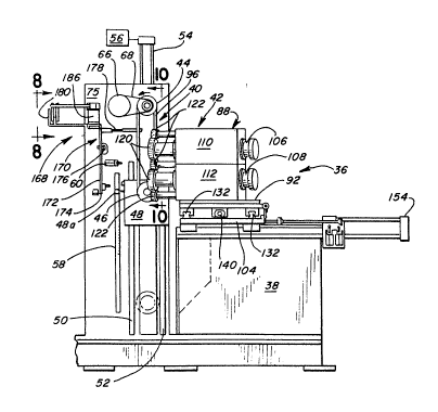
The machining apparatus 36 comprises generally a frame
38 with a belt mounting station at 40 and a two-axi~ grinder
mechanism at 42. At the belt mounting ~tation 40, two
vertically spaced pulleys 44, 46 are mounted to the frame 38
*or rotation about parallel axes. The upper pulley 44 is a
drive pulley and is in vertically fixed relationship to the
frame 38. The lower pulley 46 is a driven pulley and is
carried on a slider 48 which i~ guided in a vertical path
12S~
M-510
selectively toward~ and away from the drive pulley 44 by
spaced, upright rails 50, 52 on the frame 38. Controlled
vertical positioning of the slider 48 iB accomplished
through a cylinder 54 which i6 operated through a
conventional type control 56. A graduated scale 58 is fixed
on the frame 38 and gives a visual indication of the
position of the slider 48 relative to the frame 38 and
thereby gives an indication of the spacing between the
centers of pulleys 44, 46 and the precise length of a belt
12 entrained thereon. The upper limit of the range of
movement of the slider 48 i5 determined by a limit switch
60, which contacts an arm 48a, which follows vertical
movement of the slider 48. At the upper limit of travel for
th2 slider 48, the arm 48a engages the switch 60 and arrests
opoeration of the cylinder 54. ~he spacing of the pulleys
44, 46 can be ascertained from the po~ition of the arm 48a
along the scale 58. A predetermined tension on a belt 12
entrained on the pulley6 44, 46 is thus established by
selecting a predetermined vertical position of the slider 48
automatically through control 56.
The pulley 44 i8 driven by a motor 62 which has a drive
shaft 64 carrying a pulley 66. A drive belt 68 transmits
motion from the pulley 66 to the pulley 44. The drive
pulley 44 has axislly spaced sheave portions 70, 72. A coil
spring 74 biase~ sheave portion 70 axially outwardly from an
upright ~ection 75 on the frame 38 and coil spring 76 biases
sheave portion 72 axially oppositely BO that the pulley 44
is maintained in a predetermined position on its mounting
shaft 78 by the opposing spring force~ and the sheave
portions 70, 72 are biased against the side edges 32, 34 of
the belt preform 12. Coil springs 80, 82 serve the same
function as springa 74, 76 and act on corresponding sheave
portiona 84, 86 on the driven pulley 46. It should be
M-510
understood that the described pulley construction is not
limiting and one alternative thereto iB to utilize flat
pulley~ with fixed flanges.
The grinder mechanism 42 consists of spaced machining
unit~ 88, 90 which 6eparately and concurrently act on
opposite edges 32, 34 o~ the belt preforms 12. The units
88, 90 are carried on separate bases 92, 94 respectively,
which bases 92, 94 are mounted for X- and Y-axis movement
relative to the frame 38, a~ hereinafter described, and
along the X-axis for movement substantially at right angles
to the vertical, t2nsioned portion 96 of a belt 12 entrained
on the pulleys 44, 46.
Movement of the units 88, 90 towards the left in Figs.
2 and 4 brings rollers 98 (Fig. 6) on a pu~h roll assembly
100 between the units 88, 90 against the outer sur~ace 102
of a belt 12 on the pulleys 44, 46 to reinforce the
tensioned portion 96 of the belt that is otherwise
unsupported between pulleys 44, 46 and 80 that the tensioned
portion 96 of the belt 12 i~ consistently positioned in
relationship to the grinder mechanism 42. Base 104 carries
the grinder mechanism 42 and translates the mechanism 42 as
a unit along the X-axis relative to the frame 38.
The mechanical detatls of the grinding mechanism 42 are
shown in Figs. 2-4 and 7 and the mechanism 42 i5 shown
schematically in Fig. 10. The construction of each of the
units 88, 90 is substantially the same with slightly
different orientation of part and thus detailed discussion
will be limited herein to one exemplary unit 88. The unit
88 has vertically spaced ~hafts 106, 108 ~ournalled for
rotation about parallel axes within housings 110, 112
respectively carried on the base 92. The axes of the shafts
106, 108 are parallel to each other and the intended plane
o~ the finished ~ide edge 34 of the belt 12. The shafts
8~
M-510
106, loa are driven respectively by motors 114, 116 through
associated belts 118 (one ~hown in Fig. 4).
The 6hafts 106, 108 each carry at their free end a
cutting blade 120, which is shown in detail in Fig. 7. The
cutting blades 120 preferably have anywhere from 10 to 100
teeth 121, with + 40 of twisting angle rake angle (~) from
0-60 and relief angle (~) of from 0-30. The width of the
blade 120 is greater than the width of the belt~ edges 32,
34 80 that complete cutting of the belt edges 32, 34 occurs.
10 AB an alternative to the use of a blade such as that shown
in Fig. 7, an abrasive can be u6ed.
As most clearly seen in Figs~ 3 and 10, the blades 120
on 6hafts 106 and 108 are in vertical alignment. The blade
120 on ~haft 106 rotates in a counterclockwise direction in
Fig. 10 and the blade 120 on ~ha~t 108 rotates oppositely
thereto, i. Q. counterclockwise. Counterclockwise rotation
of drive pulley 44 in Fig. 2 causes the tensioned portion 96
of the belt 12 to travel upwardly. ~g the belt 12 i~ being
driven, the cutter 120 on ~ha~t 108, which cutter 120
rotate~ in the same direction as belt travel, fir~t machines
the belt edge 34 to the desired angle, a~ determined by the
orientation of the unit 88 and the associated axes of shafts
106, 108. The oppositely rotating blade 120 on shaft 106
then removes any remaining burrs to produce a finished,
6mooth surface on the edge 34.
To assure consistent vertical travel of the belt
portion 96 between cutter blades 120 and spaced machining
unit~ 88, 90, a plurality of guide rollers 122 are provided
on machining unit 88 and a corresponding plurality o~ guide
rollers 124 are provided on unit 90. The peripheral
sur~aceR of roller~ 122, 124 define a vertical belt path and
closely guide the oppositely ~acing edges 32, 34 of the belt
12. The guide rollers 122, 124, while ~hown fixedly
M-5 10
11
attached to the machining unit~ 88, 90, may alternatively be
carried directly by the bases 92, 94, respectively. With
the rollers mounted 122, 124 on the bases 92, 94, the
roller~ 122, 124 might be oriented in perpendicular
relationship to their position shown in the figures and
accomplish the samQ end.
It i8 not necessary to have intimate contact between
the guide rollers 122, 124 and belt sides 32, 34 during a
cutting operation. It is sufficient if an interval is
10maintained between the guide rollers 122, 124 and belt sides
32, 34, on the order of two millimeters or less. This
allows clearance to accommodate regularities in the belt
cro~s section and at the sam~ time the rollers 122, 124
smoothly and consistently guide travel of the belt.
15Con~istent positioning o~ the unit~ 88, 90 relative to
the frame 38 and thus the belt 12 entrained on the pulleys
44, 46, is insured by the provision of aligning stops 126,
128 associated with bases 92, 94. Consistent positioning of
the units 88, 90 relative to the belt 12 is further assured
by the push roll assembly 100, which bears on the outer
surface 102 side of the belt 12. In the absence of the push
roll assembly 100, there is a tendency of the units 88, 90
which, in operation, simultaneously act on the opposite
sides 32, 34 of the belt 12, to urge the belt 12 toward the
right in Fig. 4 becau~e of the relative angular orientation
of the belt side~ 32, 34.
The bases 92, 94 are mounted for guided translatory
movement along rails 132 simultaneously towards and away
~ from the side edges 32, 34 of belt 12 entrained on the
30pulleys 44, 46. The bases 92, 94 are interconnected by a
central shaft 134 having oppositely threaded lengths 136,
138 associated with the bases 92, 94 reæpectively. The
shaft 134 is connected to the bases 92, 94 through ball
M-510
~oint~ 140 and operated by ~ pulse motor 142 connected at
one end of the ahaft 134. Limit ~witches 144 are provided
on the~ frame 38 and cooperate with an arm 146 on the base 92
to limit the range of travel of the bases 92, 94.
The aforementioned push roll assembly 100 i~ carried on
the bA8Q 104, a~ shown in Figs. 3, 4 and 6. and follows
movement in the X-axis of base 104. As seen clearly in
Figs. 3 and 4, the base 104 is guided along spaced, parallel
rails 148 to selectively move the units 88, 90 back and
forth along the X-axis. The rollers 98 on the assembly 100
are mounted on an upright column 150 for rotation about axes
parallel to the outer surface 102 of the belt 12. The
rollerB 98 resist the tendency oî the cutter bladee 120 to
distort the vertically extending portion 96 of the belt 12.
Positionlng of the basQ 104 and thereby the rollers 98
along the X-axis is controlled by a cylinder 154 having an
associated arm 156 which connects to the ba~e 104. The base
104 has an associated rod 158 carrying two gpaced stops 160,
162, which cooperate with fixed stop elements 164, 166,
respectively, on the frame 38 to limit the range of movement
of the base 104 along the X-axis. The stop 162 is ad-
~ustable along the length 4f the rod 158 to a predetermined
position so that the position of machining units 88, 90
during a cutting operation and the amount of pressure
applied to the surface 102 of the belt 12 through the
rollers 98 carl be consistently preset.
In Figs. 2 and 8, 6tructure ror transferring a belt 12
from the drive pulleyg 44, 46 is ~hown at 168. Structure
- for removing the belt from the pulleys 44, 46 is shown
generally at 170 and consigts of an elongate arm 172
pivotally mounted to the frame 38 at its lower extremity
174, with pivotal movement being imparted to the arm 172
through a cylinder 176, coupled to the arm 172 at an
~Z9~70
M-510
intQrmediate height thereon. A belt pusher arm 178, remote
~ro~ the arm extremity 174, engages the belt 12 between the
pulleys 44, 46 and, upon the cylinder 176 being operated,
draws the ~elt of f of thQ pulleys 44, 4S. Pr$or to this
occurring, the slider 48 i8 automatically elevated through
the control 56 to release tension on the belt 12.
The pusher arm 178 delivers the belt 12 to an upwardly
opening hook-shaped hanger 180. The hanger 180 depends from
an arm 182, which i8 coupled to a shaft 184 on a cylinder
186 for rotating the arm 182. The cylinder 186 has an
associated, fixed arm 188, which abuts the hanger lB0 and
thereby limits the rotation of shaft 184 with hanger 180 in
one direction of rotation. Rotation of shaft 184 i8
synchronized with the movement o~ arm 178 so that the belt
12 drawn off of the pulley~ 44, 46 is smoothly exchanged
between the arm 178 and hook 180. The shaft 184 with a belt
12 is then rotated approximately 180D from its position at
the point of exchange through cylinder 186 into abutting
relationship with the fixed arm 188 at which point the belt
12 separates from the hanger 180.
Automatic mounting of each preform belt 12 can be
accomplished through structure shswn at 190 in Figs. 4 and
9. The details o* the belt mounting structure 190 are shown
in U.S. Patent No. 4,505,073, which i8 assigned to the
aæsignee of the present invention, and a detailed
de~cription herein of the belt mounting structure 190 is
therefore unnecessary.
T~a belt mounting structure 190 performs the function
o~ storing a plurality of belt preform~ 12 and sequentially
delivering individual preform belts 12 for entrainment on
the pulleys 44, 46. In Fig. 9 a cylindrical belt holder 192
is shown for storing a plurality of the preform belts 12. A
belt pushing plate 194 is carried on an endles~ chain 196
h~B70
M-510
driven by a gear 198 in a clockwisQ manner in Fig. 9. The
belts 12 thus feed from left to right in Fig. 9. A belt
retaining plate 200 maintains the belts evenly distributed
on the cylindrical belt holder 192.
A tie rod 202 connects bstween the belt mounting
structure 190 and frame 38. A reciprocating belt carrier
204 moves back and forth between the belt holder 192 and the
frame 38. The belt carrier 204 ha~ an associated cylinder
206 which effects the requisite reciprocating movement.
The belt carrier 204 receives a single belt from the
holder 192 and carrie~ the same toward the drive pulley 44.
The carrier 204 deposits the belt against an inclined guide
member 210 immediately above the pulley 44 and upon
separation of the belt 12 from the carrier 204, the belt 12
slide~ along the member 210 into seated relationship with
the pulley 44 at which point the carrier 204 can be
retracted through the cylinder 206.
In operation, a single belt is either manually
entrained on the pulleys 44, 46 or is automatically mounted
as through the belt mounting structure 190. In the latter
operation, the driven pulley 46 ie elevated through slider
48 before the belt 12 i8 mounted. Once the belt 12 is
aligned with the pulleys 44, 46, the control 56 is operated
to lower the slider 48 and thereby automatically ten3ion the
belt a predetermined amount.
Once the belt is mounted, the base 104 i8 translated to
bring the push roll assembly 100 and the rollers 98 thereon
against the b01t 12. lnitially the belt machining unlts 88,
90 are moved ~ufficiently away from each other that the
cutter blades 120 will clear the mounted belt 12. Once the
belt 12 i~ located between the cutting blades 120 in a
precise, predetsrmined relationship as assured by stop 162,
the pulse motor 142 can be operated to rotate the ~haft 134
~2~
M-510
and thereby draw the unlts 88, 90 towards aach other and
cause the cutting blades 120 to grind down the belt edges
32, 34 at a desired angle. A typical angla for the sides
32, 34, which are symmetrical about the X-ax~s, i8 from
20-40.
The rate of movement of the units 88, 90 towards each
other and thu~ the speed o~ cutting depends largely on the
hardness o~ the belt material. For example, with NB, SBR,
CR or rubber produced by mixing rubber with short fiber and
urethane elastomer with hardness (JIS-A) of 75-90, a typical
feed rate is from 5 millimeters per minute to 100
millimeters per minute. I~ this feed rate i8 increased, the
loop o~ the belt 12 may deform, thereby making accurate
cutting o~ the belt sides 32, 34 impos~ible.
AB previouBly mentioned, the lower blades 120 of the
units 88, 90, are the primary cutting blades and rotate in
the same direction as belt travel to smoothly finish the
side edges 32, 34 of the belt 12. The relationship between
the travel speed of the belt 12 and the circumferential
velocity of the cutting teeth 121 are controlled to maximize
the smoothness of the belt edges 32, 34. Preferably, the
ratio of the circumferential speed of th~ tips of the blade
teeth 121 to the speed of the belt i~ from 5-1000. If this
ratio is less than 5, the side edges 32, 34 tend to be
coarsely cut. When the ratio exceeds 1000, the belt 12
tends to ~eat to the point that deterioratlon occurs so that
belt life iB reduced.
It should be understood that the inventive method and
apparatus previously described are not limited to the
0 V-shaped belt trapezoidal cross section described herein.
For example, belts having various other ~hapes, as for
example a hexagonal 6hape, is can be formed sccording to the
M-510
invention. Further, the angle a in Fig. ~ between the axes
o~ rotation for the cutter blades 120 can be altared.
Comparative testing has demonstrated that belts made
according to the present invention have a smaller variation
in distance between tha centers of V-shaped pulleys than
belts formed by conventional tQchnigues. In performing the
tests, two V-shaped belts were compared according to
Japanese standard JAS0-F902-74 with a predetermined load
applied thereto and with the belts moqed around twice to
three times to apply tension and obtain a variation in axial
distance between pulley centers. The variation values for
an HB type V-shaped belt made according to the present
invention, in the case of n=50 were 0.025 (X), 0.01 (JV).
The variation valueg for an HM type V-shaped belt made by
conventional methods were in the case of n~500, 0.330 (X)
and 0.07 (JV). The A value~ in an A type V-shaped belt made
according to the present invention were, in the case of
n~50, 0.050 (X) and 0.03 (JV), while the values for an A
type V-shaped belt made by conventional methods were, in the
case o~ n=500, 0.0350 (X) and 0.09 (~V).
To this point description has been limited to the
cutting of a 6ingle belt entrained on the pulleys 44, 46 by
blade~ 120. However, a plurality of drive and driven
pulleys with a corresponding number of belts can be utilized
to cut a plurality of belts simultaneously by a
corresponding number of cutting blades.
It has been found that cutting of the belt edges 32, 34
according to the invention results in a precisely configured
belt. Ths cross-sectional configuration o~ the resulting 30 belt i~ true and uniform throughout. By cutting a belt that
is entrained on pulleys maintained under a predetermined
load through precis~ automatic control of the pulley
~pacing, consistent center-to-center distance can be
~2~¢70
M-510
assured. Because the belt side cutting 6tructure i8
accurately and consistently positioned with respect to a
belt from belt to belt, only random sampling is required and
the need to individually check all belts as normally
-5 required in conventional manufacturing operations is
obviated. Further, delivery of belts for cutting and
transfer of the same can be automatically accomplished to
make the overall manufacturing process more efficient.