Note: Descriptions are shown in the official language in which they were submitted.
~29~3329
DESCi~lPTIO~
The present invention relates in a most comprehensive ~ay
to a binding device, while being particularly but not e.~clusively
suicable or fastening to the fooL a bearing sCrucLure of a
sporting .mp]cment. ~cferencc is lli;3dC in the en.SU.llg descr~'pt.on
to this par;icular utilizacion of the bind~:~s d.-vice accordillg
to this invention, eml)hasizillg the non~limicaLive chalacter of
that application.
9~329
In che practice of manv sports, the need arises of securing
the athlete's foot to the sporting implement, in order for the
latter to form a whole with the athlete's body.
This is the case, for e~ample, with skating, where the foot
-- with a shoe on -- is secured to the skate frame, with water
skiing, where the bare foot is made fast with tne ski, with
cycling, where the toe of the foot -- Witil a shoe on -- is
strapped to the pedal; a seemingly slightly different but
substantially equivalent situation is also encountered in skiing,
where the foot is restrained in the boot.
~ lore particularly, roller skates are provided -- both at
the toe and heel ends thereof -- witll a split strap in two parts,
attached to either sides of the skate and connec~able adjuscably
to each other bv a buckle or tightening system, etc. .~ skate
of thi.s kind is illustrated, for example, in US Patent No.
4.S33.458. To tighte[l the foot on the skate, the athlete is to
completely unfasten the straps (or at least the rear one), put
down his/her foot, and tighten the straps by manually applying
a pull force directly thereto.
Water skis have a rest toe piece (adjustable or quite often
fi~ed) and a heel piece quite similar to that of a roller skate,
e:;cepting that both the rests and straps are made of an elastic
material, for a more comfortable fit.
Pedals of racing bicycles are also provided with an adjustable
strap for securing the foot to the pedal, thus obviating the
risk of the foot slipping off the pedal even in a situation
of top physical effort.
With skiing, by contrast, the athlete's foot should be held
fast within a rigid boot. To thi.s end, severa]. approaches have
12~832g
been proposed and utilized. Some of these provide, inside a
boot, a saddle or the like rigid element which is pressed
against the foot instep at the ankle, with attendant securement
of the heel. For pressing the saddle down, a strap or cable
system is often employed. An example is a ski boot wherein a
saddle piece is pressed onto the foot instep by a cable wound
around a drum mounted on the boot exterior and being hand
actuatable.
All of the above prior devices have the problem of
improving their functionality, making tightening proper and
adjustment of the tightening tension easier to achieve.
It is an object of the present invention to provide a
device which can solve the above problem, and which can be
advantageously employed on a range of sporting implements, such
as roller skates~ ice skates, water skis, bicycle pedals, and
ski boots.
This object is achieved, according to the invention, by
a device as indicated, characterized in that it comprises a
strap arranged arcuately across said bearing structure and
having juxtaposed end poxtions associated adjustably with said
structure, a means of inhibiting displacement of said strap
with respect to said structure in said longitudinal direction,
a slide guided slidingly on the ~earing structure in a
longitudinal direction thereof, at least two cam-like guides
formed in the slide at an angle to said longitudinal direction,
in engagement with respective counter-guides formed on said end
portions of the strap, and a releasable means of stopping said
slide on said structure.
Further features and advantages of a device according
to the invention will be more clearly apparent from the
following description of some embodiments thereof, given herein
with
LCM:yc
.~
1298329
~ ,
reference to ~he accompanying drawi-lgs. In the draw;ngs:
Figures I and 7 are perspeccive views showing diagramac-c-
ally a binding device according to the invention, in two operative
conditions thereof;
Figures 3 and ' are sectional views of the device o~ Figures
I and 2, in those same cwo opel-nt ve conditio:ls;
Figure 5 IS a perspective view of a detaii o~ Che device of
che preceding f;gures;
Figure 6 is a perspeccive view of a variant detail of
Figure i;
Figure 7 is a part-secCiollal view of a ski boot incorporatillg
a binding device according co Clle invention;
Figure 8 is a perspective view showillg diagramatically a
detail of the boot of Figure 7.
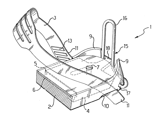
I~ith reference to Figures I Co 5, a generic binding device I
is described, particularly for securing the foot to such a
sporting implement as a roller skate, a water ski, a bicycle pedal,
a ski boot, etc Of course, depending on the specific use, the
binding device I would have different morphological features, an
example whereof is given hereinaEter
The binding device I comprises a bearing structure 2 for a
foot (not shown) and, at the foot ankle, a continuous strap 3
e~tending substantially arcuately across the bearing structure 7,
and being bonded adjustably thereto in the manller to be desc.ibed
hereinafter.
On the structure 2, there is guided slidingly and scopped
adjustably (in a manller known per se and no further shown), in a
longitudinal direction, a slide 4; more particularly, the slide
4 is substantially plate-like and movable within a seat 5 for;ned
" ~29~33~9
in che struccure 2 and being covered ac che top by a covering
place 6, actached co ~he scruccure 2 by a screw 7 passed chrough
an opening 8 in Che slide 4. The struccure 2 has cwo upward
excending elevacions ~ rearwardly chereof which form abutmenc
seacs for the piece or footwear.
Lacerally of che slide 4, chere are formed ;n cne structu~e
2 cwo tnroughgoing seacs 10, confroncing che seaC S and excend-
ing upwardly chroughouC the structure 2, in an oblique upward
and forward direction. Inco the seats 10, there are inserced
juxcaposed end portions 11 of Che scrap 3. The throughgoing seats
10 prevent any movement or che sCrap 3 in che aforesaid longicudinal
direccion.
Two cam-li'.~e guides 12 are formed laterally on the slide ~1,
one on each side, and two counter-guides 13 are rormed on the
strap 3, one on each end portion 11. The cam-like guides 12 and
the counter-guides 13 are in mutual engagement relationship and
so shaped as to rnake a sliding forward movement of the slide 4
correspond to a downward sliding movement of the end portions 1i.
More specifically, the cam-like guides 12 and counter-guides
13 comprise rectilinear parallel ribs formed on the slide 4 and on
the end portions 11 ot the strap 3 at a1l angle Co ei-e longitudirla
sliding direction of the slide 4; advantageou.sly, ~sucll ribs are
spaced apart from one another by a distance substa1ltial1y equal
to the width of an individual rib and inclined on the longitudinal
direction of sliding movement of the slide 4.
The slide 4 is also provided with two sunk side regions 14
flanking the cam-like guides 12.
The binding device 1 also comprises a means of displacing
the slide 4 in the seat 5. That means comprises, for example, a
129~329
lever 15 consisting of a shaped bar with a U-shaped actuating
arm 16, and two side pins 17 bent inwardly and aligned. Engaged
slidingly wich the arm 16 is a hammer head 1S rigid with the
slide 4
The operation of the binding device 1 is as follows.
In order co secure the foot on the bearing structure 2, che
athlete would lower the lever 15 dragging the slide 4 backwards;
the end portions 11 of the scrap 3 are thus caused to slide up-
wards and the scrap 3 is slackened. Should the slackening be
insufficient or eccessive, the athlete can depress the lever 15
further, until the counter-guides 13 on the end portions 11
disengage from the cam-like guides 12 on the slide 4 and locate
instead in front of the sunk regions 14. In this condition, the
athlete can shift the strap 3 manually, according to his/her
requirements; thereafter, he/she would pull the lever 15 partway
up to re-establish the engagement beeween the cam-like guides 12
and the counter-guides 13.
The athlete would now place his/her foot onto the bearing
structure 2 slipping it under the slackened strap 3 from behind
The foot (possibly wit11 a piece of footwear) bears rearwardly
on the elevations 9 On pulling now the lever 15 all the way up,
the strap 3 is tightened unfailingly on the foot
As may be appreciated, a binding device according to the
invention affords quick binding features, simply and
effortlessly on slipping the foot in from the rear. While rapidity
and simplicity are self-evident and command no explanation, as
regards restriction of the effort involved in applying the bind-
ing, it is to be noted that, whereas with traditional devices
the tightening pul] should be applied directly to the strap
1298329
axially tllereor, wiLil the invencive device, the pull force is
exerted through a comfortable lever, at a step-down ratio
(determined by the inclination angle of the cam-like guides)
which is selected to malce the tightening operation as easy as
possible.
Shown in Figure 6 is a slide 4a which is interchangeable
with the slide ~; those parts of the slide 4a which are similar
to the corresponding parts of the slide 4 are designated in the
figure with the same numeral, and will not be described.
In the slide 4a, the cam-like guides 12 (again formed of
rectilinear para].1.el ribs) are formed on two wings 21 linked
pivotally to the slide 4a by means of side pins 22 extending
horizontally lenghtwise and being urged elastically upwards and
outwards by torsion springs 23.
With the slide 4a, adjustment of the tightening tension is
further simplified. In fact, to increase the tightening tension,
it will be sufficient to push (with the strap 3 slackened, that
is, the lever 15 down) the end portions 11 of the strap 3 down-
wards, merely overcoming the force of the springs 23 and causing
one or more ribs to skip betwee11 the cam-like guides 12 and the
counter-guides 13.
As may he appreciated from the ~oregoing descripti.on, a
binding device according to the invention may be ustd to advantage,
following appropriate adaptations, with a range of sporting
implements where a foot is to be secured.
As an example, Figures 7 and 8 show a sport piece of footwear,
in particular a ski boot 30 of the rear entrance type, wherein a
rear wall 31 is tiltable around a pivot 32 to permit of the foot
introduction. A traditiona1 hook 33 holds the wa1l 31 in tl1e
1298329
-- 8 --
tightened position of che binding.
Inside the boot 30, a binding device for releasably securing
the foot ac the ankle comprises a saddle piece 34 held pressed
onto the foot inscep by a strap 35 encircling the saddle piece 34,
which is attached movingly to the boot 30 by a hinge 36.
Guided slidlngly longitudinally in a seat 3S in the sole 37
of the boot 30 is a pla~e-like slide 39 provided laterally with
cam-like guides 40 in engagement with counter-guides 41 on end
portions 42 of the strap 35 which are inserted slidingly into
respective vertical side seats 43 facing the seat 38. The cam-like
guides 40 and the counter-guides 41 are so shaped as to make
backward sliding of the slide 39 cause downward sliding of the end
portions 42 of the strap 35.
The slide 39 is linked operatively to the wall 31, it being
provided with a tie 44 hooked on a forked arm 45 rigid with the
tilting wall. 31 on the remote side from the pivot 32.
On then closing the boot (by linfting the tilting wall 31),
the strap 35 is automatically caused to tighten itseli onto the
saddle piece 34, thus securing the foot.
- On the boot 30, a binding devi.ce according to the invention
would also be advantageously used Co secure the foot toe end.
In the sole 37 of the boot 30, a slide 46 engages slidingly
in a longitudinal seat 47 formed at the foot toe end. Two
horizontal.side seats 48 are formed in the sole 37 at the sides
of the seat 47 and open toward it. In the seat 48 there are
inserted juxtaposed end portions 49 of a strap 50 having heads 51.
The heads 51 of the end portions 49 are provided with respect-
ive counter-guides 52 in engagement with corresponding cam-like
guides 53 formed on the slide 46. The cam-like guides 53 and the
:.
12983~9
counter-guides 52 are shaped such that for~ard siiding of the
slide 46 results in the end portions 49 of the stra? 50 sliding
inwards; advantageously, the carn-li~e guides j3 and the councer-
guides 52 comprise each a plurality of rectilinear parallel ribs
set apart from one another by a distance whicil is substantiall~
equal to the widtil of a singl.e rib and beillg set at a.l angle ce
the longitudinaL sliding direction of the slide 4~.
The slide 46 is connected to the slide 39 by a tie 54,
passed through a hole 55 in the sole 37, and is therefore movable
therewith. Tllus, closing the boot will also res~llt in the strap
50 being tightened.
It will be apparent thac ocher applications of the invencion,
not specifically illustrated, are possible, as are other variancs,
wichouc deviating from the protection scope defined in the
appended claims.