Note: Descriptions are shown in the official language in which they were submitted.
~8.~
MILK FLOW INDICATOR
Field of the Invention
The present invention is generally directed to a
liquid flow indicator placed in a liquid flow passageway,
and particularly directed to a milX flow indicator for
indicating the flow of milk in a system under vacuum, for
example, in a milking system in a milking parlor.
Background of the Invention
Although there are a variety of uses for the device
of the present invention, specific reference to the use of
the present invention in a milking operat;on will be
emphasized. When milking cows, goats or other milking
animals with automated milking apparatus, it is important
to determine the end of the milking period. Generally, the
end of the milking period is determined by observing the
udder being milked, the condition of the milk obtained or
the quantity of milk as it flows in a milk line which has
been provided with a transparent portion. For example,
U.S. Pat. 3,007,436 to Seaborne discloses a mi]k flow
indicator which comprises a sight glass for visual
indication of the end of the milking period. U.S. Pat.
2,697,944 to Wenham also discloses a liquid flow indicator
for a milking machine which indicates visually the state
of milk flow through the indicator. U.S. Pat. 2,513,627
-2-
to Dinesen discloses a flow indicator for a milking
machine having a transparent portion making it possible
for the operator to detect milk flow at all times.
Other methods of determining~the end of the milking
period are also described in the prior art. U.S. Pat.
3,991,716 to Reisgies discloses an apparàtus for sensinq
milk flow from an animal being milked using pneumatic
controls without the use of electrical circuitry. U.S.
Pat. 3,786,762 to Abrahamson et al. discloses a milk flow
~en~ing valve unit compri~ing a float chamber hou~ing a
float member which holds the valve ~pen when the milk is
present to permit milk discharge. When the milk flow
falls below a certain rate, the float lowers and closes
the valve shutting off the vacuum supply causing the teat
cups to fall away. U.S. Pats. 3,973,520 and 4,022,158 to
Flocchini disclose a float detector comprising a
cylindrical flow tube with a metal float. The milk in the
tube causes the float to rise. As the level of milk
drops, the float moves toward a metal detector at the
bottom of the tube. When the float contacts the detector,
a circuit is activated sensing the interruption of milk
flow. If milk flow is then resumed, the float moves away
from the detector and the detection of resumption of milk
flow is resumed. Another patent which uses electrical
sensors to determine liquid flow is U.S. Pat. 4,433,577 to
Khurgin et al. U.S. Pat. 4,348,984 to Brayer discloses a
flow system controller which automatically stops the
milking operation when the flow of milk is decreased. The
milk flow sensor employs a pair of electrodes to sense the
flow of milk. The flow of milk causes an electric current
to flow between the electrodes. When the milk flow drops
off, an output signal stops the pulsator and produces a
warning light. U.S. Pat. 4,306,517 to Nakamura discloses
a milk flow sensor which signals the end of the milking
operation. A pair of electrodes are used for detecting
the quantity of milk flowing through the sensor. An alarm
device signals the end of milking.
l~g8~
U.S. Pat. 4,253,421 to Slater et al. discloses a milk
flow system connected to a stanchion which detects the
flow of milk by means of a counterweight system. When
milk is in the sensor, flow communication is opened
allowing the vacuum system to operate. When the milk flow
drops, the counterweight swings closing off the vacuum
which automatically removes the teat claws.
Summary of the Invention
The present invention i8 directed to a portable and
detachable milk flow sensor which signals milk flow
stoppage by means of an alarm signal and a light. If milk
flow resumes, the signal automatically stops without
requiring any manua] resetting. The electronic circuit
include~ a pair of stainless steel electrodes located in
the path of milk flow activated by a battery powered
source. When the entire milking operation is complete,
the milk flow sensor may be removed from the milking
stanchion and placed on a battery charger device
incorporated into a milkhouse wash manifold.
One of the primary advantages of the present invention
is that the milk flow indicator indicates the absence of
milk repeatedly without having to manually reset the
circuit. In other words, the liquid flow indicator of the
present invention is automatically reset when flow
resumes. This is important, espècially in a milking
operation. Some cows reduce milk flow near the end of
their milking but then resume milk flow for a moderate
period of time. The milk flow indicator can give a brief
indication of "no milk" and automatically reset when milk
resumes. Then, it will give another "no milk" indication
when flow ceases. Thus, the flow indicator of the present
invention reliably signals when a cow is milked out,
alerting the milker to remove the unit. Should flow
resume, the signal ends and the device is ready to detect
the next flow stoppage. Further, the audible and visual
1~98;~Z
_a,_
signals alert the milker to prepare the next cow for
milking.
The flow indicator of the present invention is easy to
attach to any liquid flow line. It does not require any
physical attachment in the way of power cords, vacuum
hoses to the pulsator or pulsator hoses. It is also
compact and portable.
The flow indicator of the present invention also
reduces the tedious job of walking back and forth checkin~
0 COW9. This means improved udder health and more efficient
and consistent milkin~. The milkers will spend less time
determining when the cows are milked out, leaving more
time for proper preparation and teat dippinq.
Further, by using a battery powered energy source, the
voltage in the system is far lower than the line current
powered systems electrical circuits oE the prior ~rt. The
device is also isolated from ground thus eliminating any
stray voltage. This eliminates or at least substantially
reduces the possibility of shocks to the animal and to the
operatorS-
~ primary object of the present invention is toovercome the disadvantages o the prior art.
It is also an object of the present invention to
provide a liquid flow sensor which is useful in
determining the flow of liquid through a passageway or
tube, without obstructing milk flow in any manner.
It is another object o~ the present invention to use a
milk 10w indicator which may be removed and transported
to a combination cleaner/battery charger.
It is another object of the present invention to
provide a battery operated, removable milk flow sensor in
which the si~naling device automatically activates or
deactivates depending upon the level of milk 10w through
a sensor.
1~8.~82
- 4a -
Therefore, in accordance with the present invention
there is provided a milk flow indicator adapted for insertion
in the milk flow line of dairy barn milking equipment. The
indicator comprises a body member formed of a durable
material having a milk flow passageway extending therethrough
and a housing formed into it. Electrical beams are provided
for sensing milk flow received in the bod~ member adjacent to
the passageway. Electrically actuated indicating means
indicates a presence of milk flow in the milk flow
passageway. An electrical circuit is received in and sealed
into the housing for operating the sensing means and the
indicating means to sense milk flow and indicate the status
of the flow. A rechargeable battery is received in the
indicator and is electrically connected to the electrical
circuit but isolated from ground and external electrical
connections so that the indicator is portable and
self-contained and can be inserted independently in the milk
flow line without electrical connection and still indicate
condition of milk flow. Contacts are mounted on the external
surface of the indicator and are electrically connected to
the battery so that the battery can be recharged by external
power without removal from the indicator.
Other objects, advantages and features of the present
invention will be apparent from the following specification
when taken in conjunction with the accompanying drawings.
1~8;~
--5--
Description of the Drawings
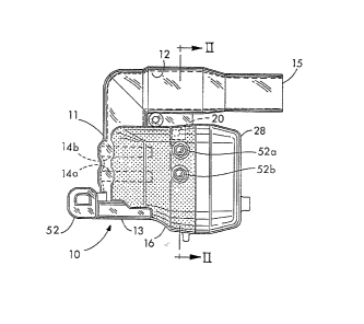
FIG. 1 is a side elevation view of a milk flow
indicator constructed in accordance with the present
invention.
SFIG. 2 is an end elevation view of the milk flow
indicator of Fig. 1 with the cover removed.
FIG. 3 i8 an exploded side elevation view of the milk
flow indicator of Fig. 1.
FIG. 4 is a perspective view of the milk flow
indicator of Fig. 1 as placed on a wash manifold.
FIG. 5 is an end elevation view of the indicator and
manifold of Fig. 4.
FIG. 6 is an electrical schematic diagram of the
circuit of the indicator of Fig. 1.
15Detailed Description of the Invention
The device of the present invention is a portable and
detachable milk flow sensor which signals milk flow
stoppage by a visual and audible alarm signal. In a
milking operation, the device of the present invention is
placed between the claw and the main milk line and serves
to indicate when the milk flow from each cow reduces to
the point where the teat cup should be removed. If the
milk flow should resume after the initial reduction, the
signal automatically stops without requiring any manual
resetting. When the entire milking operation is complete,
the flow indicator may be removed from the milking
stanchion and placed on a battery charger device
constructed as a part of the milk wash manifold.
The device of the present invention will now be
described with reference to Figs. 1-6, wherein like
reference numerals will refer to the same features
throughout the drawings. Referring now to Figs. 1-6, a
self contained, battery-powered milk flow indicator 10 is
shown. In a milking operation, one milk flow indicator 10
~8;~
is designed to be placed between a milking teat claw and
the main milk line (not shown) to indicate when the milk
flow from each cow reduces.
The flow indicator 10 has as its largest component a
body member 11 which has formed in it a milk passageway 12
having an inlet 15 and an outlet 13. The diameter of the
outer wall of the passageway 12 near the outlet 13 may be
reduced somewhat in order to enable conventional milk line
tubing to be attached thereon. The body member 11 of the
milk flow indicator 10 also includes a housing 16 which
houses the electrical circuit of the device of the present
invention, and a battery cover 2~. The body member 11 of
the flow indicator 10, including the passageway 12 and the
housing 16, is molded in a unitary structure of rigid,
durable, preferably translucent material, such as a
synthetic resin or plastic.
The flow indicator 10 has mounted inside of it a pair
of conductive annular electrodes 14a and 14b respectively
mounted in parallel, spaced-apart relationship on the
inner circumferential periphery of the passageway 12 and
jointly functioning as a conductivity electrode or
electric flow sensor 14. The flow sensor 14 provides an
electrical conducting path through the milk when milk
flows through the passageway 12 and has a conductivity
through the milk, which is lower or higher in accordance
with the flow of the milk. As milk continues to flow in
the passageway, the conductivity is high. However, as
milk flow reduces, the conductivity becomes low.
An electrical circuit is located on a circuit board
sealed in the housing 16 of the liquid flow indicator 10,
and is held sealed in place in the housing 16 by a
non-conductive, moisture proof, potting compound, of which
many types are commercially available. Besides holding
the electrical circuit in place, the potting compound
provides a noncorrosive, liquid-tight protective cover for
the electronic circuit. The detail of the electrical
circuitry will be explained further on in the
~9~
specification with re~erence to Fig. 6, Briefly, the
electrical circuitry monitors the flow of milk through the
sensors 14 in the passageway 12 and senses when this flow
has substantially stopped. The milk flow is sensed by
passing an electrical current through the mi]k between
electrodes 14a and 14b to detect the presence of milk.
When the milk flow has stopped, the passageway 12 empties
thus reducing the electric current.
Reducing the flow of the electric current activates an
alarm device which signals the end of the milking period.
The alarm is both audible and visual. The audible alarm
is in the form of a 4-5 second beeper, known to the art,
connected to the electrical circuitry. A speaker or
beeper 18, shown in Fig. 2, emits a sound loud enough to
alert a technician that the milking period is over.
Additionally, a flashing light in the form of a
light-emitting diode or LED, generally located at 20, is
used to alert the technician. The LED 20 is positioned on
the circuit board sealed in the housing 16 so that it is
adjacent to the inside of the housing 16 so that it i5
visible from the exterior of the housing 16 when it is
illuminated. Preferably there are two LED's 20, one on
each side of the indicator 10. In operation, the end of
the milking period is si~nified by both a beeping alarm
sound and a flashing light. After 4-5 seconds, the
audible alarm terminates, leaving the light flashing until
milk flow resumes in the passageway 12, either by a
resurgence of milk by the present animal or by connecting
up a new animal to the system.
The liquid flow indicator 10 is preferably powered by
a small rechargeable 7.2 volt battery 22 which is
connected to positive and negative battery terminals 24a
and 24b within a battery chamber 26 under the battery
cover 28. When the battery 22 is in place, the battery
cover 28 snaps onto the housing 16 of the liquid flow
indicator 10. The battery cover 28 further includes a
channel 30 which connects the beeper 18 to the exterior of
the indicator 10 through a diaphragm 31 when the battery
cover 28 i9 in place. The diaphragm 31 isolates the
beeper 18 from water and debris while allowing
transmission of sound. The channel 30 provides a resonant
cavity allowing and enhancing expression of the alarm
sound from the beeper 18. The resonant cavity of the
channel 30 is in the form of a slot approximately .312 by
.375 by 1 inches.
A flow rate adjustment potentiometer 40 is provided
within the housing 11 of the liquid flow indicator lO.
Adjusting a set screw in the potentiometer 40 determines
the sensitivity of the end-of-milk signal. The
potentiometer 40 is operated by turning the set screw
clockwise in order to allow a longer milking time before
an alarm signal and turning counter-clockwise in order to
allow a shorter milking time. A removable plastic plug 42
is placed on top of the set screw to prevent moisture
damage to the potentiometer and the other electrical
components and to prevent inadvertent turning of the set
screw in the potentiometer.
Shown in Fig. 6 is a schematic diagram of the circuit
for the milk flow indicator of Figs. 1-3 which can be
constructed on a circuit board to be incorporated in the
housing 18. The circuit on the circuit board in the milk
flow indicator also includes connections (not shown) to
the battery. The battery output is connected to a
regulated power supply integrated circuit (also not shown)
in a manner well known to the art to generate a fixed
voltage from ground for the remaining circuit elements of
Fig. 6. In the circuit of Fig. 6, a multi-vibrator 70,
which is a pulse train generating circuit, is provided
with appropriate capacitors and resistors arranged to emit
a constant, stable pulse train output signal. The pulsing
output o~ the multi-vibrator 70 is connected through a
coupling capacitor 72 and a clamping diode 74, intended to
clamp the voltage below supply, to the milk sensor 14 in
one of two manners.
Z
_9_
In one variation, shown in Fig. 6, the output of the
multivibrator 70 is connected into one side of the primary
of a transformer 76, the other side of which is connected
to the non-inverting input of a comparator 78. The
secondary of the transformer 76 is connected through
suitable physical connectors to the milk flow sensor 14
which, although physically composed of the spaced
electrodes 14a and 14b, is represented in the electrical
schematic view o Fig. 7 as a variable resistor. In a
second variation, indicateA by a dashed box located below
the transformer 76 in Fig. 6, and to be substituted in the
circuit for the dashed box containing the transformer 76,
the transformer 76 is replaced by a resistor 77 connected
in parallel with the electrodes 14. The resistor 77 may
be used in most applications, although the transformer 76
may be needed if the circuit is in any way grounded, to
avoid stray voltage through the milk line.
A resistor 81 connected to the supply voltage and a
noise reduction capacitor 80 are also connected to the
non-inverting input of the comparator 78. The inverting
input of the comparator 78 is connected to a resistive
hridge 82 so that it is held at a fixed voltage. In
function, the pulse train, which is the output of the
multi-vibrator 70, is coupled through the capacitor 72 and
to a series circuit composed of the resistor 81 in series
either with the transformer 76, or with the parallel
resistors 77 and 14. If there is conductivity between the
secondary electrodes of the electrodes 14a and 14b, which
is the case when milk is flowing between the electrodes
14a and 14b, then the negative going pulses are applied
into the non-inverting input to the comparator 78 to
reduce that input to a voltage less than the reference
voltage on the inverting input, thereby causing the output
of the comparator 78 to switch. ~hen milk is not flowing,
the negative pulses from the comparator 78 are attenuated,
since the resistance of the sensor 14 is high, so that the
pulses never drop below the reference voltage and the
--10--
output of the comparator 78 remains high. Thus the output
of the comparator is a pulse train consisting of a series
of negative pulses if, and only if, there is milk flow
through the milk passageway 12 between the electrodes 14a
and 14b.
The output of the comparator 78 is connected to the
input of a retriggerable one-shot 84, which functions as a
retriggerable time delay circuit creating a timed output
pulse when triggered or retriggered. The ti~ing inputs to
the one-shot 84 consist of a pair of capacitors 86 and 88
which are connected in parallel in a series with a pair of
resistors 9O and 92 which are in turn further linked in
series with a variable resistance in the form of the
potentiometer 40. Potentiometer 40 is the same
potentiometer whose resistance may be adjusted hy
operation of the screw illustrated in Fig. 2. The
resistive and capacitive values in the timing circuit
connected to the one-shot 84 are selected so as to provide
a timed pulse output of the one-shot 84 which is variahle
in length between 1.75 and 4.5 seconds, depending on the
setting of the potentiometer 40. The one-shot 84 is
therefore programmed to emit a pulse instantly upon the
commencement of milk flow activity, as indicated by a
pulse output from the comparator 7B, and to maintain that
pulse output, because it is continuously retriggered, for
as long as milk flows through the indicator 10. If milk
flow should cease for a time period less than the time
period of the one-shot 84, the one-shot ~4 would not time
out and would be retriggered by the next subsequent pulse
indicating milk flow. If milk flow ceases for a time
period longer than the pulse time, the one-shot 84 would
then time out. Thus the period of absence of milk flow
used to indicate a cessation of milk flow from the animal,
can be adjusted by the setting o the potentiometer 40.
The inverted output of the one-shot B4 ;s connected
through a pair of resistor and diode series connected in
parallel. Resistor 96 and diode 9B, with the anode of
--ll--
diode 98 toward the one-shot 84, is active when the
one-shot 84 turns off, or when i~s inverted output is
high, to charge a capacitor 104 to which resistor 96 is
connecte~. The resistor 100 and the diode 102, with its
cathode toward the one-shot 84, will be active when the
inverted output of the one-shot 84 is low to discharge the
capac;tor 104. Both of the resistors 96 and 100 are
connected to the capacitor 104 the other side of which is
connected to ground. Thus the combination of the
resistors 96 and 100 and the diodes 9~ and 102, in
conjunction with the capacitor 104, makes an RC timing
network that provides a time delay during turn on or turn
off of the output of the one-shot 84. The output of the
one-shot 84, sub~ect to this time delay, is coupled
through the resistor 106 to the non-inverting input of
another comparator 108. The inverting input to the
comparator 108 is also held at a fi~ed voltage by a
resistive bridge consisting of two resistors 110. A
capacitor 107 is connected to ground for noise re-3uction.
The output of the comparator 108 is also linked back
through a resistor 112 to its non-inverting input. In
essence, when the one-shot 84 is triggered, its inverted
output goes low, which discharges the capacitor 104
through the resistor 100 and diode 102, and drags the
non-inverting input to the comparator lO8 low. At that
point the output of the comparator 108 then goes low an~
further reinforces the low con~ition through the feedback
resistor 112. When the one-shot 84 times out, as when
there is no milk flow, its non-inverting output goes high,
which charges the capacitor 104 through the diode 98 and
the resistor 96, which brings the non-inverting input to
the comparator 108 high, thereby causing the output of the
comparator 108 to go high, which further feeds upon itself
through the resistor 112. Thus the output of the
comparator 108 is the logical inverse of milX flow in that
its output i9 high when there is no milk flow and low when
there is milk flow.
1~8;~Z
-12-
A pair of light-emitting diodes (LEDs) 112 located in
series with limiting resistors 114 serve as the visual
ind;cation of the condition of milk flow. The cathode of
both of the LEDs 112 are connected through a transistor
1]6 to ground. The base of the transistor 116 is
connectea through diode 118, which is connected in
parallel with resistors 120 and 122, to the output of the
comparator 108. The base of the transistor 116 is
connected, in addition, to the output of another
multivibrator 71. The base of the transi~tor 116 is also
connected through a transistor 124 to ground, with the
base connection to the transistor 12~ being connected
through a resistor 126 to the output of the multi-vibrator
70. The output of the multi-vibrator 70 is thus conducted
through the transistor 124, which continually switches on
and off. This switching of the transistor 124 will switch
the transistor 116 continually on and off, if not clamped
off by the comparator 108. If the output of the
comparator 108 is high, indicating no milk flow, the
switching of transistor 116 is not clamped and that is
precisely what happens. The switching of the transistor
116 causes current pulses to flow through the LEDs 112
thereby providing a flashing visual indicator of no milk
flow. If the output of the comparator 108 is low, that
output, coupled through the diode ]18, will clamp the
transistor 116 off thereby preventing current flow through
the LEDs 112 and holding those LEDs off.
The output of the comparator 108 is also connected to
the input of a second one-shot 128, which has connected to
it suitable resistive and capacitive timing components to
give it a timed output of approximately four seconds. The
non-inverted output of the one-shot 128 is connected to
the base of a transistor 130 whose emitter is connected to
the collector of the transistor 116 and whose collector is
connected through the beeper 18 to the supply voltage.
Thus, when the output of the comparator 108 goes high,
indicating the end of milk flow, the one-shot 128 is
1~9~
-13-
triggered on for a four second time period. During that
time period, its output is high thereby turning on the
transistor 1~0, and allowing current flow through the
beeper 118, as also controlled by the transistor 116.
Since the transistor 116 is switching on and off, the
sound from the beeper is a series high frequency pulses
whose pulse frequency is determined by the multivibrator
71 and whose sound is controlled by the speed of the
multi-vibrator 70. At the end of four seconds, the
one-shot 128 time~ out, and the beeper 118 turns off. The
visual display of the flashing LEDs 112, while the milk
flow is low or stopped, will continue as long as the
circuit is connected to a supply vo]taqe.
Thus, essentially the comparator 108 and the
transistors 116, 124, and 130 function as a switching
circuit to turn on the audihle and visual indicators, the
beeper 18 and the LED's 112, in response to the signal
from the one-shot 84.
Thus the circuit of Fig. 6 is intended to accomplish
the following ob~ectives. The circuit allows for milk to
cease flowing for an adjustable period of time before
signaLing an alarm indicating end of milk fIow. This
feature is accomplished by the retriggering of the
one-shot 84 and the fact that the indication of end of
milk flow does not occur until the one-shot 84 times out.
If at any time during the timing period of the one-shot 84
milk flow i9 sensed again, the one-shot will be
retriggered and the delay period will restart. Thus the
circuitry never indicates no milk if milk flow resumes
during that time period. In addition, the circuit never
needs to be reset. This means that even ater an audible
and visual signal of no milX flow has occurred, if milk
flow resumes, since one-shot 84 is promptly triggered and
its effects cascade through the comparator 108, the signal
of no milk flow is removed, only after the time delay of
the resistor 100 and the capacitor 104, without the need
for any additional resetting or operation by the user.
i2~
-14-
One of the major benefits of the self-contained liquid
flow indicator 10 resides in its portability. When the
milking operation is complete, the liquid flow indicator
10 may be easily removed from the milking line and placed
on a wash manifold 50, illustrated in Figs. 4 and 5, which
incorporates a battery charger 60 therein. The wash
manifold 50 i9 a piece of equipment found in the typical
milkhouse adjacent to a milking parlor for cleaning
milking equipment. The manifold 50 i8 a conduit through
which hot, disinfectant fluids may be conducted to clean
milking equipment. The mating ~ittin~ 52 located on the
exterior of the indicator 10 is intended to mate with a
common style of wash manifold fitting. The wash system
may include other pipes or tubing to connect to the outlet
15 of the inciicator 10 so that cleaning fluid may pass
through the passageway 12 and be recovered.
While the liquid flow indicator 10 is being cleaned,
the power source is automatically charged by the battery
charger 60. Referring now to Figs. 1 and 3, there is
illustrated two contacts 52a and 52b which are connected
to the contacts 24a and 24b which contact the battery 22.
Preferably, the battery power source is a rechargeable
source, such as a nickel-cadmium (NICAD) rechargeable
battery. The battery charger 60 is mounted beside the
wash manifold 50 in such a manner as to contact the
contacts 52a and 52b when the milk ~low indicator 10
itself is placed on the wash manifold for its normal daily
cleaning.
The battery charger 60 is illustrated having a base 62
for securing the battery charger 60 on the washing line
alongside the wash manifold 50. The battery charger 60
includes a printed circuit board 64 on which are located
sealed components (not shown) to rectify and transform
conventional AC power supply voltage levels to a DC
voltage suitable to the battery 22. The DC voltage thus
produced is connected to a pair of contact arms 54a and
54b. When the indicator 10 is placed correctly on the
Z
wash manifold 50, arms 54a and 54b will be in contact with
contacts 52a and 52b. The battery charging device is
connected to standara farm electrical supply by means of
connecting wire 55. It is within the scope of the present
invention to provide a series of wash manifold/battery
charger which may be cleaned and charged simultaneously.
The battery 22 in the indicator 10 is thus automatically
and easily recharged daily as the indicator 10 is cleaned
in its normal operation. Thus the indicator 10 is
normally always near full charge and ready for use without
parti~ular attention to it.
Although the present invention has been described with
preferred embodiments, it is to be understood that
modifications and variations may be resorted to without
departing from the spirit and scope of this invention, as
those skilled in the art will readily understand.