Note: Descriptions are shown in the official language in which they were submitted.
~Zg911~
STEREO SYNTHESIZER
8ACKGROUND OF THE INVENTION
1. Field of the Invention
The present invention is an improvement on the
stereo enhancement system of my U.S. Patent No.
4,748,669, issued May 31, 1988, and enables my prior
invention to be used with a monaural input signal. The
present invention relates to an improved feature of the
generation of synthetic stereo signals from a monaural
signal and more particularly relates to synthetic
generation of sum and difference stereo signals of a
type which provide useful stereo information to a stereo
enhancement system.
.~
lZ9911~
1 2. Description of Related Art
In many stereo sound systems the circuits merely
amplifv right and left channel signals and feed these to
loudspeakers. In my above-identified co-pending applica-
tion, stereo signals such as sum and difference signalsare processed to provide image enhanced stereo output sig-
nals to a stereo speaker system. In these systems and
other stereo systems it is necessary that a stereo input
be provided if a stereo output is to be produced.
Generally such a stereo input is available either in the
form of left and right stereo input signals, or, as in
some broadcast systems, in the form of the sum (L + R) of
left and right stereo signals and the difference (L - R)
between such left and right stereo signals. In a common
type of stereo signal broadcast system, left and right
stereo signals are combined at the broadcast station
before transmission. A sum signal (L + R) is modulated
upon a main carrier, and a difference signal (L - R) is
modulated upon a higher frequency sub-carrier. Generally
the sub-carrier is weaker than the main carrier, and
transmission of the stereo signals is frequently along
multiple paths due to the bouncing of the FM transmission
between or among buildings or other obstacles. This
causes the difference signal transmitted on the weaker
sub-carrier to be considerably weaker at a receiving sta-
tion, varying in intensity, and fading in and out accord-
ing to location of the receiver. When such a receiver is
mounted in a moving vehicle, it may occur that the dif-
ference signal received is so weak as to be substantially
useless. For such conditions some receivers are arranged
to ignore the weak difference signal and to receive,
process and transduce through its loudspeakers solely a
monaural signal in the form of the sum (L + R).
lZ99~1~
Therefore, where the difference signal is too weak
or absent, the listener will only be able to receive and
hear a monaural sound. This is so even if the receiver
should include effective and sophisticated stereo image
enhancement circuitry, such as described in detail in my
above-identified co-pending application. Only in the
presence of a stereo input will certain image processing
circuits, such as the stereo enhancement system of my
prior application, be able to perform the desired
enhancement.
In other situations only a monaural signal is
produced, but stereo sound is desired. For example,
when playing a monaural record in a stereo playback
system, it would be desirable to provide both left and
right stereo signals to the system amplifier, whether or
not any enhancement circuitry is employed. So, too,
when a vocalist or individual instrumentalist provides
sound to only a single microphone, it may be desired to
provide stereo sound from the single monaural signal.
Therefore it is desirable to enable a receiver, a
playback system, a recording system, or any other sound
system, to provide stereo sound even though but a single
signal, a monaural signal, is available.
Accordingly, it is an object of an aspect of the
present invention to provide a stereo image enhancement
system capable of use with a monaural input.
SUMMARY OF THE INVENTION
In carrying out principles of the present
invention, in accordance with a preferred embodiment
thereof, stereo output signals are generated from an
input signal by producing simulated or synthetic sum and
difference signals in response to the input signal. The
synthetic difference signal is delayed with respect to
the synthetic sum signal and has components of different
frequencies, each having a different time delay relative
l'~9glll
to components of like frequency of the synthetic sum
signal. The synthetic sum and difference signals are
fed as stereo inputs to a stereo image enhancement
circuit. According to a feature of the invention, the
simulated difference signal is provided by shifting the
phase of the input signal with a phase shift that is
constant over a broad frequency range so that the
simulated difference signal lags the input signal and
diffexent frequency components of the simulated signals
have different amounts of delay.
According to another feature of the invention,
stereo output signals are generated from an input signal
by employing the input signal to produce simulated sum
and difference signals and feeding the simulated signals
to stereo image enhancement means. The stereo image
enhancement means is arranged to selectively alter
relative amplitudes of components of the simulatad
difference signal within respective predetermined
frequency bands so as to boost difference signal
components in relatively quieter difference signal
frequency bands and to selectively attenuate relative
amplitudes of components of the sum signal within said
quieter difference signal frequency bands.
Other aspects of this invention are as follows:
A system for generating stereo image enhanced
output signals from a monaural input signal having a
bandwidth, said system comprising:
first means responsive to the monaural input signal
for generating a simulated sum signal which comprises
different frequencies,
second means responsive to the input signal for
generating a simulated difference signal that is delayed
with respect to said simulated sum signal and which has
components of said different frequencies, each such
component in said second means having a different time
delay with respect to a corresponding component in said
.~'
~Zg91~
5a
first means, said first and second means comprising
phase shift means for providing each different delay
time as a substantially fixed phase sPparation between
corresponding bands of said simulated sum and said
simulated difference signals over at least a portion of
said bandwidth, and
stereo image enhancement means responsive to said
simulated sum and difference signals for generating
stereo enhanced left and right output signals.
The method of deriving ætereo enhanced signals from
a monaural input signal comprising the steps of:
generating a simulated sum signal from said input
signal by shifting the phase of said input signal by an
amount that is substantially constant over a broad band
of frequencies,
generating from said input signal a simulated
difference signal that is delayed with respect to said
simulated sum signal and which includes components of
different frequencies each having a delay relative to a
component of like frequency of said simulated sum signal
that is different than the delay of another frequency
component of said difference signal relative to another
frequency component of like frequency of said simulated
sum signal said step of generating a simulated
difference signal comprising shifting the phase of said
input signal by an amount that delays said simulated
difference signal by about 90 relative to said
simulated sum signal,
equalizing said simulated sum and difference
signals to provide stereo image enhanced stereo signals,
and
generating left and right stereo output signals
from said stereo signals.
A system for generating stereo output signals from
a monaural input signal, said system comprising:
~Z9~1111
5b
first phase shift means responsive to the input
signal for generating a simulated sum signal,
second phase shift means responsive to the input
signal for generating a simulated difference signal,
and
stereo image enhancement means responsive to said
simulated sum and difference signals for generating
stereo enhanced left and right output signals, said
stereo image enhancing means comprising:
means for selectively altering relative amplitudes
of components of said simulated difference signal within
respective predetermined frequency bands so as to boost
difference signal components in relatively quieter
difference signal frequency bands,
said first and second phase shift means comprising
a constant phase shift circuit having first phase shift
channel means responsive to said input signal for
generating said synthetic sum signal with a phase that
is shifted relative to phase of said input signal, and
having second phase shift channel means responsive to
said input signal for generating said synthetic
difference signal with a phase that lags the phase of
said synthetic sum signal by about 90 over said
predetermined frequency bands, and
means for selectively altering relative amplitudes
of components of said input signal within said
respective predetermined frequency bands.
BRIEF DESCRIPTION OF THE DRAWINGS
In the accompanying drawings:
FIG. 1 is a simplified block diagram of a system
embodying principles of the present invention;
FIG. 2 is a circuit diagram of an exemplary
constant phase shift circuit;
....
~ f ' ' ,~ ~
~Z991~1
1 FIGS. 3 and 4 illustrate characteristics of op-
tional filters for use in connection with a phase shift
circuit of FIG. 2;
PIG. 5 is a block diagram showing additional
details of the system of FIG. 1 as used with a radio
receiver;
FIG. 6 is a simplified block diagram of a
modification of the circuit of FIG. l; and
FIG. 7 illustrates another use of the system of
FIG. 1.
DESCRIPTION OF THE PREFERRED EMBODIMENT
.
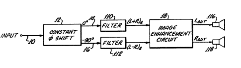
As illustrated in FIG. 1, an input signal on a line
10 iB fed to a constant phase shift circuit 12 having cer-
tain desired characteristics. This phase shift circuitprovides a pair of outputs on lines 14,16 respectively,
which exhibit a 90 phase difference with respect to one
another. Therefore, the signal on line 14 may be labeled
0, and that on line 16 may be labeled -90, solely to
identify the phase of the signal on line 14 relative to
phase of the signal on line 16. Neither of the signals on
lines 14 and 16 is necessarily related to the input on
line 10 by either 0 or 9O. The phase relation of the
circuit outputs to the input is not important. Only rela-
tive phase of the two circuit outputs must be controlled.Characteristics of the constant phase shift circuit 12 are
such that a substantially constant 90 phase saparation
between signals on line 14 and the signal on line 16 ex-
ists at all freguencies over the audio band. That is, be-
tween the frequencies of about 100 Hertz and 15 Kilohertzall frequencies of outputs on lines 14 and 16 have a sub-
stantially 90 phase difference. Amplitude response is
relatively flat at all such frequencies. Accordingly,
1~99~
1 since the phase separation is relatively constant over all
frequenciee, it follows that the time delay of any one
frequency of the signal on line 16 with respect to any
second frequency of the signal on line 16 will be dif-
ferent than the time delay of such one frequency withrespect to a third frequency. In other words, the several
frequency components of the signal on line 16 each have a
different time delay relative to the other frequency com-
ponents of this signal so that the several frequency com-
ponents of the synthetic difference signal on line 16 areeffectively spread out in time. The same is true for the
simulated sum signal on line 14. Thus there is a dif-
ferent time delay between corresponding frequency com-
ponents of the simulated signals at different frequencies.
The time delays of the several components vary with the
frequencies of such components.
Importantly, the several frequency components of the
syntheti~ difference signal are delayed by different
amounts relative to components of corresponding fre-
quencies of the synthetic sum signal. For example, thetime delay of a synthetic difference signal component of
1000 Hertz relative to a synthetic sum signal of 1000
Hertz is greater than the time delay of a synthetic dif-
ference signal component of 2000 Hertz relative to a syn-
thetic sum signal component of 2000 Hertz. Therefore,this time spreading of frequency components provides an
effective simulation of a stereo difference signal. The
entire signal, that is, all the frequencies of the ignal
on line 16, will lag all corresponding frequencies of the
signal on line 14 by about 90.
With the described outputs of the constant phase
shifter 12l the signal on line 14 may be considered to be
the stereo sum signal (L + R), and the signal on line 16
~z99~
1 may be considered to be a stereo difference signal (L -
R). Because both outputs have been phase shifted (as will
be described below), both may be termed synthetic, and are
labeled (L + R)g and (L - R) 8 in the drawings (after being
filtered). However, the phase shifting (or any other
processing) of the sum signal on line 14 is not necessary,
except as needed to obtain the desired lagging phass rela-
tion of the synthetic difference signal on line 16. These
synthetic sum and difference signals provide stereo infor-
mation by virtue of the fact that the 0, or sum signal,on line 14 leads the -90, or simulated difference signal,
on line 16. Therefore the sum signal is heard before the
difference signal. This relation serves to emphasize (to
the human ~ar) the central localization of center stage
performers, such as soloists or vocalists. Different dif-
ference signal frequency components are spaced from their
corresponding frequency components of the synthetic sum
signal by different increments of time which depend upon
frequencies of the several components. Because the dif-
ferent frequency aomponents of the simulated differencesignal (L ~ R)s have different delays relative to cor-
responding frequency components of the simulated sum sig-
nal (~ ~ R)s, th~re iB created, for the listener, an illu-
sion o~ a spread out sound stage. This is an effective
~ynthesis of stereo sound.
The dlfference signal on line 16 is truly different
from the sum signal on line 14, and thus the two signals
may be processed by the stereo image enhancement circuit
18 in the manner to be described below.
3Q Although positional information is not preserved in
the signal on line 14, the described synthetic signal gen-
eration circuit creates an illusion of signal spread and
lZ9911~
1 ambience ~by the simulated difference signal), and at the
same time maintains an illusion of a soloist or vocalist
at center stage (by the sum signal on line 14).
Circuits for maintaining a substantially constant
phase shift and flat amplitude response over the audible
hearing range, such as between 100 Hertz and 15 Kilohertz,
are well known and several differen~ circuits of this type
may be employed in the practice of the present invention.
For example, such a circuit is shown in U.S. Patent
103,541,266 for Bandwidth Compressor and Expander and in an
article entitled "Outputs of op-amp networks have fixed
phase difference" by Richard K. Dickey in pages 129, 130
of the Designers Casebook, Edited by Electronics and pub-
lished by McGraw Hill.
15FIG. 2 illu~trates an exemplary constant phase shift
circuit that has been used in the present invention. In
this circuit a monaural input signal on line 10 is fed via
an input capacitor 20 and a voltage following differential
amplifier 22 to first and second phase shift channels
having inputs on lines 24 and 26 respectively from the
output of the voltage following amplifier 22. Each of the
channels of the phase shifter, the upper (first) channel,
and the lower (second) channel, effectively provide a
phase shift of the output of amplifier 22 that is substan-
tially constant over the desired frequency band. The out-
put of the upper channel at an output terminal 30 has some
predetermined phase relation with respect to the input
signal on line 10. Moreover, the output of the lower
channel on terminal 32 also has a predetermined phase
relation with respect to the input signal on line 10, but,
in addition, has a fixed 90 lagging phase xelation with
~'~9~
l respect to the output signal of the upper channel at ter-
minal 30. This ~0 layging phase relation is substan-
tially constant over the frequency band of interest.
Referring now to the upper channel of FIG. 2, the in~
put signal is fed to a fir~t differential amplifier 40,
being fed to its non-inverting input via an adjustable
resistor 42 and an RC network 44,46 having a selected time
constant. The same input signal on line 24 is also fed
via a fixed resistor 48 to the inverting input of the
amplifier to which the amplifier output is fed back via a
fixed resistor 50. ~he circuitry connected directly with
the differential amplifier 40 provides a 90 phase shift
over a relatively narrow frequency band, such as, for ex-
ample, 50 to 500 Hertz, with a so shift occurring sub-
stantially at the musical center (about 200 Hertz) of thisfre~uency band. The output of the first phase shift stage
is fed to the inputs of a second phase shift stage com-
prising a second differential amplifier 52, having its
output fed back to its inverting input via a fixed resis-
tsr and having the input signal fed to its inverting inputvia a second fixed resistor. The non-inverting input of
the amplifier 52 receives the output signal of the preced-
ing stage via a variable resistor 56 and an RC network
58,60 to provide from this stage a phase shift of 90 sub-
stantially at the center (about 1675 Hertz) of a secondfrequency band having a band width from about l,000 to
5,000 Hertz.
A third stage of phase shift over a bandwidth of
about 5 Kilohertz to 50 Kilohertz provides a 90 phase
shift substantially at the center (about 20 Kilohertz) of
this band. This third stage is provided by a third dif-
ferential amplifier 64 having the output of the preceding
stage fed through a fixed resistor to its inverting input,
lZ99111
1 to which the amplifier output is fed back by a similar
fixed resistor. The preceding stage input is also fed to
the non-inverting input of amplifier 64 via a variable
resistor 66 and an RC circuit 68,70.
Output of the final stage is fed through a capacitor
72 and via a resistor 74 to an output terminal 30.
The RC circuits connected to the non-inverting inputs
of the several amplifiers are the circuit components which
primarily determine the amount of phase shift and the fre-
quency band of operation of the individual stages. Thus
the values of these RC circuit components primarily deter-
mine the phase characteristics of the resultant output.
In an exemplary embodiment resistors 44,58 and 68 are 36
Kilohms, 18 Kilohms and 10 Kilohms, respectively.
Capacitors ~6, 60 and 70 are .02 microfarads, .005
microfarads, and .0005 microfarads, respectively. The
vaxiable resistors are each 5 Kilohms.
It will be readily appreciated that the ideal of a
perfectly constant phase shift over the entire frequency
range of 100 Hertz to 15 or more Kilohertz is only ap-
proximately achieved by breaking the frequency band of in-
terest into three ~eparate bands and employing different
phase shifting aircuits for operation in each of such of
such bands~ Thus within each of such bands the phase
Z5 shift provided by the particular stage is not constant
over the bandwidth of the individual band (being 90 at
the musical center of the band), but the approximation of
the totality of three separate stages distributed over the
entire frequency band as described above is adequate to
provide what may be effectively termed a phase shift that
is con tant over the entire frequency band. If more
precise adherence to a constant phase shift over the fre-
~99111
12
1 quency band is desired, this may be achieved merely by in-
creasing the number of individual stages and narrowing the
frequency bands.
The lower channel of the phase shifter is identical
to the upper channel except for a different choice of com-
ponent values, which provides the 90 lag of the output of
this channel relative to the output of the upper channel.
Thus the lower channel also has three stages, including
differential amplifiers 80,82 and 84, each receiving an
input to its inverting input via a fixed resistance and a
fixed feedback resistor from the output of the preceding
stage, or, in the case of amplifier 80, from the input
signal itself. Each of the amplifiers also receives an
input to its non-inverting input via a variable resistance
and an RC network. The several RC networks are identified
as including resistor 90 and capacitor 92 for amplifier
80, resistor 94 and capacitor 96 for amplifier 82, and
resistor 98 and capacitor lO0 for amplifier 84. As with
the upper channel, the values of these RC circuit com-
ponents are selected to provide for a 90 phase shift cen-
tered in predetermined frequency bands. Thus the first
stage, including amplifier 80, is set to provide a 90
phase shift centered at about 50 Hertz ~e.g. being exactly
90 at 50 Hertz) over a frequency band of about 20 to 200
Hertz. ~he second stage, including amplifier 82, is set
to provide a substantially constant phase shift centered
at (e.g. being 90 at) 600 Hertz over a frequency range of
between about 200 and 2,000 Hertz, and the third stage,
including amplifier 84, is set to provide a substantially
constant phase shift centered at (e.g. being 90 at) about
5,000 Hertz over a band from about 2,000 to 20,000 Hertz.
To obtain this operation, resistors 90, 94 and 98 are 30,
24 and 15 Kilohms respectively, and capacitors 92, 96 and
~9glll
1 100 have values o~ .1, .01, and .002 microfarads respec-
tively. All resistors connected to the inverting inputs
of all amplifiers of both channels are 100 Kilohms. Each
variable resistor is 5 Kilohms. The output capacitor 72
and resistors 74,76 of the upper channel are 4.7
microfarads, 560 ohms, and 4.3 kilohms, respectively. The
output capacitor 77 and resistors 78 and 79 are 4.7
microfarads, 560 ohms and 1 kilohm, respectively.
Referring back to FIG. 1, the signal on line 14 and
the lagging signal on line 16 are fed to first and second
filters 110,112 at the output of which are provided the
synthetic sum signal (L + R)s and the synthetic difference
signal (~ - R)s. The phase shifting of the input signal
on line 10 is not required for the provision of adequate
stereo. It is only necessary that the synthetic dif-
ference signal have the described phase relation to the
signal representlng the sum signal and also have the
delays that vary with frequency. Any circuit providing
this relation between sum and synthetic difference signal
may be used. It is found most convenient to obtain the
relation between synthetic difference signal and sum sig-
nal by using the described circuit which obtains the
desired phase relation and time delays of different fre-
quency components of the synthetic difference signal by
operating on both channels. Therefore, the processing of
the input signal by the upper channel is employed solely
to obtain the desired relation between the two outputs.
The signal on line 14 may be considered to be the input
signal (on line 10), or its e~uivalent, while the syn-
thetia difference signal has the desired phase lagging
relation.
J~299111
14
1 Filters 110 and 112 are provided for the purpose of
still further improving the synthetic stereo signals. In
some cases, one or the other or both of these filters may
be eliminated if desired. Filter 110 provides a band pass
in the band between about 1,000 Hertz and 4 Kilohertz,
having a peak relative amplitude boost of approximately 2
to 6 dB at about 2 Kilohertz. A curve illustrating an ex-
emplary characteristic desired of filter 110 is il-
lustrated in FIG. 3, showing relative amplitude boos of
about 6 dB at about 2 Kilohertz, falling to substantially
no boost at 1 and 4 Kilohertz respectively. Filter 110
helps to enhance the illusion of the source of the (L +
R)s signal at the filter output as being located at center
stage.
Filter 112, operable upon the synthetic difference
signal, provides a relative boost in low and high bands.
The filter provides a relative boost of up to 6 dB at
about 500 Hertz, falling off to about 2 dB boost at about
200 Hertz and 1500 Hertz, as illustrated in FIG. 4. This
filter also provides a second relative boost of about 6 dB
over the band of about 4 Kilohertz to about 10 Kilohertz,
centered at about 7.5 Kilohertz and falling off to about 2
dB boost at about 4 Kilohertz and 10 Kilohertz. Filter
112 thus helps to provide the illusion of a spread of
z5 sound by providing relative boosts at both lower and
higher bands, but not in the center bands. In effect,
filters 110 and 112 provide fre~uency contouring for the
synthetically generated sum and difference signals so as
to emphasize physiological hearing characteristics with
respect to azimuth. Use of these filters will depend upon
placement of the speakers with respect to the listener.
The center location filter 110 is preferred to help the
listener have the illusion of a front or center stage
129911~
sound. Use of this filter is preferred when using only
side mounted speakers, such as earphones. If a listener
is using only front mounted speakers, the spreading
characteristics of the illusion provided by filter 112
are more desirable. For a listener positioned with
speakers on lines directed laterally outwardly and
forwardly at 45 on either side of the listener, use of
both filters 110 and 112 is desired.
Thus, the two filters provide the synthetic sum
signal (L + R)s (which is effectively the mona~ral input
signal) and the synthetic difference signal (L - R)sl
with the latter being delayed with respect to the former
and also having different frequency components thereof
delayed by different amounts relative to corresponding
frequency components of (L + R)s~ These sum and
difference signals are fed to the image enhancement
circuit 18, which may be identical to the circuitry
shown in my U.S. Patent 4,748,669, identified above, and
which provides left and right output signals (LoUt and
RoUt) to left and right stereo speakers 116,118, all as
described in detail in my U.S. Patent 4,748,669.
FIG. 5 shows an application of the system of FIG. 1
to received stereo broadcast signals and also shows
additional detail of the enhancement circuit, together
with the interconnection of the receiver, synthetic
signal generator and enhancement circuit.
A broadcast station 130 sends stereo signals in the
form of a sum signal ~L + R) and a difference signal
(L - R) modulated upon a carrier and sub-carrier,
respectively, to a receiver 132, which provides signals
(L + R) and (L - R) on lines 134,136. The received
signals are fed via switching or variable gain devices
138,140 to a stereo image enhancement circuit of the
,~r~
1~9911~
16
type set forth in full detail in my U.S. Patent
4,748,669. In general the enhancement circuit includes
a sum equalizer 142 and a difference equalizer 144. The
difference equalizer 144, either statically or
dynamically, selectively alters relative amplitudes of
components of the difference signal within respective
predetermined frequency bands so as to boost these
difference signal components that are in relatively
quieter difference signal frequency bands (e.g. those
frequency bands of a real stereo difference signal in
which amplitudes are relatively lower, as statistically
determined). The quieter difference signal frequency
bands are determined either statistically (for static
equalization) or by sensing circuits (for dynamic
equalization). For use with a synthetic difference
signal, static equalization is preferred. The sum
signal equalizer selectively alters relative amplitudes
of components of the sum signal within the same
frequency bands (e.g. those in which the difference
signal is relatively quieter) but relatively attenuates
these. The difference signal, as equalized by e~ualizer
144, is fed through a gain controlled amplifier 146, of
which the gain is controlled by a control circuit 148,
having inputs from the sum and difference signals at the
output of switches 138 and 140. The control circuit 148
also has a feedback from the processed difference signal
(L - R)p provided at the output of gain control
amplifier 146.
The effect of the control circuit and gain control
amplifier, as described in detail in my U.S. Patent
4,748,669, is to effectively maintain a fixed ratio
between amplitudes of the processed difference signal
(L - R)p and the unprocessed sum signal (L + R). By
this means the image enhancement circuit compensates for
different amounts of stereo in different recordings and
,~'
1299~11
17
for different amounts of stereo from one point to
another within a single recording, all as described in
my U.S. Patent 4,748,669.
Sum and difference signals (L + R) and ~L - R) are
made up of the sum of left and right stereo signals L
and R. If such left and right stereo input signals are
not available, the image enhancement circuit can readily
produce these from the sum and difference signals by
taking the sum and difference of the sum (L + R) and
difference (L - R) signals in sum and difference
circuits 150,152 to provide reconstituted input left and
right stereo signals in the form of Lin and Rin on lines
154,156 respectively. The signals on lines 154,156 are
fed through switches 158,160 to a mixer 162 of the image
lS enhancement circuit. The mixer receives the processed
sum signal (L + R)p and processed difference signal
(L - R)p together with the left and right input signals
Lin and Rin and combines these to provide stereo output
signals LoUt and RoUt on output lines 164,166 which are
fed to left and right speaker systems (not shown in FIG.
5). Switches 158,160 are ganged with switches 138,140
so that the sum and difference circuits 150,152 are
effective to provide signals to the mixer only when real
stereo signals are available. If receiver 132 itself
processes the received sum and differences signals to
provide Lin and Rin directly from the receiver, the sum
and difference circuit 150,152 need not be used and the
signals Lin, Rin may be fed directly from the receiver
through switches 158,160 to the mixer 162.
The system operates as described above and as de-
scribed in my U.S. Patent 4,748,669 when both broadcast
signals (L + R) and (L - R) are of adequate strength. The
~Z99111
18
l described circuit, however, also includes the cGnstant
phase shift circuit 12, identical structurally and func-
tionally to the similar circuit of FIG. 1, together with
its filters 110 and 112 to provide synthetic (L + R)s and
(L ~ R)s signals, which are also fed as second or alterna-
tive inputs to the respective switching devices Sl and S2,
indicated at 138 and 140 respectively. The received sum
signal (L + R) is fed as the input to t~e constant phase
shift circuit.
If the broadcast sum and difference signals (L + R)
and (L - R) are of adequate strength, the synthetic stereo
generating circuit, including phase shifter 12 and filters
110 and 112, are effectively disabled. The switches 138
and 140 remain in a position in which only the broadcast
signals (L + R) and (L - R) are passed to the stereo image
enhancement circuit. Similarly switches 158,160 pass Lin
and Rin to the mixer 162. On the other hand, should the
signal (L - R) become too weak to be of use, the broadcast
signals (L + R) and (L - R) are not fed to the image
enhancement circuit. On the contrary, instead of the
broadcast signals, only the synthetic signals (L + R)s and
(L - R)8 from filters 110,112 are fed to the stereo image
enhancement circuit. Switches 158,160 are open to block
transmission of Lin and Rin from circuits 150,152. The
selection is accomplished by a sensor 170 which may be in-
cluded in the receiver 132 to sense the strength of the
difference signal (L - R). The arrangement is such that
the (L - R) sensor provides a switching signal when the
broadcast difference signal falls below a selected
threshold value.
The switching signal from the sensor is caused to
operate both switching means 138 and 140 to block passage
of the broadcast signals (L + R) and (L - R) and to enable
1299111
lg
1 passage of the synthetic signals (L + R)s and (L ~ R)s to
the sum and difference equalizers respectively. The
switching signal also operates switches 1~8,160 so that
the mixer receives no Lin and Rin signal when the syn-
thetic signals (L ~ R)s and (L ~ R)s are fed to theequalizers. If deemed necessary or desirable, the simple,
two position switching devices 138,140 may be changed to
be a group of four gain control amplifiers, each respon-
sive to one of the broadcast and synthetic signals. The
sensor provides an output signal having an amplitude
proportional to the strength of the received (L - R) sig-
nal. The gain control amplifiers of the broadcast signals
are operated (from the sensor output) inversely with
respect to operation of the gain control amplifiers of the
synthetic signals. The outputs of the two sets of gain
control amplifiers are summed before transmission to the
stereo image enhancement circuit. In such
an arrangement for the difference signal, for example, the
synthetic and the broadcast difference signal are mixed in
relative proportions according to strength of the received
difference signal. Thus a greater proportion of broadcast
difference signal is mixed with a lesser proportion of
synthetic difference signal when the broadcast signal is
stronger, and visa versa. Similarly, the broadcast sum
and synthetic sum signals are mixed in different propor-
tions according to the ~trength of the sensed difference
signal. In this arrangement the switches 158,160 are re-
placed with attenuators which attenuate Lin and Rin in
proportion to the sensed decrease in strength of received
(L - R)-
1~9111
In several of the embodiments disclosed in my U.S.Patent 4,748,669 mixer 162 mixes various signals
including processed sum and difference signals and both
left and right input signals. Thus the mixer operates
according to the following equations:
Lout Lin + Kl (L + R)p + K2 (L - R)p EQ(1)
sut in + K1 (L + R)p - X2 (L - R)p EQ(2)
Where K1 and K2 are constants. Since - K2 (L - R)p is
the same as + K2 (R - L)p, the mixer effectively inverts
(L - R~p to obtain (R - L)p. When using the synthetic
signals, the mixer operates solely upon the processed
sum and difference signals, in which case no left and
right input signals to mixer 162 from lines 154 and 156
are fed to the mixer.
In the stereo image enhancement circuit of my U.S.
Patent 4,748,669 difference signal components (L - R) of
one phase are fed to the left speaker and are caused to
become significant components of the left stereo output
signal LoUt (see EQ(1)). Equation (2) may be written
as:
Rout Rin + Kl (L ~ R)p + K2 (R - L)p EQ(3)
The equations state that difference signal components
(R - L) of opposite phase relative to the (L - R)
components are fed to the right speaker and caused to
become material components of the right output stereo
signal RoUt (see EQ(2)). Thus difference signals of one
phase (L - R) are heard from the left speaker, and
difference signals of opposite phase (R - L) are heard
from the right speaker. This effect is employed in the
arran~ement of FIG. 6, which provides an example of one
manner of employing the described synthetic stereo
circuitry to arbitrarily assign instruments or sounds in
various frequency ranges to broadly discrete apparent
locations. The described example illustrates how it may
be possible, utilizing this
~ a~
.~
1299~L11
1 system, to position (as sensed by the listener) lower
pitched instruments (actually sounds having lower fre-
quencies) on the apparent right side of the stage and
higher pitched instruments (actually sounds having higher
frequencies) on the left side of the stage. In this ar-
rangement the input signal on line 10 is fed to phase
shifter 12, identical to the phase shifter previously
described, which provides a 0 output on line 14 to the
first filter 110 at the output of which appears the syn-
thetic sum signal (L + R)s. The 90 lagging signal online 16 is fed to the input of a high pass filter 180 and
also to the input of a low pass filter 182 of which the
outputs are summed in a summing network 184 after invert-
ing the output of filter 180 in an inverter 186. Thus
this system effectively maintains the phase of the low
frequency signals passed by low pass filter 182 with un-
changed phase relation with respect to the synthetic dif-
ference signal as it exists when the synthetic sum and
difference signals are produced at the output of phase
shifter 12. On the other hand, the system inverts the
phase of the higher frequency signals passed by filter 180
to provide these with an opposite phase relative to that
which they had at the output of phase shifter 12. Thus,
when combined, the two signals components, namely the low
frequency components from filter 182 having unchanged
phase, and the higher frequency components from filter 180
having an inverted phase, will be passed through the fil-
ter 112 to provide the synthetic difference signal (L -
R)s. Because of the opposite phase provided by the inver-
sion circuit 186, lower frequency components of the syn-
thetic difference signal now appear to emanate from one
~Z991~
1 side of the stage, whereas the higher frequency components
of the syntheti~ difference signal now appear to emanate
from the othex side.
This technique, as illustrated in the example of FIG.
6, may be accomplished with more complexity and sophis-
tication by dividing the frequency spectrum into more than
just two sections, using selective bandpass as well as
high pass and low pass filters and inverting outputs or
outputs of only some of the filters, to selectively place
(to the apparent hearing of the listener~ different fre-
quency bands on one or the other side of the apparent
stage. By mixing various proportions of inverted and
non-inverted signals in the summing amplifier, these par-
ticular frequency bands may be placed at different posi-
tions across the apparent stereo stage.
In FIG. l,the monaural input may be provided from anytype of device, system or instrument that produces a
monaural signal in circumstances where it is desired to be
able to produce a stereo output. For example, to provide
a stereo sound from a soloist, vocal or instrument player,
sound may be sensed by a single microphone and fed to the
described synthetic stereo circuits (to phase shift cir-
cuit 12).
Further, where a system such as a stereo broadcast
receiver or playback device such as a record or tape
player, or the like, is either receiving or playing a
monaural signal or recording, stereo sound may be produced
as shown in FIG. ~. Such a receiver or playback device
200 is designed to receive a stereo broadcast or to play a
stereo record and produce left and right stereo output
signals on lines 202,~04. If the device receives only a
monaural signal, or plays a monaural record or tape, the
same monaural signal is provided on both of its output
~Z991~
1 lines 202,204. Thus, to provide synthetic stereo from the
two identical monaural signals, the latter are fed to a
summing amplifier 208 which provides on its output line
210 a single monaural signal as the signal input to the
phase shifter 12 of FIG. 1.
The described systems, accordingly, illustrate some
typical applications of the synthetic s~ereo circuit dis-
closed herein.