Language selection

Search

Patent 1299616 Summary

Third-party information liability

Some of the information on this Web page has been provided by external sources. The Government of Canada is not responsible for the accuracy, reliability or currency of the information supplied by external sources. Users wishing to rely upon this information should consult directly with the source of the information. Content provided by external sources is not subject to official languages, privacy and accessibility requirements.

Claims and Abstract availability

Any discrepancies in the text and image of the Claims and Abstract are due to differing posting times. Text of the Claims and Abstract are posted:

  • At the time the application is open to public inspection;
  • At the time of issue of the patent (grant).
(12) Patent: (11) CA 1299616
(21) Application Number: 1299616
(54) English Title: SWITCH FOR A HAIR TREATMENT DEVICE
(54) French Title: COMMUTATEUR POUR APPAREIL DE TRAITEMENT CAPILLAIRE
Status: Expired and beyond the Period of Reversal
Bibliographic Data
(51) International Patent Classification (IPC):
  • H01H 25/06 (2006.01)
  • A45D 20/10 (2006.01)
  • A45D 20/12 (2006.01)
  • H01H 3/42 (2006.01)
  • H01H 9/06 (2006.01)
  • H01H 25/00 (2006.01)
(72) Inventors :
  • THEIMER, HUBERT (Germany)
(73) Owners :
  • ABC-ELEKTROGERATE VOLZ, GMBH & CO.
(71) Applicants :
(74) Agent: SWABEY OGILVY RENAULT
(74) Associate agent:
(45) Issued: 1992-04-28
(22) Filed Date: 1988-10-11
Availability of licence: N/A
Dedicated to the Public: N/A
(25) Language of filing: English

Patent Cooperation Treaty (PCT): No

(30) Application Priority Data:
Application No. Country/Territory Date
P 37 36 101.5 (Germany) 1987-10-24

Abstracts

English Abstract


ABSTRACT OF THE INVENTION
What is described is a switch for a hair treatment device,
consisting of a winding mandrel (2) driven rotationally by a
motor (1) and of a hair dryer (3) whose outflow nozzle (4) is
directed perpendicularly upon the axis of the winding mandrel (2)
and tangentially to its circumference. A switch (10) is provided
to switch the hair dryer of the drive motor (1) of the winding
mandrel on and off, whereby the switch (10) can be shifted from
an upper position to a lower position towards the handle on a
housing element (11) made in form of a handle for an operator.
The switch (10) can furthermore be tilted out of the shifting
plane and is provided with two switching cams (12, 13), whereby
one switching cam (12) actuates a first contact (14) through
which the motor (1) of the winding mandrel (2) is switched on
independently of the tilting position of the switch (10) when
said switch is shifted into the lower position, closer to the
handle (10). The second switching cam (13) is of such
configuration as to cause the hair dryer (3) to be switched off
by activating a second contact (15) when tilting takes place.
(Fig. 2)


Claims

Note: Claims are shown in the official language in which they were submitted.

The embodiments of the invention in which
an exclusive property or privilege is claimed are
defined as follows:
1. A switch for a hair treatment device,
consisting of a winding mandrel driven by a motor
and by a hair dryer whose outflow nozzle is directed
upon the winding mandrel perpendicularly to the axis
of said winding mandrel and tangentially to its
circumference, with a switch to switch on and off
the hair dryer of the drive motor of the winding
mandrel, whereby the switch is installed on the
housing part made in form of a handle for the
operator in such manner that it can be moved from an
upper position into a lower position in the
direction of the handle, characterized in that the
switch can furthermore be tilted from the shifting
plane and is provided with two switching cams,
whereby one switching cam actuates a first contact
through which the motor of the winding mandrel is
activated when it is shifted into the lower
position, closer to the handle, whereby this action
takes place independently of any tilting position of
the switch, and in that the second switching cam is
shaped so that it actuates a second contact through
which the hair dryer is switched off when the switch
is tilted.
2. A switch as defined in claim 1,
characterized in that the first switching cam
mentioned is provided with a surface extending at an
angle downward in such manner that a downward
movement causes the movable contact spring of the
first contact to be pressed into closing position.

3. A switch as defined in claim 1,
characterized in that the second switching cam is
provided with a pressure surface extending at a
parallel to the direction of the up and down
movement, so that an action of the switch upon the
movable contact spring of the second contact occurs
only when the switch is tilted.
4. A switch as defined in claim 1,
characterized in that the switch is constituted by a
small plate at the two sides of which the switching
cams are integrated in casting.
5. A switch as defined in claim 4,
characterized in that truncated cones are located on
the underside of the small plate or the integrated
switching cams and serve to receive the switch in a
receiving part so as to cause tilting, said part
consisting preferably of a spring.
6. A switch as defined in claim 1,
characterized in that it is constituted by an
element capable of being shifted up and down, at
either side of which guiding ridges each of which
runs in a frame are provided, whereby the limit
surfaces of the guiding ridges make it possible for
limited tilting within the frame to take place.
7. A switch as defined in claim 1,
characterized in that two depressions for the
placement of fingers are formed integrally into the
actuating surface.

Description

Note: Descriptions are shown in the official language in which they were submitted.


~z~
0114 ~3~ ~cto~er ~3, 19~7 ~/m~
Title: Switch ~or a H~ir Tre~tment De~ice
~scription
The instant invention relates to a switch for a hair tre~tment
de~ice according to the introductory clau-~e of claim 1.
A h~ir treatment device of thie type is known from the EP patent
0 052 325.
Basing itself on same, it i6 the ob~eck of the instant invention
to design the switch so that four functions bPcome possible,
l.e.:
- Winding mandrel at rest, hair dryer on;
- Winding mandrel in operation, hair dryer on;
- Winding mandrel at rest, hair dryer off;
- Winding mandrel in operation, hair dryer off.
The possibility of switching the halr dryer and the winding
mandrel on and off independently of each other is ko be created~

~2~i16
This leads to the four combination possibilities
mentioned abo~e. In that case it is in particular
possible to keep the winding mandrel running without
switching on the hair dryer, that is to say without
drying action and therefore without heating, for
instance in order to treat the hair without drying,
merely to smooth it and/or to give it shape. This
may be desirable for instance to cool the hair since
in the known device the air is in any case sucked
through the openings in the winding mandrel and
through the hair wound up on it.
In accordance with a particular embodiment
of the invention there is provided a switch for a
hair treatment device, consisting of a winding
mandrel driven by a motor and by a hair dryer whose
outflow nozzle is directed upon the winding mandrel
perpendicularly to the axis of said winding mandrel
and tangentially to its circumference, with a switch
to switch on and off the hair dryer of the drive
motor of the winding mandrel, whereby the switch is
installed on the housing part made in form of a
handle for the operator in such manner that it can
be moved from an upper position into a lower
position in the direction of the handle,
characterized in that the switch can furthermore be
tilted from the shifting plane and is provided with
two switching cams, whereby one switching cam
actuates a first contact through which the motor of
the winding mandrel is activated when it is shifted
into the lower position, closer to the handle,
whereby this action takes place independently of any
tilting position of the switch, and in that the
second switching cam is shaped so that it actuates a
second contact through which the hair dryer is
35 switched off when the switch is tilted.
.
. ~ .
:` ' ' .

An embodiment of the invention and of its
advantageous further embodiment are described
through the enclosed drawings in which~
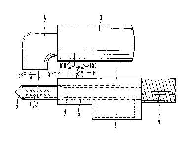
Fig. 1 shows a hair treatment device in which the
S switch according to the invention is
utilized;
Fig. 2 is an expanded view of an embodiment of
the switch;
Fig. 3 shows a view according to Fig. 1, but with
an enlarged portion of the switch and of
the contact springs 14' or 15' of the
contacts 14, 15 with which it interacts;
'
'
2a -
- .
::

~29~6~6
Flg. 4 i~ a dl~gram ehowlng ~he dierent operatlng ~t~t~s.
The known h~ir tr~t~ent devlco congists o~ ~ motor 1 locatod ln
a handle 11 which drives a ~leeve 6 which in turn holds ~ winding
m~ndrel 2 pro~ided with openlngs 7. The h~ndle ls connected to
negative-preasure aource vle ~ hoso 8~ The housing 9 la sn
integral part of the handle 11. It holdg the h~ir dryer 3 with
the outflow nozzle 4. The outflow of hot air is in the direction
of flow 5.
According to the invention the switch 10 is designed so as to be
able to carry out the four unctions initially mentlonea ln the
outline of the obJect o the lnvention. ~lo tn1s end lt can De
shifted up and down ~arrows lUU ln ~lg. lJ. lt can ~urtnermore
be tilted (arrows 1~1 in ~`ig. 1).
~he construction m~king this posslble lS seen ln ~ l9S. ~ ana ~.
As can be seen, the actu~l switch is constituted by the small
pl~te 10 at the two sides of which the switching cams are
integrated. These guiding ridges take their course in a fixedly
installed frame ~1. At the bottoms of the ridge~ or switching
cams the truncated cones 21 are integrally attached and are held
by the springs 22. The switch 10. can thus be shifted up and down
in this fr~me, whereby s~id fr~me is conet~ntly pushad by the
spring into its upper switching position and can be actuated on
the handle by an operator who pushes down on the lower actuating

129~616
~ur ~ce 24'o the ~wltch. Furth~rmc~re the 8wltch 10 (E~ml311 plote
20 with switching cam~ 12, 13, guidlng ridges 30 an~ trunc~ted
cones 21) within frame 31 c~n ~e tilt~d wlth its upper end from
the position shown in ~ig. 3 toward6 the left until its surfsce
32 i9 pushed against the lnner surfsce of fr~me 31, whlle the
surface ~3 of th~ guiding ridge 30 is in contact with the right
inner surface of the fr~me 31 while the switch 1~ in the starting
position shown.
The swltching c~m 1~ ia of the conflgur~tlon ~hown ln Flg. ~,
i.e. it is provided with ~ surface 12' extending st an ~ngle from
the bottom right to the top left. When the switch is depressed,
i.e. when a downw~rd movement is executed, this surf~ce c~uses
the switching cam 12 to act upon the contact spring lg' of the
irst cont~ct 14, thus closing this contact. This contact is
used to switch on the drive motor 1 of the winding mandrel ~.
The second switching cam 13 i~ also provided with a surf~ce 1~'
used for switching. This surface however extends at a par~llel
to the direction of the up and down displacement of the entire
switch 10 in the manner described ~bove, the surface 13'
therefore results to a switching contact with the contact spring
15' of the second contact 15 only when the switch 10 is tilted in
the manner described (direction 101 in Fig. 1~. The closing of
the contact 15 by this closing movement can be trQnslated by the
switch into turning the h~ir dryer 3 off so th~t the motor 1

12~
continue~ to run ~n~ mol~t alr ~ontlnue~ to ~e ~ucked through the
suction channel 7 ~nd the opening~ 7~ from the hair wound up on
the winding mandrel 2, however without ~ny ~imult~neous drying
action taking pl~ce.
As Fig. 2 shows, the switch 10 is provided with two depressions
~0, ~1 for the fingers to fucilit~te handling, so th~t an
operntor grasping the handle 11 and activating the switch 10 can
place his index finger either into depression 40 or 41, depending
on whether he wishes to push the switch up while tilting it at
tho s~me time, or whether he only wishes to tilt it in its upper
position.
The operating ~tste~ sre lndlcsted schematically in Fig. 4. The
upper one of the three figures shows thst the downward movement
without tilting merely c~uses the winding mandrel c~n be actuated
in the lower position while the dryer is switched on. In the
middle position the switch rem~ins in ~n upper position but is
tilted. The winding mandrel is not driven the hair dryer is
switched off. In the state of operation shown in the lowest of
the three drswings of Fig. 4 the hsir dryer is switched off, but
the motor 1 of the winding m~ndrel 2 is switched on.

Representative Drawing
A single figure which represents the drawing illustrating the invention.
Administrative Status

2024-08-01:As part of the Next Generation Patents (NGP) transition, the Canadian Patents Database (CPD) now contains a more detailed Event History, which replicates the Event Log of our new back-office solution.

Please note that "Inactive:" events refers to events no longer in use in our new back-office solution.

For a clearer understanding of the status of the application/patent presented on this page, the site Disclaimer , as well as the definitions for Patent , Event History , Maintenance Fee  and Payment History  should be consulted.

Event History

Description Date
Inactive: IPC from MCD 2006-03-11
Inactive: Adhoc Request Documented 1995-04-28
Time Limit for Reversal Expired 1994-10-28
Letter Sent 1994-04-28
Grant by Issuance 1992-04-28

Abandonment History

There is no abandonment history.

Owners on Record

Note: Records showing the ownership history in alphabetical order.

Current Owners on Record
ABC-ELEKTROGERATE VOLZ, GMBH & CO.
Past Owners on Record
HUBERT THEIMER
Past Owners that do not appear in the "Owners on Record" listing will appear in other documentation within the application.
Documents

To view selected files, please enter reCAPTCHA code :


To view images, click a link in the Document Description column. To download the documents, select one or more checkboxes in the first column and then click the "Download Selected in PDF format (Zip Archive)" or the "Download Selected as Single PDF" button.

List of published and non-published patent-specific documents on the CPD .

If you have any difficulty accessing content, you can call the Client Service Centre at 1-866-997-1936 or send them an e-mail at CIPO Client Service Centre.


Document
Description 
Date
(yyyy-mm-dd) 
Number of pages   Size of Image (KB) 
Abstract 1993-10-28 1 25
Cover Page 1993-10-28 1 15
Claims 1993-10-28 2 66
Drawings 1993-10-28 2 39
Representative Drawing 2003-03-19 1 10
Descriptions 1993-10-28 6 158