Sélection de la langue

Search

Sommaire du brevet 1299616 

Énoncé de désistement de responsabilité concernant l'information provenant de tiers

Une partie des informations de ce site Web a été fournie par des sources externes. Le gouvernement du Canada n'assume aucune responsabilité concernant la précision, l'actualité ou la fiabilité des informations fournies par les sources externes. Les utilisateurs qui désirent employer cette information devraient consulter directement la source des informations. Le contenu fourni par les sources externes n'est pas assujetti aux exigences sur les langues officielles, la protection des renseignements personnels et l'accessibilité.

Disponibilité de l'Abrégé et des Revendications

L'apparition de différences dans le texte et l'image des Revendications et de l'Abrégé dépend du moment auquel le document est publié. Les textes des Revendications et de l'Abrégé sont affichés :

  • lorsque la demande peut être examinée par le public;
  • lorsque le brevet est émis (délivrance).
(12) Brevet: (11) CA 1299616
(21) Numéro de la demande: 1299616
(54) Titre français: COMMUTATEUR POUR APPAREIL DE TRAITEMENT CAPILLAIRE
(54) Titre anglais: SWITCH FOR A HAIR TREATMENT DEVICE
Statut: Périmé et au-delà du délai pour l’annulation
Données bibliographiques
(51) Classification internationale des brevets (CIB):
  • H01H 25/06 (2006.01)
  • A45D 20/10 (2006.01)
  • A45D 20/12 (2006.01)
  • H01H 3/42 (2006.01)
  • H01H 9/06 (2006.01)
  • H01H 25/00 (2006.01)
(72) Inventeurs :
  • THEIMER, HUBERT (Allemagne)
(73) Titulaires :
  • ABC-ELEKTROGERATE VOLZ, GMBH & CO.
(71) Demandeurs :
(74) Agent: SWABEY OGILVY RENAULT
(74) Co-agent:
(45) Délivré: 1992-04-28
(22) Date de dépôt: 1988-10-11
Licence disponible: S.O.
Cédé au domaine public: S.O.
(25) Langue des documents déposés: Anglais

Traité de coopération en matière de brevets (PCT): Non

(30) Données de priorité de la demande:
Numéro de la demande Pays / territoire Date
P 37 36 101.5 (Allemagne) 1987-10-24

Abrégés

Abrégé anglais


ABSTRACT OF THE INVENTION
What is described is a switch for a hair treatment device,
consisting of a winding mandrel (2) driven rotationally by a
motor (1) and of a hair dryer (3) whose outflow nozzle (4) is
directed perpendicularly upon the axis of the winding mandrel (2)
and tangentially to its circumference. A switch (10) is provided
to switch the hair dryer of the drive motor (1) of the winding
mandrel on and off, whereby the switch (10) can be shifted from
an upper position to a lower position towards the handle on a
housing element (11) made in form of a handle for an operator.
The switch (10) can furthermore be tilted out of the shifting
plane and is provided with two switching cams (12, 13), whereby
one switching cam (12) actuates a first contact (14) through
which the motor (1) of the winding mandrel (2) is switched on
independently of the tilting position of the switch (10) when
said switch is shifted into the lower position, closer to the
handle (10). The second switching cam (13) is of such
configuration as to cause the hair dryer (3) to be switched off
by activating a second contact (15) when tilting takes place.
(Fig. 2)

Revendications

Note : Les revendications sont présentées dans la langue officielle dans laquelle elles ont été soumises.


The embodiments of the invention in which
an exclusive property or privilege is claimed are
defined as follows:
1. A switch for a hair treatment device,
consisting of a winding mandrel driven by a motor
and by a hair dryer whose outflow nozzle is directed
upon the winding mandrel perpendicularly to the axis
of said winding mandrel and tangentially to its
circumference, with a switch to switch on and off
the hair dryer of the drive motor of the winding
mandrel, whereby the switch is installed on the
housing part made in form of a handle for the
operator in such manner that it can be moved from an
upper position into a lower position in the
direction of the handle, characterized in that the
switch can furthermore be tilted from the shifting
plane and is provided with two switching cams,
whereby one switching cam actuates a first contact
through which the motor of the winding mandrel is
activated when it is shifted into the lower
position, closer to the handle, whereby this action
takes place independently of any tilting position of
the switch, and in that the second switching cam is
shaped so that it actuates a second contact through
which the hair dryer is switched off when the switch
is tilted.
2. A switch as defined in claim 1,
characterized in that the first switching cam
mentioned is provided with a surface extending at an
angle downward in such manner that a downward
movement causes the movable contact spring of the
first contact to be pressed into closing position.

3. A switch as defined in claim 1,
characterized in that the second switching cam is
provided with a pressure surface extending at a
parallel to the direction of the up and down
movement, so that an action of the switch upon the
movable contact spring of the second contact occurs
only when the switch is tilted.
4. A switch as defined in claim 1,
characterized in that the switch is constituted by a
small plate at the two sides of which the switching
cams are integrated in casting.
5. A switch as defined in claim 4,
characterized in that truncated cones are located on
the underside of the small plate or the integrated
switching cams and serve to receive the switch in a
receiving part so as to cause tilting, said part
consisting preferably of a spring.
6. A switch as defined in claim 1,
characterized in that it is constituted by an
element capable of being shifted up and down, at
either side of which guiding ridges each of which
runs in a frame are provided, whereby the limit
surfaces of the guiding ridges make it possible for
limited tilting within the frame to take place.
7. A switch as defined in claim 1,
characterized in that two depressions for the
placement of fingers are formed integrally into the
actuating surface.

Description

Note : Les descriptions sont présentées dans la langue officielle dans laquelle elles ont été soumises.

~z~
0114 ~3~ ~cto~er ~3, 19~7 ~/m~
Title: Switch ~or a H~ir Tre~tment De~ice
~scription
The instant invention relates to a switch for a hair tre~tment
de~ice according to the introductory clau-~e of claim 1.
A h~ir treatment device of thie type is known from the EP patent
0 052 325.
Basing itself on same, it i6 the ob~eck of the instant invention
to design the switch so that four functions bPcome possible,
l.e.:
- Winding mandrel at rest, hair dryer on;
- Winding mandrel in operation, hair dryer on;
- Winding mandrel at rest, hair dryer off;
- Winding mandrel in operation, hair dryer off.
The possibility of switching the halr dryer and the winding
mandrel on and off independently of each other is ko be created~

~2~i16
This leads to the four combination possibilities
mentioned abo~e. In that case it is in particular
possible to keep the winding mandrel running without
switching on the hair dryer, that is to say without
drying action and therefore without heating, for
instance in order to treat the hair without drying,
merely to smooth it and/or to give it shape. This
may be desirable for instance to cool the hair since
in the known device the air is in any case sucked
through the openings in the winding mandrel and
through the hair wound up on it.
In accordance with a particular embodiment
of the invention there is provided a switch for a
hair treatment device, consisting of a winding
mandrel driven by a motor and by a hair dryer whose
outflow nozzle is directed upon the winding mandrel
perpendicularly to the axis of said winding mandrel
and tangentially to its circumference, with a switch
to switch on and off the hair dryer of the drive
motor of the winding mandrel, whereby the switch is
installed on the housing part made in form of a
handle for the operator in such manner that it can
be moved from an upper position into a lower
position in the direction of the handle,
characterized in that the switch can furthermore be
tilted from the shifting plane and is provided with
two switching cams, whereby one switching cam
actuates a first contact through which the motor of
the winding mandrel is activated when it is shifted
into the lower position, closer to the handle,
whereby this action takes place independently of any
tilting position of the switch, and in that the
second switching cam is shaped so that it actuates a
second contact through which the hair dryer is
35 switched off when the switch is tilted.
.
. ~ .
:` ' ' .

An embodiment of the invention and of its
advantageous further embodiment are described
through the enclosed drawings in which~
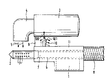
Fig. 1 shows a hair treatment device in which the
S switch according to the invention is
utilized;
Fig. 2 is an expanded view of an embodiment of
the switch;
Fig. 3 shows a view according to Fig. 1, but with
an enlarged portion of the switch and of
the contact springs 14' or 15' of the
contacts 14, 15 with which it interacts;
'
'
2a -
- .
::

~29~6~6
Flg. 4 i~ a dl~gram ehowlng ~he dierent operatlng ~t~t~s.
The known h~ir tr~t~ent devlco congists o~ ~ motor 1 locatod ln
a handle 11 which drives a ~leeve 6 which in turn holds ~ winding
m~ndrel 2 pro~ided with openlngs 7. The h~ndle ls connected to
negative-preasure aource vle ~ hoso 8~ The housing 9 la sn
integral part of the handle 11. It holdg the h~ir dryer 3 with
the outflow nozzle 4. The outflow of hot air is in the direction
of flow 5.
According to the invention the switch 10 is designed so as to be
able to carry out the four unctions initially mentlonea ln the
outline of the obJect o the lnvention. ~lo tn1s end lt can De
shifted up and down ~arrows lUU ln ~lg. lJ. lt can ~urtnermore
be tilted (arrows 1~1 in ~`ig. 1).
~he construction m~king this posslble lS seen ln ~ l9S. ~ ana ~.
As can be seen, the actu~l switch is constituted by the small
pl~te 10 at the two sides of which the switching cams are
integrated. These guiding ridges take their course in a fixedly
installed frame ~1. At the bottoms of the ridge~ or switching
cams the truncated cones 21 are integrally attached and are held
by the springs 22. The switch 10. can thus be shifted up and down
in this fr~me, whereby s~id fr~me is conet~ntly pushad by the
spring into its upper switching position and can be actuated on
the handle by an operator who pushes down on the lower actuating

129~616
~ur ~ce 24'o the ~wltch. Furth~rmc~re the 8wltch 10 (E~ml311 plote
20 with switching cam~ 12, 13, guidlng ridges 30 an~ trunc~ted
cones 21) within frame 31 c~n ~e tilt~d wlth its upper end from
the position shown in ~ig. 3 toward6 the left until its surfsce
32 i9 pushed against the lnner surfsce of fr~me 31, whlle the
surface ~3 of th~ guiding ridge 30 is in contact with the right
inner surface of the fr~me 31 while the switch 1~ in the starting
position shown.
The swltching c~m 1~ ia of the conflgur~tlon ~hown ln Flg. ~,
i.e. it is provided with ~ surface 12' extending st an ~ngle from
the bottom right to the top left. When the switch is depressed,
i.e. when a downw~rd movement is executed, this surf~ce c~uses
the switching cam 12 to act upon the contact spring lg' of the
irst cont~ct 14, thus closing this contact. This contact is
used to switch on the drive motor 1 of the winding mandrel ~.
The second switching cam 13 i~ also provided with a surf~ce 1~'
used for switching. This surface however extends at a par~llel
to the direction of the up and down displacement of the entire
switch 10 in the manner described ~bove, the surface 13'
therefore results to a switching contact with the contact spring
15' of the second contact 15 only when the switch 10 is tilted in
the manner described (direction 101 in Fig. 1~. The closing of
the contact 15 by this closing movement can be trQnslated by the
switch into turning the h~ir dryer 3 off so th~t the motor 1

12~
continue~ to run ~n~ mol~t alr ~ontlnue~ to ~e ~ucked through the
suction channel 7 ~nd the opening~ 7~ from the hair wound up on
the winding mandrel 2, however without ~ny ~imult~neous drying
action taking pl~ce.
As Fig. 2 shows, the switch 10 is provided with two depressions
~0, ~1 for the fingers to fucilit~te handling, so th~t an
operntor grasping the handle 11 and activating the switch 10 can
place his index finger either into depression 40 or 41, depending
on whether he wishes to push the switch up while tilting it at
tho s~me time, or whether he only wishes to tilt it in its upper
position.
The operating ~tste~ sre lndlcsted schematically in Fig. 4. The
upper one of the three figures shows thst the downward movement
without tilting merely c~uses the winding mandrel c~n be actuated
in the lower position while the dryer is switched on. In the
middle position the switch rem~ins in ~n upper position but is
tilted. The winding mandrel is not driven the hair dryer is
switched off. In the state of operation shown in the lowest of
the three drswings of Fig. 4 the hsir dryer is switched off, but
the motor 1 of the winding m~ndrel 2 is switched on.

Dessin représentatif
Une figure unique qui représente un dessin illustrant l'invention.
États administratifs

2024-08-01 : Dans le cadre de la transition vers les Brevets de nouvelle génération (BNG), la base de données sur les brevets canadiens (BDBC) contient désormais un Historique d'événement plus détaillé, qui reproduit le Journal des événements de notre nouvelle solution interne.

Veuillez noter que les événements débutant par « Inactive : » se réfèrent à des événements qui ne sont plus utilisés dans notre nouvelle solution interne.

Pour une meilleure compréhension de l'état de la demande ou brevet qui figure sur cette page, la rubrique Mise en garde , et les descriptions de Brevet , Historique d'événement , Taxes périodiques et Historique des paiements devraient être consultées.

Historique d'événement

Description Date
Inactive : CIB de MCD 2006-03-11
Inactive : Demande ad hoc documentée 1995-04-28
Le délai pour l'annulation est expiré 1994-10-28
Lettre envoyée 1994-04-28
Accordé par délivrance 1992-04-28

Historique d'abandonnement

Il n'y a pas d'historique d'abandonnement

Titulaires au dossier

Les titulaires actuels et antérieures au dossier sont affichés en ordre alphabétique.

Titulaires actuels au dossier
ABC-ELEKTROGERATE VOLZ, GMBH & CO.
Titulaires antérieures au dossier
HUBERT THEIMER
Les propriétaires antérieurs qui ne figurent pas dans la liste des « Propriétaires au dossier » apparaîtront dans d'autres documents au dossier.
Documents

Pour visionner les fichiers sélectionnés, entrer le code reCAPTCHA :


Pour visualiser une image, cliquer sur un lien dans la colonne description du document. Pour télécharger l'image (les images), cliquer l'une ou plusieurs cases à cocher dans la première colonne et ensuite cliquer sur le bouton "Télécharger sélection en format PDF (archive Zip)" ou le bouton "Télécharger sélection (en un fichier PDF fusionné)".

Liste des documents de brevet publiés et non publiés sur la BDBC .

Si vous avez des difficultés à accéder au contenu, veuillez communiquer avec le Centre de services à la clientèle au 1-866-997-1936, ou envoyer un courriel au Centre de service à la clientèle de l'OPIC.


Description du
Document 
Date
(aaaa-mm-jj) 
Nombre de pages   Taille de l'image (Ko) 
Abrégé 1993-10-28 1 25
Page couverture 1993-10-28 1 15
Revendications 1993-10-28 2 66
Dessins 1993-10-28 2 39
Dessins représentatifs 2003-03-19 1 10
Description 1993-10-28 6 158