Language selection

Search

Patent 1299620 Summary

Third-party information liability

Some of the information on this Web page has been provided by external sources. The Government of Canada is not responsible for the accuracy, reliability or currency of the information supplied by external sources. Users wishing to rely upon this information should consult directly with the source of the information. Content provided by external sources is not subject to official languages, privacy and accessibility requirements.

Claims and Abstract availability

Any discrepancies in the text and image of the Claims and Abstract are due to differing posting times. Text of the Claims and Abstract are posted:

  • At the time the application is open to public inspection;
  • At the time of issue of the patent (grant).
(12) Patent: (11) CA 1299620
(21) Application Number: 583157
(54) English Title: THERMAL PROTECTING BLANKET FOR A WELL HEAD CONTROL DEVICE
(54) French Title: MATELAS DE PROTECTION THERMIQUE POUR APPAREIL DE REGULATION DE LA PRESSION EN TETE DE PUITS
Status: Expired
Bibliographic Data
Abstracts

English Abstract


4683-002
ROGERS, BERESKIN & PARR CANADA

TITLE: THERMAL PROTECTING BLANKET FOR
A WELL HEAD CONTROL DEVICE

INVENTORS: ROBERT A. ANDERSON


ABSTRACT


A thermal protecting blanket for a well head
control device such as a blow out preventor. The blanket, is
specially adapted for use in hazardous environments.It
includes a flexible cover custom fitted to the shape of the
well head control device, an electrical heating element
disposed on the inside of the flexible cover, and which is
detachable, and the cover having a closable opening so that,
it may be closed to insulate the well head control device,
and opened to permit access to the device during servicing.
The electrical heating element is detachable, and self
regulating. External connections for the well head control
device pass through openings in the flexible cover, and the
openings are held tight against the external connections by
a drawstring. The fabric cover is made of ail resistant,
water resistant and fire resistant material.


Claims

Note: Claims are shown in the official language in which they were submitted.


-8-
THE EMBODIMENTS OF THE INVENTION IN WHICH AN EXCLUSIVE
PROPERTY OR PRIVILEGE IS CLAIMED ARE DEFINED AS FOLLOWS:
1. A thermal protecting apparatus for a well head
control device comprising:
a flexible outer cover fitted to the shape of the
well head control device;
an electrical heating element disposed on the inside
of the flexible outer cover;
the flexible outer cover being adjustable between a
first position in which the well head control device is
insulated from the environment and a second position in
which the well head control device is exposed to and
accessible from the environment;
means for fastening the flexible outer cover in the
first position; and
an electrical power source connected to the
electrical heating element.

2. The thermal protecting apparatus of claim 1 in which
the well head control device includes rubber seals for
sealing the well head control device, and in which the
electrical heating element is self regulating at a range of
temperatures in which the rubber seals function.

3. The thermal protecting apparatus of claim 1 in which
the flexible outer cover is made from water resistant, fire
resistant and oil resistant material.

4. The thermal protecting apparatus of claim 1, 2 or 3
in which the flexible outer cover is made from water
resistant, fire resistant and oil resistant material which
is functional between -40° and +100°C.

5. The thermal protecting apparatus of claims 1, 2 or
3 in which the electrical heating element is detachably
attached to the flexible outer cover.


-9-
6. The thermal protecting apparatus of claims 1, 2 or
3 in which the flexible outer cover is a substantially
rectangular pad having a plurality of openings for the well
head control device external connections, and having, for
each opening, means for tightening and substantially
sealing the flexible outer cover against the external
connections, the substantially rectangular pad being
fastened in the second position by fastening means at its
longitudinal ends.

7. The thermal protecting apparatus of claims 1, 2 or
3 in which the flexible outer cover is custom fit for a
particular well head control device, having a plurality of
openings for the well head control device external
connections, and having, for each opening, means for
tightening and substantially sealing the flexible outer
cover against the external connections.

8. The thermal protecting apparatus of claims 1, 2 or
3 in which the electrical heating element is disposed
between inner and outer fabric pads, and the outer fabric
pad is detachably attached to the flexible outer cover.

9. The thermal protecting apparatus of claims 1, 2 or
3 in which the electrical heating element is disposed
between inner and outer fabric pads, and the outer fabric
pad is detachably attached to the flexible outer cover and
further including conducting material lining the inside of
the inner fabric pad facing the well head control device.

10. A thermal protecting apparatus for a well head
control device, having external connections, the thermal
protecting apparatus comprising:

- 10 -

a flexible outer cover having a plurality of
openings fitted to the shape of the well head control
device external connections;
means for tightening and substantially sealing the
flexible outer cover against the well head control device
external connections;
an outer pad detachably attached to the inside of
the flexible outer cover;
an inner pad attached to the outer pad;
a self regulating electrical heating element
disposed between the inner and outer pads;
the flexible outer cover being adjustable between a
first position in which the well head control device is
insulated from the environment and a second position in
which the well head control device is exposed to and
accessible from the environment;
means for fastening the flexible outer cover in the
first position; and
an electrical power source connected to the self
regulated electrical heating element.

11. A thermal protecting apparatus for a blowout
preventer, having external connections, the thermal
protecting apparatus comprising:
a flexible cover having a plurality of openings
fitted to the shape of the blowout preventor external
connections;
an outer pad detachably attached to the inside of
the flexible cover;
an inner pad having first and second sides, the
first side being attached to the outer pad;
a self regulating electrical heating element
disposed between the inner and outer pads;
the flexible cover being adjustable between a first
position in which the blowout preventor is insulated from
the environment and a second position in which the blowout

-11-
preventor is exposed to and accessible from the
environment;
a conductive lining attached to the second side of
the inner pad and disposed on the inside of the electrical
heating element such that the conductive lining is disposed
between the electrical heating element and the blowout
preventor when the flexible cover is in the first
position.;
means for fastening the flexible cover in the first
position; and
an electrical power source connected to the self
regulated electrical heating element.

12. A thermal protecting apparatus for a blow out
preventor, having external connections, comprising:
a flexible cover having a plurality of openings
fitted to the shape of the blow out preventor external
connections;
an electrical heating element disposed on the inside
of the flexible cover;
the flexible cover being adjustable between a first
position in which the blowout preventor is insulated from
the environment and a second position in which the blow out
preventor is exposed to and accessible from the
environment;
means for fastening the flexible cover in the first
position;
an electrical power source connected to the
electrical heating element; and
in which the flexible cover comprises an outer
layer, a middle layer made of flexible insulating material
and an inner layer made of fire, oil and water resistant
material.

13. The thermal protecting apparatus of claim 12
further including a conductive lining disposed on the

- 12 -

inside of the electrical heating element such that the
conductive lining is disposed between the electrical
heating element and the blowout preventor when the flexible
cover is in the first position.

14. The thermal protecting apparatus of claim 13 in
which the electrical power source is connected to the
electrical heating element by explosion proof connectors.

Description

Note: Descriptions are shown in the official language in which they were submitted.


~L299~2~
-2-
This invention relates -to an apparatus for -the
thermal protectlon of well head control devices such as blow
out preventors (BOPs).
Well head control devices often operate in
extremely cold environments where -temperatures reach below
-40C. A11 of these well head control devices, such as
BOPs, operate under high pressure and contain rubber parts
which provide a sealing function for the well contents.
Extreme cold can affect the sealing function of the rubber
parts and this can lead to failure of the seal, resulting in
a dangerous environment. In addition, normal cold weather
operation of the BOP can lead to a build-up of frost or rime
in the bore of the BOP which impairs its safety.
In the past, methods of heating BOPs have
involved: heating water in a boiler, and transferring the
heat from the heated water to the BOP through a heat
exchanger; or blowing air through a heated glycol filled
radiator onto the surface of the BOP. These methods were
inefficient due to a loss of heat to the environment.
Another method utilized a rigid box or container
surrounding the BOP. While this improved heat retention,
access to the BOP was restricted.
The present invention helps avoid the difficulties
of the prior art and provides, in one aspect, a thermal
protecting apparatus for a well head control device
comprising:


`-- 1299620


a flexible cover fitted to the shape of the well
head control devlcei
an electrical heating element disposed on the
inside of the flexible cover;
the cover being adjustable between a first
position in which the well head control device is insulated
from the environment and a second position in which the well
head control device is exposed to and accessible from the
environment;
means for fastening the cover in the first
position; and
an electrical power source connected to the
electrical heating element.
Further summary of the invention may be found in
the claims forming a part of this patent.
In drawings which illustrate embodiments of the
invention, by way of example:
Figure 1 is a perspective of a heating cover
according to the invention for a ram type BOP heater in
which the heating cover is in open posltion;
Figure 2 is a perspective of a heating cover
according to the invention for an annular BOP heater in
which the heatlng cover 1S in open position;
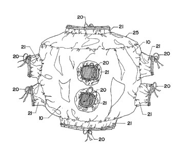
Flgure 3 lS a front view of a heating cover
according to the lnventlon for a ram type BOP; and
Figure 4 is a rear view of a heating cover
according to the invention for a ram type BOP.


- . ~ . . . .

;. , . ~ . ,
:. - : . ,

~zo
, --4--
~ l~wo ~yl~es of ~OI are widely used for well llecl-J
pressure conf:ro1. The embodiînen',s of ~,he inverll,iorl
described here are cus~,om tailored to ~,he ~onfigura',iorl of
the ram type and annul~r ~,ype of g~P. O~,her corlfigl1r-~,ion~
of well head con~:rol devices may be fi~,l,ed wil.h ~,he heal,incJ
cover of t,he invent,ion wi~,h appropria~,e modificat,ions to ~,he
shape of t.he heat,ing cover.
Figure l shows a hea~,ing r-over cust,om con~oured
for t.he ram ~.ype BOP. ~igure 2 shows a heat.ing cover custorn
cont.oured for the annular ~ pe soP. In bo'.h designs, ~.he
cover is made of an out.er shell 10, inner shell 12 and a
layer of insulat,ion 14 sandwiched be~,ween t:he inner shell 10
and ou~,er shell 12. rlle ou~,er shel,l 10 is preferably rnade
of a fire resist.an~,, oil resisl,an~,, and wat.er rcsistarl~
flexible fabric funct,ional from -40C ~.o ]00C SUCIl as
Arct.ic Hyprene* available from Norseman Shel~,ers. Ihe inner
shell 12 is made of woven glas fibre. 7lle in~ul;l'iorl ]4 ~i
preferably a layer of solimide foam or ot.her fire resistan~
mat.erial. The layers of fabric and insula',ion are showll In
the area generally loca~.ed c~: 16, and are sewn l:ogetller in
known fashion about. t,he peri~et.er of t,he cover.
The flexibilit.y of ~.lle r-over perrni~s i~ o be
wrapped around t.he BOP. Drawst.rings 20 on sleeve 21 are
used t.o sea~ ':he cover agains~. ~.he ex~,ernal conrlecl,i ons and
well head connect.ion of -.ne BOP by l.iglll,erling of ',he
drawstrings 20. Out.let,s 18 are for t,he hydraulic
connect.ions t,o t.he ram l.ype BOP. In Figure 2, openings 23
receive t.he ext,ernal connecl,ions of ~ e annular Iyl~e l30P.


*Trademark

~;~9~;~0


Overlapping fl.aps 22 and 24 have complementary VELCRO m
stri.ps (VELCRO is a trade mark of Velcro Corpora~,i.on) on
their inner and outer facing surfaces respect,ively. The
flaps 22 and 24 and straps 26 wi,t,h complementary buckles 28
fasten the cover about t,he BOP. Straps 26 are preferably
made of nylon.
The cover i.s substantially rectangular and is
cust,om fit for the particular BOP and is provided wi.th
enclosing ends 25 so tha~, when the cover is i,n its closed
position, i.nsulating the BOP, it, i,s substantiall.y
cylindrical. The flaps 22 and 24 are at the longitudinal
ends of the cover.
Pouch 30, shown partially cut-away in figures 1
and 2, houses explosion proof connectors 32, which are
readily commercially available. Connectors 32 connect 110v
power cords 34 to the self regulating heating cable 36.
Self regulating heating cable 36 is rated at 110v x 10-20
watts/Ft, approved for hazardous environment (Class I, Div
II Groups (ànd D) and may also be readiJ.y commercially
obtained. Sel.f regulating heating cables 36 terminate in
explosion proof termi.nat,ors 38, also readily commercially
available. The self regulating heating cables 36 are
preferably selected to ma.intain the BOP or o-ther well head
control devlce within a range of temperatures speci.fi.ed by
the manufacturers of the seals of the BOP, or other well
head control~devi.ce, to be satisfactory for the performance
of the rubber seals. For example, typical rubber seals
operate in a -temperature range of -7C to +60C.


. . . ' . . ' ~ ~ :
. .
, . ' . ~ . . ,' ' :

.
,: , : . .

~2~9~;20

Self regulatlng heating cables 36 are fastened by
s-tltching between the detachable pads 42 and internal pads
46 are fastened to the inner shell 12 by snaps 44. Separated
pads 42, as shown for the ram type BOP in Figure l, may be
used to bridge openings for external connections to the BOP.
The pads 42 are preferably made of fire resistant, oil
resistant, and water resistant material, such as woven glas
fibre. The internal pads 46 are made of similar material
and may be lined with metal wool to improve heat
distribution.
The wire size in the self regulating heating
cables 36 should be adjusted to meet temperature rating
limitations set by the Canadian Standards Association
according to the well bore fluids being used.
One or more RTDs (not shown) may be inserted into
the pads 42 or 46 in contact with outside terminals for
checking the inside temperature of the cover, without
removal of the cover. Straps 48 are preferably strain relief
detention straps, which are readily commercially available.
If desired, the self regulating heating cables 36
may be plugged into a breaker box (not shown). The breaker
box may be wired to kick out if the ground connection is
broken.
In use, the cover may be readily applied a~d
fitted to the BOP. Straps 26, flaps 22 and 24 and
drawstrlngs 20 are secured to provide a substantially
airtight cover for the BOP. In the case of the annular type
BOP, the openings 23 fit snugly against its external


`''''~` '


- ' "

129g~D

connections. The temperature of the BOP 1s regulated by the
self regula-tlng heating cable 36. Ready access to the BOP

for servicing is provided by the stxaps 26 and VELCROtm
flaps 22 and 24.
Clearly, other methods of fastening the cover

about the BOP may be used. For example, instead of VELCRO
flaps and buckles, rings and hooks, zips, buttons or straps
only could be used. Overlapping flaps are desirable to
improve the insulating capacity of the cover. Elasticized
material at the edge of each opening may be used instead of
drawstrings for fastening the opening of the cover about
external connections to the well head control device.
Other alternative but e~uivalent devices may be
constructed by persons skilled in the art, but these are
intended to be covered by the claims which follow.


Representative Drawing
A single figure which represents the drawing illustrating the invention.
Administrative Status

For a clearer understanding of the status of the application/patent presented on this page, the site Disclaimer , as well as the definitions for Patent , Administrative Status , Maintenance Fee  and Payment History  should be consulted.

Administrative Status

Title Date
Forecasted Issue Date 1992-04-28
(22) Filed 1988-11-15
(45) Issued 1992-04-28
Expired 2009-04-28

Abandonment History

There is no abandonment history.

Payment History

Fee Type Anniversary Year Due Date Amount Paid Paid Date
Application Fee $0.00 1988-11-15
Maintenance Fee - Patent - Old Act 2 1994-04-28 $50.00 1994-04-06
Maintenance Fee - Patent - Old Act 3 1995-04-28 $250.00 1995-09-14
Maintenance Fee - Patent - Old Act 4 1996-04-29 $50.00 1996-04-04
Maintenance Fee - Patent - Old Act 5 1997-04-28 $75.00 1997-03-25
Maintenance Fee - Patent - Old Act 6 1998-04-28 $75.00 1998-04-24
Registration of a document - section 124 $100.00 1998-06-01
Maintenance Fee - Patent - Old Act 7 1999-04-28 $150.00 1999-03-09
Maintenance Fee - Patent - Old Act 8 2000-04-28 $150.00 2000-02-07
Maintenance Fee - Patent - Old Act 9 2001-04-30 $75.00 2001-01-17
Maintenance Fee - Patent - Old Act 10 2002-04-29 $200.00 2002-01-29
Maintenance Fee - Patent - Old Act 11 2003-04-28 $200.00 2003-02-14
Maintenance Fee - Patent - Old Act 12 2004-04-28 $200.00 2003-12-02
Back Payment of Fees $125.00 2005-04-26
Maintenance Fee - Patent - Old Act 13 2005-04-28 $125.00 2005-04-26
Back Payment of Fees $125.00 2006-03-03
Maintenance Fee - Patent - Old Act 14 2006-04-28 $125.00 2006-03-03
Back Payment of Fees $225.00 2007-04-03
Maintenance Fee - Patent - Old Act 15 2007-04-30 $225.00 2007-04-03
Maintenance Fee - Patent - Old Act 16 2008-04-28 $450.00 2008-02-26
Owners on Record

Note: Records showing the ownership history in alphabetical order.

Current Owners on Record
361428 ALBERTA LTD
Past Owners on Record
ANDERSON, ROBERT A.
Past Owners that do not appear in the "Owners on Record" listing will appear in other documentation within the application.
Documents

To view selected files, please enter reCAPTCHA code :


To view images, click a link in the Document Description column. To download the documents, select one or more checkboxes in the first column and then click the "Download Selected in PDF format (Zip Archive)" or the "Download Selected as Single PDF" button.

List of published and non-published patent-specific documents on the CPD .

If you have any difficulty accessing content, you can call the Client Service Centre at 1-866-997-1936 or send them an e-mail at CIPO Client Service Centre.


Document
Description 
Date
(yyyy-mm-dd) 
Number of pages   Size of Image (KB) 
Description 1993-10-28 6 199
Drawings 1993-10-28 4 158
Claims 1993-10-28 5 176
Abstract 1993-10-28 1 29
Cover Page 1993-10-28 1 13
Representative Drawing 2002-01-28 1 18
Fees 2003-02-14 1 28
Fees 2003-12-02 2 44
Fees 2000-02-07 1 27
Fees 2008-02-26 1 35
Fees 2002-01-29 1 29
Fees 2001-01-17 1 27
Fees 1998-04-24 1 39
Correspondence 1998-06-18 1 1
Fees 1999-03-09 1 29
Correspondence 1998-06-09 2 46
Fees 2005-04-26 1 26
Fees 2006-03-01 1 30
Fees 2007-04-03 1 31
Fees 1997-03-25 1 36
Fees 1996-04-04 1 37
Fees 1995-09-14 1 44
Fees 1994-04-06 1 36