Note: Descriptions are shown in the official language in which they were submitted.
o~
NE- 160
- 1 -
TITLEi OF THE INVENTION
2 "Concentrator System Capable of Completing Emergency Calls
3 Under Congested Traffic"
4 BACKGROIJND OF THE INVENTION
The present invention relates to a concentrator system for
6 connecting geographically scattered subscriber terminals to the public
7 switched telecommunication network through limited channel resources.
8 More specifically, the invention relates to such a concentrator system in
9 which emergency calls to police departments or fire stations are
0 completed through a specially reserved channel.
11 Radio concentrator systems have been developed as an economic
12 means for connecting remotely located subscriber terminals, such as
13 telephones and data terminals, to an access point of the public switched
14 telephone network through demand-assigned time division access
channels. The system comprises a central station located relatively close
16 to the access point of the network and a plurality of remote stations to
17 which the subscriber terminals are connected by groups. Because of the
18 limited number of demand-assigned channels, congestion tends to occur
19 at peak traffic loads. With prior art radio concentrator systems, an
2 0 emergency call from ordinary subscribers is treated as an ordinary call
21 and routed through one of the demand-assigned channels if it is
2 2 available. The prior art system is provided with one or more channels
2 3 which are specially preassigned to special subscribers to allow them to
24 complete an emergency call under congested traffic. However, an
2 5 emergency call from ordinary subscribers must be abandoned when it
2 6 encounters a condition indicating that all channels are busy.
2 7 ~UMMARY OF THE INVENTION
28 It is therefore an object of the present invention to provide a
2 9 concentrator system which allows an emergency call frorn any sllbscriber
NE- 160
-2
to be completed when the demand-assigned channels are congested with
2 traffic.
3 In a concentrator system of the present invention, demand-assigned
4 speech or data chanrlels are constantly monitored by the central station toS detect when they are congested. When an emergency call is received from
6 a subscriber terminal, typically in the form of a "hook flash", or
7 momentary depression of the switchhook, a dial -tone is sent to the
8 terrninal if the emergency call occurs simultaneously with the detection of9 the channel conges-tion. On hearing the dial tone, the subscriber dials an
emergency destination address, which is received by a remote station and
1 1 compared with a list of predetermined addresses and verified if it matches
12 one of the predetermined addresses. The dialled information is sent from
13 that remote station to the central station, where it is relayed to an access
14 point of the switched telecommunication network. An emergency channel
is then established between the subscriber terminal and the network for
l 6 routing the emergency call.
17 The emergency channel may be permanently provided in the
l 8 transmission link between the central station and remote stations and
19 demand-assigned by the central station to a remote station in response to
2 0 an emergency channel assignment request therefrom or first selected by
2 l the remote station requesting an emergency call and access is granted to it22 if no collision occurs between competing emergency call attempts.
2 3 Alternatively, no emergency channel is provided in the system and one of
2 4 the data channels is cleared when an emergency call is detected
simultaneously with the occurrence of a condition indicating all da-ta
2 6 channels are busy. The cleared channel is used as an emergency channel
2 7 to complete the emergency call.
2 8 In a more specific aspect, the concentrator system of the present
2 9 invention is made up of a central station and a plurality of remote stations
NE- 160
- 3 -
interconnected by a two-way transmission link. The central station
2 comprises a plurality of subscriber line interface circuits associated in a
3 one-to-one correspondence to the subscriber terminals and connected to
4 the switched telecommunication network, and a controller cooperating
S with the subscriber line interface circuits for selecting a data channel in
6 the transmission link in response to a channel assignment request either
7 from the network and the remote stations and generating a data channel
8 selection signal identifying the selected data channel. The controller
9 detects when all of the data channels are busy and generates an all-busy
10 signal. In the central station, multiplexer/demultiplexer circuitry
1 1 connects the subscriber line interface circuits to the selected data channels
12 in response to the data channel selection signal, connects one of the
l 3 subscriber line interface circuits from which an emergency call is requestedl 4 to the transmission link, connects the data channel selection signal and thel 5 all-busy signal to the link for transmission to the remote stations, and
l 6 applies the channel assignment request, which has been received from the
17 remote stations through the link, to the central station controller. The
18 multiplexer/demultiplexer further detects an emergency destination
19 address transmitted from the remote stations on the link. ~ dialling
20 circuit is provided in the central station for signalling the detected
21 emergency destination address to the network. Each of the remote
2 2 stations comprises a plurality of remote subscriber line interface circuits
23 connected respectively to the subscriber terminals and a plurality of
2 4 registers associated respectively with the subscriber terminals for
25 transmitting a dial tone to the emergency call requesting subscriber
2 6 terminal and receiving the emergency destination address therefrom. A
27 remote controller in each remote station cooperates with the rernote
28 subscriber line interface circuits to generate the channel assignment
29 request in response to an outgoing call request from the subseriber
NE- 160
- 4 -
terminals ~nd detect a simultaneous occurrence of the all-busy signal
2 from the central station and an emergency call from the emergency
3 requesting subscriber terminal. The remote controller causes one of the
4 registers to send dial tone to the emergency call requesting subscriber
S terminal in response to the detection of the simultaneous occurrence, and
6 verifies the emergency call by detecting a coincidence between the
7 received destination address with a list of predetermined emergency
~ destination addresses. Remote station multiplexer/demultiplexer
9 circuitry establishes connection of the remote subscriber line interface
circuits to the selected data channels in response to the data channel
11 selection signal, connection of one of the remote subscriber line interface12 circuits which is associated with the emergency call requesting subscriber
13 terminal to the transmission link, connection of the channel assignment
14 request and the emergency destination address of the verified emergency
call to the transmission link, and provides connection of the data channel
16 selection signal and the all-busy signal, which have been transmitted from
17 the central station on the link, to the remote controller.
l 8 - BRIEF DESCRIPTION OF THE DRAWINGS
19 The present invention will be described in further detail with
2 0 reference to the accompanying drawings, in which:
21 Fig. l is a block diagram of a radio concentrator system embodying
2 2 the present invention;
2 3 Fig. 2 is a block diagram of the central station of Fig. 1;
2 4 Fig. 3 is a block diagram of each of the remote stations of Fig. 1;
2s Figs. 4A and 4B are flowcharts describing the operation of the
26 concentrator system according to a first embodiment of the present
2 7 invention, and Fig. a~c is a data flow diagram useful for understanding
2 8 the operation of the first embodiment;
29 Figs. 5A and 5B are flowcharts describing the operation of the
IL2~ )6
NE- 160
- 5 -
concentrator system ac~ording to a second embodiment of the present
2 invention, and ~ig. 5C is a data flow diagram useful for understancling
3 the operation of the second embodiment;
4 Figs. 6A and 6B are flowcharts describing lhe operation of the
concentrator s~stem according to a second embodiment of the present
6 invention, and Fig. 6C is a data flow diagram useful for understanding
7 the operation of the third embodiment;
8 Fig. 7 shows a data format employed in the first and second
9 embodiments of the invention; and
Fig. 8 shows a data ~ormat employed in the third embodiment of the
11 present invention.
1 2 DETAILED DESCRIPTION
13 A radio concentrator system of this invention, shown schematically
14 in Pig. 1, is a subscriber connection system for economically connecting
geographically scattered remote subscribers over time division multiplex
16 access (TDMA3 radio links to a nearby access point, or telephone
17 exchange, of the public switched telecommunication network 1.
18 The radio concentrator system comprises a central station 3 located
19 relatively close to the telephone exchange and a plurality of remote
stations 4. The exchange side of the central station 3 is coupled to
2 l subscriber line terminals of the telephone exchange through exchange
2 2 subscriber lines 2-1 through 2-n, usually of metallic twisted pairs, and the
23 remote-station side of the central station 3 is a radio access point
2 4 represented by an antenna 8 which is coupled by TDMA radio links 7 to
the central-station side of remote stations 4. Subscriber terminals 6-1
26 through 6-n such as telephones and data terminals are connected by
2 7 groups to the subscriber side of nearby remote stations 4 through remote
2 8 subscriber lines 5-1 through 5-n having one-to-one correspondence to the
2 9 exchange subscriber lines 2-1 through 2-n. The number of subscriber
3L~t7e~
NE- 160
- 6 -
terminals handled by a single radio concentrator system depends on their
2 traffic volume and the number of com~nonly shared speech or data
3 channels, or time slots, available over the TDMA links 7. Control signals
4 are exchanged between -the central station 3 and remote stations 4 o~er a
control channel exclusively reserved for this purpose in the transmission
6 links 7.
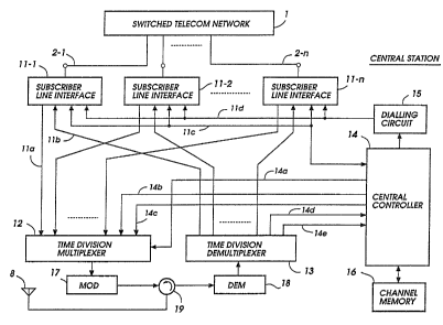
7 Referring to Fig. 2, the central station 3 includes subscriber line
8 interface circuits (SLIC) 11-1 through 11-n connected respectively to the
9 exchange subscriber lines 2-1 through 2-n. Each subscriber line interface
lû circuit 11 is provided with a hybrid which converts the two-wire
l 1 subscriber line 2 to a four-wire circuit having an outgoing line 11a
l 2 connected to a respective input of a time division multiplexer 12 and an
13 incoming line 11b connected from a respective output of a time division
l 4 demultiplexer 13. Subscriber line interface circuits 11 are connected by a
respective two-way line 11c to a central controller 14 to exchange control
16 signals with the network 1 and are connected by a line 11d to the output of17 a dialling circuit 16 which operates to dial an ernergency call destination18 address as will be described later. Time division multiplexer 12 is
19 associated with the central controller 14 to multiplex signals from the line
interface circuits 11 into a selected idle speech channel in response to a
21 control signal supplied on a control line 14a from the controller 14.
2 2 Control signals to be supplied to the remote stations are carried on a
2 3 line 14b from the controller 14 to an associated input of the multiplexer 12
24 and emergency call signals are supplied on a line 14c and fed to an
2 s associated input of the multiplexer. These control signals are respectively
26 transmit-ted on control and emergency channels, or time slots, and
2 7 multiplexed with other speech signals carried on selected speech channels.28 The multiplexer output is applied to a modulator 17, where it is
2 9 modulated on a radio frequency carrier and supplied through a duplexer
NE- 160
- 7 -
19 to the antenna 8, where it is transmitted as a lD~ down-direction
2 (towards remote stations 4) in a broadcast mode to the remote stations 4.
3 Incoming signals from the remote stations 4, detected by antenna ~3,
4 are supplied through duplexer 19 to a demodulator 18, the output of
S which is fed to the demultiplexer 13. Demultiplexer 13 examines the
6 control channel to identify the address of the speech channel signals and
7 connects the identified channels through incoming lines 11b to the
8 appropriate line interface circuits 11. Demultiplexer 13 f~rther separates
9 the control channel, the emergency channel or specified speech channel
1 0 and supplies control signals carried on the control channel on line 14d to
1 1 the controller 14 and supplies emergency control signals carried on the
1 2 emergency or specified speech channel on line 14e to the controller 14.
1 3 Controller 14 constantly monitors the busy/idle status of all the
1 4 TDM channels and updates a channel memory 16. This channel memory
1 5 is called upon by the central controller 15 each time as it assigns a speech
1 6 channel to a call request from any of the subscriber terminals 6 or from the
1 7 telephone network 1. When all the speech channels are busy, an "all busy"
l 8 signal is broadcast to the remote stations.
1 9 In Fig. 3, each remote station 4 receives the broadcast TDM signal
2 0 from the central station 3 via antenna 9 and duplexer 20. A demodulator
2 l 21 recovers the baseband TDM signal and feeds a time division
22 demultiplexer 22 where the signal is demultiplexed into respective
23 channel components. The demultiplexed speech channel signals are
2 4 supplied on lines 23b to subscriber line interface circuits 23-~ through 23-n
which are provided in a one-to-one correspondence to the subscriber
2 6 terminals 6-1 through 6-n. The demultiplexed channel control signal and
27 emergency control signal are supplied on lines 24a, 24b to a remote
28 controller 24. Originating registers 25-1 through 25-n are associated
2 9 respectively with subscriber line interface circuits 23-1 through 23-n. As
~:9~7(3~
NE- 160
- 8 -
will be described, each register 25 is designed to detect "on-hook" and
2 "off-hook" and "hook flash" conditions when -the associated subscriber
3 goes off-hook for originating a call, or goes on-hook for terminating a
4 call and signals the detected subscriber line conditions to the remote
S controller 24 on line 24f. If a subscriber desires to place an emergency call,
6 but hears a busy tone indicating that all the speech channels are busy. The
7 subscribers instructed to momentarily depress the switchhook under such
8 conditions to alert the system of an emergency. The register detects the a
9 "hook flash" condition and sends a dial tone to the requesting terminal to
10 urge the subscriber to dial the desired emergency call destination. The
11 emergency destination address is detected by the originating register 25
2 and fed to the remote controller 24 to be transmitted to central station 3.
13 Each subscriber line interface circuit 23 has an outgoing line 23a
14 connected to a respective input of a time division multiplexer 26 to which
15 the channel control signal and emergency control signal from the remote
16 controller 24 are also supplied on lines 24c, 24d. Multiplexer 26 is
17 controlled in response to a channel identification signal supplied on line
18 24e from the remote controller 24. The output of multiplexer 26 is
19 coupled to a modulator 27 where the baseband TDM signal is modulated
2 0 on a radio frequency carrier and applied through duplexer 20 to antenna 9
21 and transmitted to the central station as a TDM up-direction signal.
2 2 Central controller 14 and remote controller 24 are implemented by
23 microprocessor-based controllers each being programmed according to
2 4 embodiments of the present invention.
2 5 Figs. 4A and 4B are flowcharts describing the operations of remote
26 and central controllers 24 and 14, respectively, according to a first
27 embodiment of the present invention. l~ach of the TDM up- and down-
2 8 direction links of the first embodiment is divided into time slots as shown
2 9 in Fig. 7. Time slot # 0 is e~clusively used for the transmission channel
~2~3'7(3
NE- lG0
g
control and system management control signals and time slots ~t1 and #2
2 are reserved for emergency calls. The other time siots are syeech
3 channels for carrying speech signals. In ~ig. 4A, the program execution of
4 remote controller 24 starts with a decision block 30 which checks to see if
S any of the subscriber terminals goes off-hook. If an off-hook condition
6 occurs, an associated originating register 25 issues a call request to the
7 controller 24 and the program control proceeds to a decision block 31 to
8 detect whether the controller 24 has received an "all busy" signal on the
9 control channel from the central station.
1 û If there is an idle speech channel in the transmission link, the answer11 is negative in block 31, exit is to operations block 41 which directs the
12 sending of a speech channel assignment request (SCAR) to the central
13 station on the control channel to elicit a response from the central station
~ 4 indicating the identification of an assigned speech channel. Control then
15 proceeds to decision block 42 to check for the reception of such a response.
16 As will be understood as the description proceeds, the central
l 7 controller 14 receives the speech channel assignment reques-t, selects an
18 idle speech channel by looking up the contents of the channel memory 16
19 and assigns the selected channel to the requesting subscriber. Central
20 controller 14 proceeds to send the identification number (ID) of the
21 selected speech channel on the control channel to the remote station and
22 establishes a connection between the subscriber line interface circuit
23 (SLIC) 11 concerned with the assigned speech channel. The ID of the
2 4 selected speech channel is received by the remote controller 24 (block 42),
2 5 which is followed by operations block 43 -to establish a connection between26 the subscriber line interface circuit 23 of the calling subscriber to the
2 7 assigned speech channel, thus setting up a dialling connection.
28 If al! the speech channels are busy, the remote controller 24 has
2 9 received an "all busy" signal from the central station and the answer is
NF.- 160
- 10-
affirmative in block 31. Exit then is to operations block 32 which directs
2 the sending of a busy tone from the associated subscriber line interface
3 circuit 23 to the calling subscriber and thence to decision blocks 33 and 34
4 to check -to see if the subscriber goes on-hook or momentarily depresses
the switchhook. If the subscriber goes on-hook on hearing the busy tone,
6 control returns to block 30. If the subscriber wants to place an emergency
7 call, he will momentarily depress the switchhook, sending a "hook flash"
8 signal to the remote controller 24. Thus, control exits from block 34 to
9 operations block 35 which directs the removing of the busy tone and
l O sending of a dial tone from the associated originating register 25 to the
1 l subscriber terminal to urge the subscriber to dial an emergency
l 2 destination address.
13 Exit then is to decision block 36 to receive and store the emergency
l 4 destination address in memory and verify the emergency call. This is
accomplished by detecting a match between the diallecl emergency
l 6 destination address against a list of emergency destination addresses
l 7 stored in the remote controller 24. If no match occurs, control goes to
l 8 operations block 44 to send a busy tone to the subscriber. If the call is
l 9 verified, control proceeds to operations block 37 which directs the sending of an emergency channel assignment request (ECAR) on the control
2 l channel to the central station 3 to elicit a response from the central station
2 2 indicating the identification of an assigned emergency channel, and then
23 exits to decision block 38 to check for the reception of the emergency
2 4 channel identification number. Exit then is to operations block 39 which
2 5 directs the switching of the subscriber line interface circuit 23 concerned to
26 the assigned emergency channel and thence to operations block 40 to
27 transmit the stored emergency destination address to the central station
2 8 on the assigned emergency channel.
2 9 As will be described, this emergency call request will be received by
NE- 160
- 11 -
the central controller 1a~ and one of the emergency channels is selected and
2 assigned to the calling subscriber. The ID of the selected emergency
3 channel is returned on the control channel and the reception of this signal4 is confirmed by the remote station concerned (block 38). If no emergency
channels are available, exit is to block 44 to send a busy tone to the
6 subscriber.
7 In Fig. 4B, the program execution of the central controller 14 begins
8 with operations block 50 which directs the updating of the channel
9 memory 16 with an assigned channel identification number. Exit then is
1 û to decision block 51 which checks to see if all the speech channeJs are busy1 1 and proceeds to operations block 56 to send an "all busy" signal on control12 channel if the answer is affirrnative or proceeds to decision block 52 if the
13 answer is negative. With block 52, the remote controller 24 awaits the
14 arrival of a speech channel assignment request (SCAR) from a remote
station requesting an ordinary or emergency call. On receiving a SCAR
16 signal, control exits to operations block 53 which directs the selecting o~17 an idle speech channel using the information stored in the channel
18 memory 16 and the assigning of the selected speech channel to the calling
19 subscriber. Exit then is to operations block 54 to transmit the ID of the
2 0 assigned speech channel to the remote station on -the control channel and
21 advances to operations block 55 to connect the subscriber line interface
2 2 circuit 11 of the calling subscriber to the assigned speech channel. Thus,
2 3 control loops through blocks 50 to 55 when a call request is received from24 any of the remote stations provided that at least one speech channel is
2 5 available.
2 6 With block 56, the central controller 14 sends an "all busy" signal to
2 7 remote stations 4 and proceeds to block 57 to check for the arrival of an
2 8 emergency channel assignment request (ECMR). If there is one, control
2 9 proceeds to operations block 58 to select an idle emergency channel and
~2~'70~;
NE- 160
- 12-
assign it to the emergency calling subscriber and advances to operations
2 block 59 to send the ID of the assigned emergency channel on the control
3 channel to the remote station. Exit then is to operations block 60 which
~-~ directs the connection of the subscriber line interface circuit 11 of the
5 emergency caller to the assigned emergency channel and control proceeds
6 to decision block 61 to receive a dialled emergency destination address
7 from the remote station on the assigned emergency channel. On receiving
8 the emergency destination address, central controller 14 supplies it ~o the
9 dialling circuit 15, whereupon it dials the received address to the public
10 network 1 through the s~bscriber line interface circuit 11 of the emergency
1 1 calling subscriber (block 62).
12 To summarize the operation of the first embodiment of the
l 3 invention, Fig. 4C shows a sequence of events that occur when an
14 emergency call is originated from terminal 6-1, for example, under an all-
15 busy condition. A hook-flash signal from the terminal ~1 is detected by
16 remote station 4-1 (block 34), causing a dial tone to be sent to the terrninal
l 7 6-1 (block 35) from remote station 4-1 to urge the subscriber to dial a
l 8 desired emergency destination address. After verifying the dialled
19 information, remote station 4-1 sends an emergency channel assignment
2 0 request on the control channel to central station 3 (block 37) and received
2 l by the central controller 14 (block 57). An idle emergency channel is
22 assigned to the terminal 6-1 (block 58) and the identification of the
23 assigned emergency channel is sent from central station 3 to remote
2 4 station 4-1 (block 59) on the control channel. The emergency channel ID is
25 received by remote controller 24 (block 38). Subscriber line interface
2 6 circuits 23-1 and 11-1 of the remote and central stations are connected to
2 7 the assigned emergency channel (blocks 39, 60) and the dialled destination
2 8 address is sent from remote station 4-1 to central station 3 (block 40) and
29 then relayed to '~he public network 1 (blocks 61, 62) to establish a
NE- 160
- 13-
connection between the terminal 6-1 and the emergency destination.
2 A second embodiment of the present invention is shown in Figs. 5A,
3 5B and 5C. This embodiment differs frorn the first embodiment in that it
4 includes blocks designated 100 through 107. After verifying the emergency
S call (block 36) from tern~inal 6-1, the remote controller 24 o~ station 4-16 proceeds to operations block 100 which directs the sending of an
7 emergency access grant request (EAGR) signal on one of the emergency
8 channels to central station 3. This EAGR signal is received by central
9 station 3 (block 104). Control proceeds to decision block 105 to check to see
if there is a collision with another emergency call. If there is one, control
returns to block 50, and if there is none, exit is to operations block 106
12 which directs the sending of an access grant signal on the emergency
13 channel to the remote s-tation 4-1 and control advances to operations
14 block 107 to connect the subscriber line interface circuit 11-1 to the granted
emergency channel. When this grant signal is received by remote station
l 6 4-1 (block 101), the remote controller 24 proceeds to block 102 to connect
17 the subscriber line interface circuit 23-1 to the granted emergency channel.
l 8 Exit then is to operations block 103 which directs the sending of the stored
19 emergency destination address on the granted emergency channel to the
central station. Central station 3 receives the emergency destination
21 address (block 61) for transmission to the network 1 through dialling
2 2 circuit 15 (block 6~). It is seen that with the second embodiment of the
2 3 invention all control signals are sent via one of the emergency channels
24 and the central station operates to grant permission to the use of the
2 S emergency channel if no data collision occurs between emergency calls.
2 6 A third embodiment of the present invention is shown in Figs. 6A, 6B
2 7 and 6C. The third embodiment differs from the first embodiment of the
2 8 invention in that it includes blocks designated 200 through 212. In this
2 9 embodiment, emergency channels are not provided as shown in Fig. ~ and
NE- 160
- 14-
emergency calls established when an all busy cond;tion exists by forcibly
2 clearing one of the speech channels which may be used by a remote station
3 other than the emergency requesting remote station 4-1. The program
4 starts decision block 200 which checks for the reception of a disconnect
S signal from central station 3. If there is none, exit is to decision block 30 to
6 perform executions similar to those of Fig. ~A until control proceeds to
7 block 37 in which the remote station, i.e., station 4-1 requesting the
8 emergency call under an all busy condition sends an emergency channel
9 assignment request on the control channel to the central station. On
10 receiving this request (block 57, Fig. 6B), the central station proceeds to
11 operations block 206 to select one of the speech channels and transmits a
12 disconnect signal indicating the channel number of the selected speech
13 channel on the control channel to a remote station associated with the
14 cleared channel (block 207). Exit then is to operations block 208 which
1 5 directs the clearing of the selected channel and thence to decision block 209
16 which checks to see if a clear response signal is received.
17 The remote station, which is associated with the speech channel to
18 be cleared, receives the disconnect signal addressed to it (block 200, Fig.
19 6A) and proceeds to operations block 204 which directs the clearing of a
speech channel specified by the received disconnect signal. Exit then is to
21 operations block 205 which directs the sending of a clear response signal
22 to central station 3 on the control channel indicating that the specified
23 speech channel has been cleared. On receiving the clear response signal
24 (block 209, Fig. 6B), the central station proceeds to operations block 210
which directs the sending of the identification number of the cleared
26 speech channel to the emergency call requesting station and thence to
27 operations block 211 which directs the connecting of the subscriber line
28 interface circuit 11-1 to the cleared channel. The cleared channel
29 identification signal is received by remote station 4-1 (block 201) and the
NE- 160
- 15 -
latter proceeds to operations block 202 which directs the connecting of the
2 subscriber line interface circuit 23-1 to the cleared speech channel. Exit
3 then is to operations block 203 which directs the sending of the stored
4 emergency destination address on the cleared channel to the central
5 station. On receiving the destination address signal (block 212), the
6 central station advances to operations block 62 to send the emergency
7 destination address through dialling circuit 15 to the network 1.
8 The foregoing description shows only preferred embodiments of
9 the present invention. Various modifications are apparent to those
10 skilled in the art without departing from the scope of the present
1 1 invention which is only limited by the appended claims. Therefore, the
12 embodimen-ts shown and described are only illustrative, not
1 3 restrictive.