Note: Descriptions are shown in the official language in which they were submitted.
~,~9g7~9
TIT:LE O:F T~IE INV~NTION
MUL.TIPLF-FlB~R OPTI~AL COMPONENT ~ND
M~'rll~D FOI~ MANUF~CTURIN~ O~ Tll~ ~M:~
Bl~CKGROUN~ OF T~IE I~VENTI~N
'rhe present invention rela-tes to a multiple-fiber
optical component suitable for use with multiple
optica:L fibers and havlng various ~unctions and a
method for manufacturin~ the same with ease and wi-th a
high acouracy.
Recently, with development of multiple-fiber
optical cables, such as a ribbon fiber and improvement
of wavelength division multiplexing technique and the
like, the importance of multiple-f'iber wavelength
division multiplexers/demultiplexers, mul-tiple-fiber
optical couplers/split-ters, and the like is
significantly increased.
Conventionally, as multiple-fiber optical
components, there are a system that has a desired
number of optical components jux-taposed to each other
each with a single-fiber s-tructure having a branch-path
optical fiber obliquely spliced to a strai~h-t-path
optical fi'ber, and a multiple-f'iber optical connector.
~lowever, production of the conventional optical
components having optica:L fibers obliquely spliced
together needs, for instanoe, a jig for ~arious axial
alignments in -the course of assembly of the components,
so that -these components are not so much effective as
multiple-fiber optical components. Fur-ther, in a
multiple-fiber optical system, multiple-fi'ber to
sin~le-fiber conversion is required for transmission of
optical si~nals between a multiple-fiber ribbon and a
sin~le fiber. What is more, conventionally, a
~9~7~79
wavelen~th division multiplexingtdemul-tiplexing prooess
for an opt:ical sia~nal with more than two waveLengths
needs two or more optical components, and a change in
-the operating wavelength necessitates a comple-te
replacement of the op-tical componen-ts. In this regard,
-the conventional multiple-fiber optical components are
inconvenient in designing optical systems.
~BJ~TS AND SUMMARY OF TH~ INVENTION
It is an object of this inven-tion to provide a
mul-tiple-fiber optical component designed to ensure
axial alignmen-t of optical fibers with ease and to
prevent insertion loss due to axial misalignment of
fibers, and a method for manufacturing the same.
It is another object of this invention to pro~ide
a multiple-fiber op-tical component suitable for use
with a multiple optical fibers and a method for
manufacturing the same accurately with a simple
process.
It is a fur-ther object of this invention to
provide an optical component which can be provided with
a waveleng-th division multiplexing/demultiplexing
function and permits alternation of the opera-ting
wavelength as desired, and hence which is convenient in
designin~ an optical system and is inexpensive.
It is a further ob,ject of -this invention to
provide a compact and inexpensive multiple-wavelength
and multiple-fiber wavelength division
mul-tiplexer/demultiplexer for optical signals with
multiple-wavelengths.
It is a further object of this invention to
provide a mul-tiple-fiber optical component wi-th a
function for conversion between a multiple-fiber ribbon
779
and a single f:iber and a method f`or manufacturing the
same.
It is a further object o~ -this invention to
provide a mul-tiple fiber optical co~ponent having a
built-in mul-tiple-fiber/single-fiber conversion unit
and a multiple-fiber/single-fiber conversion function.
It is a s-till further object of this invention to
provide a me-thod for manufacturing a multiple-fiber
optical component, which reduces occurrence of defects
due to variation in the leng-th of an optical fiber
disposed in a case of the mul-tiple-fiber optical
component to thereby improve the yield and eliminates
the need for an otherwise troublesome process for
ma-tching the lengths of op-tical fibers in use.
According to one aspect of -this invention, there
is provided an optical component, which comprises at
least first through third blocks having a plurality of
parallel guide grooves formed on each of' their
surfaces, an optical fiber being placed and fixed in
each of -the guide grooves and having an inclined face
at one end, the optical fibers of the first and seoond
blocks having their inclined faces or slan-t ends
join-ted together through a first optical fil.m in such a
way that their optical axes are aligned with each
other, the optical fiber of the third block having a
second optical filrn formed on -the one end face and
being disposed in such a way that its optical axis is
in parallel -to the optioal axes of the optioal fibers
of the first and second blocks and when an optical
signal incident to the op-tical fiber of the first block
is successively reflected a-t the first and second
optical films, the optical signal is propagated along
the optical axis of the optical fiber of the -third
~:~9~
~,
bloGk .
According to another aspect of this invention,
there is provided a method for manufacturing an optical
component, which comprises the s-teps of forming a
plurality of parallel optical fiber guide ~rooves and
at least one alignment-pin guide groove in each of'
surfaces of at least first through third block members,
to ob-tain at least first through third blocks; placing
and fixing optical fibers in the respective optical
fiber guide grooves of the firs-t to third blocks;
obliquely polishing or lapping one end of each of the
first to third blocks toge-ther with the optical fibers
placed thereon to thereby form an inclined face;
forming a firs-t optical film on the inclined face of at
least one of the first and second blocks and then
arranging the first and second blocks in such a way
that when an optical signal incident to th~ optical
fiber of the first block passes through the first
op-tica:L film, the op-tic~l signal is propagated to th~
op-tical fiber of the second block; forming a second
optical film on the inclined face of the third block
and -then arranging the third block in such a way that
an op-tical axis of the op-tical eiber of -the third block
is in ~parallel to optica:L axes of the optical fibers of
the fi:rs-t and second blocks and when an optical signal
incident to the optical fiber of -the firs-t block is
successively reflected at the first and second optical
films, the optical signal is propagated to the op-tical
fiber of' the third block; and disposing a common
alignment pin in the alignment-pin guide grooves
respectively formed in the first to third blocks and
fi-tting and fixing the f.irst to third blocks together
by the common alignment pin.
- 6 --
~ ccording to a fllrther aspect of -this invention,
there is provided a multiple-fiber op-tical Gomponent
which comprises a first substrate formed on its surface
with a plurality o- parallel guide grooves and a slit
crossing the guide grooves and extending from the
surface of the first substrate to an opposite surface
thereof at a predetermined angle. An optical film is
fittecl in the slit, and a straight-path optical fiber
is placed and fixed in each o:E the guide grooves in
such a way that optical axes of both sides of the fiber
with respect to the optical film interposed
therebetween are aligned with each other. Further, a
branch-path optical fiber, placed and fixed in a
respective one of parallel ~uide grooves formed in a
surface of a second substrate, is disposed in contact
with an outer periphery or circumference of an
associated one of the straight-path optical fibers in
such a way that when an incident optical signal to a
respective one of the straigh-t-pa-th optical fibers is
reflected at the optical film, the optical signal is
propaga-ted along the optica:L a~is of an associated one
of the branch-path optical fibers.
~ ccording to a further aspect of this invention,
there is provided a method for manufacturing a
multiple-fiber optical component, which comprises the
steps of forming a plurality of parallel shallow guide
grooves on a first plate at a substantially middle
portion of its surface, to obtain a firs-t substrate;
disposing and fixing a straight-pa-th optical fiber in
each of -the guide ~rooves; forming a slit cros~ing the
s-traight-pa-th optical fibers and extending fronn the
surface of the first substrate -to an opposite surface
thereof at a predetermined angle; -fitting and fixing an
7~9
-- 6
optica:l film in the sli-t; disposing and fixing branoh-
path optioal fibers in a plurality of parallel guide
grooves formed in a surf`ace of a second substra-te
obtained from a second plate; and a:rranging a
respective one of the branch-path optical fibers in
contact with an outer periphery of an associated one of
the straigh-t-pa-th optical fibers in such a way that
when an incident optical signal to a respective one of
the straigh-t-path optioal fibers is reflected at the
optical film, the optical signal is propagated along
the optical axis of an associated one of the branch-
path optical fibers.
According to a further aspect of this invention,
there is provided an optical component which comprises
a first substrate with an optical fiber disposed and
fixed on a surface thereof in its lengthwise di.rection,
an op-tical film fittedly fixed in a slit crossing the
optical fiber and extending from -the surface of the
first substrate to an opposite surface thereof at a
first predetermined angle, so as to be adapted -to be
jointed to an external optical component, and an
alignment pln for axial alignment which is disposed on
the surface of -the firs-t substrate in the lengthwise
direction thereof, and, preferably, in parallel with
the optical fiber, so as -to be adap-ted to be fitted to
-the external optical component. Further, an optical
component is provided, which comprises a second
substrate with an op-tical fiber disposed and fixed on a
surface thereo-f in its lengthwise di:rection, an optical
film fittedly fixed in a slit crossing the optical
fiber and extending from the surface of -the second
substra-te to an opposite surface thereof at a first
prede-termined angle, so as to be joinable to an
e~-ternal optical component, and an alignmen-t-pin guide
groove provided on the surface of the second subs-trate
in the lengthwise direction thereof, and, preferab:Ly,
in parallel wi-th the optical fiber, so as to be adapted
to receive an alignment pin, for axial alignment, of an
external op-tical component. Furthermore, there is
provided an optical component which comprises a third
substrate with an optical fiber disposed and fixed on a
surface thereof in its lengthwise direction, a total
reflec-tion film fittedly fixed in a slit crossin~ the
optical fiber and extending from the surface of the
third substrate to an opposite surface thereof at a
second predetermined angle, so as to be joinable to an
external optical componen-t and an alignment-pin guide
groove provided on the surface Oe the third substrate
in the lengthwise direction thereof, and, preferably,
in parallel with the optical fiber1 so as to be adapted
to receive an alignment pin, for axial alignment, of
-the external optical component.
~ ccording to a further aspect of this invention,
there is provided a multiple-wavelength multiple-fiber
type of waveleng-th division multiplexer/dell~ultiplexer
which comprises a common substrate for straight-path,
formed with a plurality of parallel optica:L fiber guide
grooves provided on its surface in a lengthwise
direction -thereof in which straight-path optical fibers
are disposed and fixed, and a plurality of straight-
path op-tical films with different characteristics being
fittedly fixed respectively in a plurali-ty of slits
provided on the surface of the common substrate, each
crossing the straight-path cptical fibers and extending
from -the surface thereof to an opposite surface thereof
at a predetermined angle, each of branch-pa-th
g
substrates ls formed at its surface with a -plurali-ty of
parallel optical fiber guide grooves formed in a
lengthwise direc-tion thereof. Branch-path optical
films with differen-t characteristics are fi-ttedly fixed
in slits respectively formed on the surfaces of the
branch-path substrates so as to cross -the op-tical
fibers and extencl from the surfaces thereof to opposite
surfaces -thereof at predetermined angles at which the
slits of the common substrate extended. The branch-
path subs-trates are disposed in contact with and fixed
to the straight-path common substrate in such a way
that the straight-path optical films of the common
substrate are op-tically aligned with -the optical films
of the branch-pa-th substrates in association of the
charac-teristics of the branch-path optical films with
the characteristic of the straight-path optical films.
According to a further aspect of this invention,
there is provided a multiple-fiber optical component
with a multiple-fiber/single-fiber conversion func-tion,
which comprises a main body havin~ two or more
input/output ports for execu-ting a multiple-
fiber/single-fiber conversion, and at least one single-
fiber input/ou-tput means and multiple-fiber
inpu-t/output means provided at the input/output ports
of -the main body, and a method for manufacturing the
same.
According to a further aspect of this invention,
there is provided a multiple-fiber optical component
with a multiple-fiber/single-fiber conversion function,
which comprises a multiple-fiber op-tical component with
two or more multiple-fiber input/output ports, and a
mult:iple-fiber~single-fiber conversion component,
Goupled to at least one of the multiple-fiber
~,r~1~9 '
input~output por-ts, for e~ecu-ting a multiple-
fiber/sin~le-fiber conversion. The multiple-
fiber~in~le-fiber conversion component inolude~ N (=2,
3, ~, ...) sin~le fibers having different terminations
at both ends, the respective one of terminati.ons of
these fibers being attached together to an N-fiber
ferrule at one end and the respective one of the other
terminations of these fibers consisting of at least one
of a single fiber and/or a single-fiber ferrule
connec-ted to a single fiber at the other end.
According to a further aspect of thi~ invention,
there is provided a method for manuEacturing a
multiple-fiber optical component having a cain body and
an input/output connector to be coupled to the main
body, which method comprises the steps of forming a
bottom substrate portion of the main body and an
input/output connector portion on a common substrate;
disposing and fi~ing optical fibers -to the input/output
connector portion; disposing and fixing free end
portions of -the optical fibers to -the bottom substrate
portion without bending the free end portions; and
e~ecuting a necessary process to the bottom substrate
portion to form a bottom portion of the main body.
The above-merrtioned optical film may consist of an
ele~ent selected from a group consisting of wavelength
selec-tive film, spli-tting film, total reflection film,
the above-mentioned film with -transparent substrate and
the like, in accordance with a kind of an intended
optical component -to which this invention is applied.
The above objects and other object as well as
other features and advantages of this invention will
become more apparent from the followin~ detailed
description given wi-th reference to the accompanying
~2~
- :~o -
drawin~gs.
B~IEF ~ESC~IPTION OF T~l~ DRAWINGS
Fig. 1 is a diagram illus-trating -the conceptual
structure of one unit of a two-fiber wavelen~th
division mul-tiplexer/demultiplexer according to a first
embodimen-t of this invention;
Fig. 2 is a perspective view of a multiple-fiber
type of wavelength division multiplexer~demultiplexer;
Fig. 3 is a cross section as taken along -the line
III-III in Fig. 2;
Fig. 4 is a cross section of another arrangement
as taken along the line III-III in Fig. 2;
Fig. 5 is an e~ploded perspective view of Fig. 2;
Fig. 6 is a view illustrating a process in a
method of producing a multiple-fiber type of wavelength
division multiplexer/demultiplexer of the present
invention;
Fig. 7 is a diagram illustrating the conceptual
s-tructure of one unit of a conventional multiple-fiber
optical component;
Fig. 8 is a perspective view illustrating the
multiple-fiber optical component unit of Fig. 7
assembled according to the conventional method;
Fig. 9 is a partially cross-sectional perspective
view of a -two-fiber waveleng-th division
multiplexer/demultiplexer accordin~ to a second
embodiment of this invention;
Fig. 10 .s a partially enlarged cross-sectional
view of Fig. 9;
Figs. 11 through 13 are cross sections
illustra-ting processes for manufacturing a multiple-
fiber optioal component of this invention;
7~79
-- 1 1 --
~ i~t~. 14 is a. partially cross-sectional de-tailed
perspective view of a slit forming process shown in
Fig. l2;
Figs. 15 and 16 are oross sections illustrating
alignment pins disposed in alignment-pin guide grooves
and connector guide grooves respectively formed in a
straight-path substrate and a branch-path substrate;
Figs. 17 and -18 are partially cross-sectional
perspective views of two-eiber wavelength division
multiplexers/demultiplexers according to third and
fourth embodiments of this invention;
Fig. 19 is a partiall~ cross-sectional view o~ a
modification of the two-fiber wavelength division
multiplexer/demultiplexer of Fig. 9;
Fig. 20 i8 a diagram for explaining the operation
of th~ optical component of Fig. 19;
Fig~s. 21 and 23 are side views of a straight-path
section and a branch-path section of an optical
component according to a fifth embodiment of this
inven-tion, respectively;
Fig~s. 22 and 24 are side views illustrating
modifications of the optical oomponent as shown in
Figs. 21 and 23;
Figs. 25 through 27 are diagrams for explaining
the operati.on of the optical component of -this
invention;
~ ig. 28 is a par-tially cross-sectional perspective
view of a three-wavelength -two-fiber type of wavelength
division multiplexer~demul-tiplexer according to a six-th
embodiment of -this invention;
Fig. 29 is a cross section as taken along the line
XXIX-XXIX in Fig. 28;
Figs. 30 and 31 are side views illustrating
7~9
- 12 -
modifications of the wavelength division
multiple~er/demultiplexer of Fig. 28;
Fig. 32 is a perspective view illustrating another
modification;
Figs. 33 and 3~ are perspective views respectively
illustrating the internal structure and a case of a
two-fiber optical component according to a seventh
embodimen-t of this invention;
Fig. 35 is a perspective view illustrating a
straight-path section of Fig. 33;
Fig. 36 is a perspective view illustrating a
branch-path section;
Fig. 37 is a longitudinal cross section of a
straigh-t-path substrate;
Fig. 38 is an enlarged transversal cross section
of a center portion of a straight-path substrate in its
lengthwise direction;
Fig. 39 is a perspective view illustrating a
modification of an input/output port of the multiple-
fiber op-tical component of Fig. 33;
Fig. ~0 is a perspective view illustrating a
modification of -the internal structure of the multiple-
fiber optical component;
Fig. ~t is a perspective view illustrating a
modification of the case suitable for -the structure of
Fi~. ~0;
Fig. 42 is a perspective view illustrating the
internal struc-ture of an optical component according to
a modi~ication of the seventh embodiment;
Fig. ~3 is a perspective view of a case of the
same op-tical componen-t;
Fig. ~ is a perspective view illustrating the
internal structure of an op-tical component according to
- 13 -
another nodification;
Fi~ 5 is a perspective view of a oase of the
same optical component;
~ ig. 46 is a longitudinal cross section of a
further modification of the seventh embodiment,
Fig. ~7 is a perspective view illustrating a case
and a peripheral s-tructure of an optical component
according a still further modification;
Fig. ~8 is a perspective view illustrating the
internal structure of the same optical component;
Fig. 49 is a horizontal cross section of the same
optica~ component;
Fig. 50 is a plan view illustrating a common
substra-te of an optical component according to an
eighth embodiment of this inven-tion;
Fig. 51 is a cross section of the same substrate;
Fig. 52 is a plan view illustrating another
substrate constituting, together with the common
substra-te, the same optical component;
Fig. 53 is a plan view illustrating a common
sub3trate for use in a modification of the optical
component according to the eigh-th embodiment;
Fig. 5~ is a diagram illustrating a bending state
of an optical fiber caused at the time of assembling
the op-tical component of Fig. ~9;
Fig. 55 is a perspective view illus-trating the
internal struc-ture of an optical component according to
a ninth embodiment of this invention;
Fig~. 5fi is a perspective view of a modiPication of
a two-fiber/single-fiber conversion component for use
in the optical component of Fig. 55;
Fig. 57 is a perspective view of a modification of
the op-tical component according to the ninth
779
embodiment; and
Fi~g~. 58 is a perspec-tive view of another
moclification.
D~TAIL~D D~SC~I~TION
Before going into an explanation of a multiple-
fiber optical component of -this invention, a
conventional optical component will be explainedO
Conventionally, a multiple-fiber optical component
such as a multiple-fiber wavelength division
multiplexer~demul-tiplexer or a multiple-fiber optical
coupler/splitter, is generally composed of a plurality
of units which are juxtaposed to each other in the
direc-tion vertically of the sheet (Fig. 7), each
consisting of a wavelength multiplexer/demultiplexer or
an op-tical coupler/splitter, with a single-fiber
structure as shown in Fig. 7. In Fig. 7, the single
unit for the multiple-fiber optical component comprises
optical fibers 1, 2 and 3 each having its one end face
obliquely polished, with the optical fibers 1 and 2
being spliced to each other at their polished end faces
through an optical film ~ and -the optical fiber 3 being
spliced to sides of the fibers 1 and 2 in such a manner
that when an optical si~nal incident to the fiber 1 is
reflected at the optical film ~, i-t enters the fiber 3.
With -the above structure, if the op-tical Eilm ~ is a
splitting film, the unit serves as an optical
coupler/split-ter, and if -the film ~ is a wavelength
selective film, the unit serveR as a wavelength
division multiplexer/demultiplexer.
The conventional multiple-fiber op-tical component
has a three-dimensional structure which has these uni-ts
arranged in parallel at prede-termined intervals.
79
- 15 -
~lanufacturin~ this multipl.e-f.iber opti.cal oomponen-t
re~uires axial alignment of the individual optical
fibers. A jig for the alignment has been proposed,
which comprises several blocks as shown in ~ig. 8. The
same reference numerals as used in Flg. 7 are used to
specify iden-tical or corresponding elements in Fig. 8.
A jig 5 is for producing a respective one of the above
units and comprises blocks 6, 7 and 8. The blocks 6
and 7, which receive the optical fibers 1 and 2, have
V-shaped grooves 7a formed on their tops (only the one
on the block 7 side bein~ i.llustrated). After the
optical fibers 1 and 2 are disposed in the respective
grooves, holding bloc~s 6' and 7' are mounted and fixed
on -the respective blocks 6 and 7. The block 8,
disposed between the holding blocks 6' and 7', consists
of two block halves 8a and 8b which are obtained by
cutting a block member at an angle to be defined by the
optical fiber 3 and the optical fibers 1 and 2. One of
the block halves, for example, 8a, has a guide groove
8a' formed for securi.ng the optical fiber 3, while the
other block 8b serves as a holdin~ block.
In applying the jig ~ to manufacturing the
aforernentioned multiple-fiber optical component, the
axial alignment of the optical fibers of each unit is
performed, with the individual optical fibers disposed
and secured to the ji~ 5, to obtain a finished uni-t,
and hence these finished units may be put together to
provide the componen-t.
With the use of such a jig, however, as i.t
includes an oblique axis as formed by the optica:L fiber
3, it is necessary to execute axial alignment for
rotation and parallel alignment of the individual
optical fibers in addition to axial alignment in the X-
- 16 -
, Y- and Z-axial directions~ This significantly
complicates the assembling prooess and thus makes i-t
significantly difficul-t to apply the jig to production
of multiple-Piber optical componen-ts.
Fi~s. 1 and 2 illustrate a two-fiber waveleng-th
division multiplexer/demultiplexer according to the
first embodiment of this invention. Fig. 1 illustrates
-the arrangement of the individual optical fibers in one
unit o~ the two-fiber wavelength division
multiplexer~demultiplexer, in which optical fibers 11
and 12 having their free ends o~liquely polished are
spliced in such a way that their optical axes are
aligned straight through a wavelength selective film
1~. An optical fiber 13 has its free end obliquely
polished or lapped and has a -total reflection film 15
formed on the polished end, and -the fiber 13 is jointed
to the sides of the fibers 11 and 12 in such a way that
its op-tical a~is is in parallel to the axes of the
fibers 11 and 12 and when an incident op-tical signal to
the fiber 11, as indicated by the arrow, is
successively reflected at the wavelength selective film
1~} and -the to-tal reflec-tion film l51 the optical signal
is propagated along the optical axis of the fiber 13.
In -the above arrangement, the wavelen$-th selective
film 1~ may be constituted by a dielectric multi-
layered fillll deposited on the end face of the op-tical
fiber lL or 12 through evaporation, so tha-t an optical
signal with a waveleng-th A1 is passed there-through and
an optical signal with a wavelength ~2 is reflected by
the film. The total reflection film 15 is arranged to
cause -total reflec-tion of an optical signal with the
waveleng-th A2. When optical si$nals with the
wavelengths A1 and A2 are incident to the optical fiber
'77~
-- 17 -
11, therefore, the signal with the wavelength ~1 passes
-through the wavelength selec-tive film 1~ and enters the
opticaL fiber t2 while the other signal with the
waveleng-th ~2 is reflected at the fil-ter 1~ first and
then at the total reflection film 15 and en-ters the
fiber 13, thereby demul-tiplexing two optical signals
with different wavelengths.
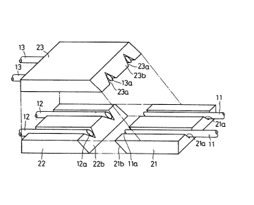
Fig. 2 illustrates the overall structure of the
above~mentioned two-fiber wavelength division
multiplexer/demultiplexer, in which a block 21, having
the optical fibers L1 disposed and secured in guide
grooves 21a, and a block 22, having the optical fibers
12 disposed and secured in guide grooves (not shown3,
are bu-t-t-jointed at their inclined faces 2Ib and 22b
and a block 23, having the optical ~ibers 13 disposed
and secured in guide grooves 23a, is jointed at its
bottom to -the tops of the blocks 21 and 22.
Fig. 3 illustrates the cross section of the
optical component of Fig. 2 along the line
perpendicular to the optical axes of the optical
fibers. As illustra-ted, the guide grooves 22a of -the
block 22 and the guide grooves 23a of the block 23 are
formed such tha-t their a~sociated edge portions are
comple-tely aligned with each other. As -the guide
grooves 21a of the block 21 are the same as the guide
grooves 22a and 23a, their explanation will be omit-ted.
The optical fibers 12 and 13 are disposed in the
respective guicle grooves 22a and 23a and secured by
adhesives l6. It is desirable tha-t each of the guide
grooves 22a and 23a has such a cross section that when
the op-tical fibers 12 and 13 are disposed in the
grooves, the outer peripheries of the fibers 12 and 13
are -flush at their radially outermost locations with
7~
- 18 -
the surfaces of -the blocks 22 and 23. With this
arrangement, when the blocks 22 and 23 are tjoin-ted,
their surfaces are brought into contaot with eaoh other
so tha-t the outer surfaces of opposing optical fibers
also would have a line contact along the optical axis
direction, thus improving the overall mechanical
strength. If the guide grooves 22a and 23a are too
deeper than the outer diameters of the optical fibers
12 and 13, unlike what is shown in Fig. 3I there would
be a gap between the opposing fibers 12 and 13 when the
blocks 22 and 23 are jointed together, this gap causing
radiation loss. On the other hand, if -the guide
grooves 22a and 23a are too Yhallow with respect to the
outer diameters of the fibers 12 and 13, the surfaces
of the blooks 22 and 23 would not contact each other,
with only the fibers 12 and 13 having a line contact to
each other in the optical axial direction, in jointing
the blooks 22 and 23 together. The overall structure
therefore becomes meohanioally unstable.
It is also desirable tha-t, as shown in Fig.
(only blocks 22 and 23 being illustrated), the
individual blocks 21-23 have ~uide grooves 21c-23c
(only -the grooves 22c and 23c are shown) of, for
example, a V cross section, for receiving alignment
pins 30, which are common to these blocks and by which
-the individual blooks are fitted together.
Fig. 5 is an exploded illus-tra-tion of the two-
fiber wavelength division Multiplexer/demul-tiplexer of
Fig. 2 In the surface of the first block 21 are two
parallel guide grooves 21a of, for example, a V-shape,
formed at a predetermined interval therebetween for
receiving and securing the optical fibers 11.
Similarly, two parallel guide grooves 22a for receiving
~ 79
Ig
and securing -the optical fibers 12 and two parallel
guide grooves 23a receiving and securing the optical
fibers 13 are formed respectively in the surfaces of
the blocks 22 and 23 at the same interval therebetween
as that of the guide grooves 21a. The polished
inclined end faces 11a, 12a and 13a of the op-tical
fibers 11-13 and the end faoes 21b, 22b and 23b of the
blocks 21-23 on which these fibers 11-13 are secured
are designed so as -to be flush with each other. The
end face of either the optical fiber 11 or 12, for
example, the end face 1la, ha~ a wavelength selective
film deposited thereon through evaporation and the end
face 13a of the optical fiber 13 has a total reflection
film formed thereon. The block.s 21 and 22 are butt-
join-ted at their end faces 21b and 22b and at the same
time, the opt:ical fibers 11 and 12 are butt-jointed at
their end faces 11a and 12a. The block 23 is securely
jointed to the blocks 21 and 22, with its bottom
closely contacting with the tops ot` the blocks 21 and
22.
When the individual blocks with the associated
optical -eibers secured thereon are ,jointed together in
the above manner, as -the fibers 11-13 cons-titute the
individual units Oe the waveleng-th division
multiplexer/demultiplexer shown in Fig. 1, a two-fiber
wavelength division multiplexer/demul-tiplexer can be
provided as a consequent.
The following explains an example Oe a process for
manufacturing -the above two-fiber wavelength division
multiplexer/demultiplexer to which the manufacturing
method of this invention is applied.
~ irst, parallel eiber guide grooves 21-23, two
each, and parallel pin guide grooves 21c-23c, also two
779
- 20 -
each, are formed in the surfaces of the first to third
blocks 21-23l and -the optical fibers 11-13 are disposed
in the respective ~uide grooves 21a-23a and secured
there by adhesives (see Figs. 3 and ~. Then, one end
of each block, 21b, 22b or 23b, is obliquely cut
together with i~s associated fibers and then polished.
It is desirable tha-t this step is executed using a
micro-lapping technique which ensures simultaneous
cutting and polishing. In this step, i one continuous
block Inember 20 having two parallel guide grooves 20a
formed as shown in Fig. 6 is subjected to the micro-
lapping process to be cut and polished at its proper
section along the face indicated by the broken line A
in Fig. 6 to be thereby separated in-to the first and
second blocks 21 and 22, these blocks 21 and 22 can be
completely fitted together, thus preventin~ insertion
loss due to a axial misalignment.
In the next s-tep, as shown in Fig. 4, the
alignment pins 30 are fitted in the respective pin
guide grooves 21c-23c (only 22c and 23c being
illustrated) of the blocks 21-23 ~only 22 and 23 being
illustrated) and the blocks are aligned in position
with each other and then secured. At this time, axial
ali~nment of the optical fibers 11-13 disposed and
secured on -the respective blocks 21-23 can be done by
shifting -the blocks back and forth along the alignmen-t
pins 30. This is advantageous in that a prooess for
the necessary axial alignment of the op-tical fibers is
significantly simplified. The alignment pins 30 may be
fitted in pin ~uide grooves formed in a micropositioner
of a micro-lapping machine (not shown) so as to provide
reference positions for block alignment in the block
cu-tting s-tep.
~79
- 21 -
.\lthough the above embodiment has been described
with the two--fiber wavelength d:ivision
mul-tiple~er/demultiplexer consti-tuted b~ three blocks,
the nu~ber of the blocks is not specifically limited
thereto and may be properly selected in accordance with
the structure of the multiple-fiber optical component.
Fig. 9 illustra-tes a two-fiber wavelength division
multiplexer/demultiplexer according to the second
embodiment o~ this inven-tion, in which parallel guide
grooves (V groovas) 102 ~nd 103 are formed in the
surface of a straight-path substrate 101. The guide
grooves 102 and 103 are formed in such a way as to be
shallower in substantially center portions 102a and
103a in their lengthwise directions, and in these
grooves are respectively disposed optical fibers 10~
and 105 for straight-path, each having an unsheathed or
bare optical fiber portion at its middle portion. The
optical fibers 10~ and 105 are secured in the grooves
by, for example, optioal adhesives 106. A sli-t 107
(only that por-tion on -the groove 102 side being
illustrated) is formed a-t -the center portions 102a and
103a of the guide grooves 102 and 103 in -the width
direc-tion of the substrate 101 a-t a predetermined angle
with respect to the lengthwise direction of the grooves
102 and 103, and a wavelength selective film 108 is
fitted in -the slit 107.
As the guide grooves 102 ~nd 103 have the .same
struc-ture, the structure of the former groove 102 will
now be explained. In ac-tual, the wavelength selective
film 108 comprises a transparent subs-trate 108a, such
as glass, formed with a wavelength selective film 108b
-through evaporation. In -this connection, the term
"wavelen~-th selective film" will be used hereinbelow to
7 79
- 2~ -
re-fer no-t only to just the film evapora-ted directly on
-the end face of fibers but also to the above-mentioned
type o~ film including -the transparent substrate. In
the same way, a splittin~ film, to-tal reflecting film
and the like are also used to refer to the film
including the transparent substrate. The straight-path
optical fiber 10~ is subjected to optical axial
alignment in such a manner that its optical axis on one
side of -the film 108 is aligned with the axis on the
other side thereof.
Further, the outer periphery of the straight-path
op-tica:L fiber 104 has its side polished at a region
where -the wavelength selective t`ilm 108 is held. More
specifically, the fiber 104 comprises a core 104a and a
clad 104b, as shown in Fig. 10, and the top portion of
the clad 104b is polished up to its radial re~ion short
of the core 104a so that -the polished face 104b' is
flush wi-th or forms the same plane with the top of -the
straight-path substra-te 101.
A substrate 111 for branch-path is disposed and
secured on the top of the straigh-t-path substra-te 101,
and has the same structure as the substrate 101. More
specifically, optical fibers ]14 and 115 for branch-
path having bare fiber portions are disposed and
secured in the guide grooves 112 and 113 by op-tical
adhesives 116, and a wavelength selective film 11~ is
fittedly secured in a sli-t 117. As illus-trated in Fig.
10, at the branching section of this wavelength
division multiplexer/demultiplexer, the straight-path
optical fiber L04 and branch-path optical fiber 114
have their polished faces 104b' and 114b' formed on the
clads 104b and 114b, and these polished faces 104b' and
114b' are closely ~jointed. The axial positions of the
- ~3
wavelength selec-tive -tilms 108 and 11~ of the
substra-tes 101 and 111 are adjus-ted along the optical
sxes of the optical fibers 104 and 11~l in such a way
that when an optical signal incident to the fiber lt4
from, for example, a port A-l, iB successively
reflected at the wavelength selective films 108 and
118, the signal is propagated to a port C-l of the
fiber 114.
With the above arrangement, given that wavelength
selec-tive films of a kind passing an optioal signal
with wavelength ~1 and reflec-ting an optical signal
with wavelength A2 are used as the wavelength selective
films 10~ and 118 and that optical signals with
wavelengths ~1 and A2 are simultaneously incident to
the straight-path optical fiber 104 from -the port A-l,
the signal with wavelength A1 penetrates the film 108
and goes -through a port B-1 of the fiber 104.
Meanwhile, the signal with wavelength A2 is
successively refleoted a-t the wavelength selective
films 108 ancl 118 and is propagated through the port C-
1 of the branch-path op-tical fiber 114. The
demultiplexing of the wavelengths is executed in this
manner.
I~ optical signals with wavelengths Al and A2 are
respectively incident from -the ports B-l and C-l,
respectively, the op-tical signals with wavelengths Al
and A2 go throu~h -the por-t A-l. That is, the
multiplexing of the wavelengths is executed.
In -the case -that the optical component of Fig. 9
is utilized solely for wavelength division
mul-tiplexing/demultiple:xing, a port D-1 of the branch-
path optical fiber 114 is unused. If a split-ting film
for splitting an optical signal having a predetermined
- 2~i -
wavelength with a prede-termined splitting ratio is
employed instead of the wavelength selective film 108,
and a to-tal reflection film is substitu-ted for the film
118, the multiple-fiber op-tical component -thus produced
serves as an optical coupler/splitter.
The method for manufacturing a two-fiber
wavelength division multiplexer/demultiplexer will be
explained below.
First, two parallel ~uide grooves 102 and 103 are
formed on the s-trai~h-t-path substrate 101 ~Fig. 11~.
These grooves 102 and 103 are shallow at substantially
center portions 102a and 103a in the lengthwise
direction thereof, as shown in Fig. 12. The straight-
path optical fibers 10~ and 105 are disposed in the
respective guide grooves 102 and 103 and are secured
there by optical adhesives 106. Then, the slit 107,
which crosses the individual fibers lO~L and 105 and has
a predetermined angle ~ (rad) with respect to the
sur-face of the substra-te 101, is formed in the surface
thereof (Fig. 12). The slit 107 is formed by grinding
the surface of the substrate 101 over the entire the
width together with the op-tical fibers 10~ and 106.
The filter chip 10~ is fi-t-ted in thus formed slit
107 and secured by an opt:ical adhesive, and the surface
of the substrate 101 is polished and the clads of the
optical fibers 10~ and 105 corresponding to the
substan-tially center por-tions 102a and 103a of the
guide groove~ 102 and 103 are polished up to these
regions which are immediately before the associated
cores. The branch-pa-th substra-te ~shown in Fig. 9)
having the same structure as the substrate 101 is
separately prepared, and is overlaid up-side down on
the substrate 101 so that the the polished faces of the
79
- 25 -
associated op-tical fibers are brought into closed
contac-t with each other. This comple-tes -the two-fiber
wavelength division mul-tiplexer/demultiplexer as shown
in Fig, 9.
In the above step, in forming the slits 107,
arranging the straight-path substra-te 101 and branch-
path substra-te 111 side by side and forming the slits
117 at the same time as shown in Fig. 1~ improves the
workabilit~ and reduces an angle deviation ~ than
that caused by separate formation of the slits, and
further the resultant angle deviation can be easily
compensated by sliding the optical fibers in the
leng-thwise direction at the time of axial alignment
done when overlapping these substrates.
Further, as shown in Fig. 15, if alignment-pin
guide grooves 109 and lOg' (119 and 119') are formed in
addi-tion to the guide grooves 102 in the surfaces of
the substrates 101 ~111) and 103 (112 and 113), and
alignmen-t pins 130 are fitted in these alignment pin
guide groovee, 109 and 109' (119 and 119'), the axial
alignment in the jointing step a-fter poli~hing the
surfaces of the substra-tes 101 and 111 oan be easily
e~ecu-ted by, for example, sliding the substrate 111
alon~ the alignment pins 130 in the lengthwise
direction of the optical fibers.
Furthermore, i-E, in addition to the guide grooves
109 and 109' (119 and 119'), connector guide grooves
llO and 110' (120 and 120') are formed in the surfaces
of the substrates 101 and 111 and connector guide pins
131 are fitted in -these guide grooves 110 and 110' (120
and 120'), as shown in Fig. 16, this wavelength
division multiplexer/demultiplexer can be easily
coupled directly to a multi-fiber connector with
- 26 -
ali~nment pins.
I~igs. .17 and 18 illustrate two-fiber wavelength
division multiplexers~demultiplexers according to the
third and fourth embodiments of -this invention, which
have different s-tructures in a branch-path substrate
-than the one shown in Fig. 9. In these figures, the
same reference numerals as used in Fig. 9 are used to
denote iden-tical or corresponding elements.
The two-fiber wavelength division
multiplexer/demultiplexer according to the third
embodiment as shown in Fig. 17 is produced by disposing
and securing branch-path optical fibers 144 and 145 in
guide grooves 142 and 143 formed in a branoh-path
substrate 141, obli~uely cutting the substrate 141
together with -the op-tical fibers 1~4 and 145 at a
predetermined angle and polishing them to thereby form
an inclined face 141a, and performing the axi.al
alignment in such a manner that the inclined face 141a
is brought in-to closed contact with -the surface of the
straight-path substrute 101 and when an optical signal
comin~ through the port A-l of the straight-path
optical fiber 104 is reflected at the wavelength
selective film 108, -the signal is propagated along the
optical axis of the branch-path optical fiber 144.
The two-fiber wavelength divis:ion
multiplexer/demultiplexer with -the above arrangement is
slightly larger in size than the two-fiber wavelength
division multiplexer~demultiplexer shown in Fig. 9, but
it has a significant:Ly low Ladiation loss due -to end
separation at the proximity of the wavelength selective
film lOg.
The two-fiber waveleng-th division
multiplexer/demul-tiplexer according -to the fourth
- 27 -
embodimen-t as shown in F'ig. 18 has guide grooves 152
and 153 (only 152 'being illustrated) on the surface of
the branch-path substra-te 151 and branch-path optical
fibers 154 and 155 secured in the guide grooves 152 and
153. This substrate 152 has its one end obliquely cut
toge-ther with the optical fibers 16l and 15~ at the
same angle as tha-t of the slit 107 and has a wavelength
selec-tive film 1~6 formed on the en-tire inclined end
face 151a through evaporation. The end face 151a of
the branch-path substrate 151, arranged for close
contact with -the straight-path substrate 101, like the
surface thereof, is polished up to tha-t region which is
short of the cores of -the branch-path optical fibers
154 and 155. These substrates 101 and 151 are
subjected -to optical axial alignment in such a manner
that the polished faces of -the associated s-traight-path
and branch-path optical fibers 104 and 154 are closely
attached and when an optical signal coming through the
port A-1 of the fiber 104 is successively reflected at
the waveleng-th selective films 108 and 156, it is
propagated through the port C-1 of -the fiber 154.
Fig. 19 illustrates a modifica-tion of the two-
fiber wavelength division mult:iplexer/demu:ltiplexer
accorcling to the second embodiment shown in Fig. 9.
This modifica-tion uses a straight-path multiple-fiber
ribbon 209 including a plurality o~ optical fibers 210
and a branch-path multiple-fiber ri'bbon 211 including a
plurality of optical fibers 212, in place of the
straight-path optical fibers 10~ and 105 and the
branch-path optical fibers 114 and 115 shown in Fig. 9,
but has the same structure -~'or the o-ther part as that
of Fig. 9. That is, elements 201, 202, 207 and 20~
correspond to the elements 101; 108 and 118; lll; and
- 28 -
107 ancl 117 of Fig. 91 respectively. The elemen-t 202
is consti-tuted by a wavelen~th selective Eilm which
passes op-tical signal with waveleng-th A1 and reflec-ts
op-tical signal with wavelength ~2, as per the
wavelength selective films 108 and 118 of Fig. 9. The
bottom and top substrates 201 and 207 have guide
grooves formed on their surfaces, which correspond to
the guide grooves 102, 103, 112 and ll3 of' Fig. 9.
Reference numerals 210a and 212a denote bare op-tical
fiber portions. Reference numeral 203 in Fig. 20 is a
pin corresponding to the alignment pin 130 of Fig. 15,
and the pin 203 is fit-ted in a:Lignment-pin guide
grooves (not shown) ~ormed in the substrates 201 and
207,
As the operation of the wavelength division
multiplexer/demultiplexer according to this embodi~ent
is the same as the opera-tion of the one shown in Fig.
9, its explanation will be omi-tted.
Figs. 21 and 23 respectively illustrate a
straight-pa-th section and a branch-path sec-tion of a
wavelength division mul-tiplexer/demultiplexer according
-to the fif-th embodimen-t of -the presen-t invention. This
device is basically constructed in the same manner as
the device according -to -the second embodimen-t shown in
Fig. 9. The difference lies in that -the top and bottom
subs-tra-tes are secured by adhesives in -the second
embodimen-t whereas in the fiEth embodiment, they are
separately constituted and are provided -to be usable in
combination in accordance with -the function of the
op-tical system or the operating wa~eleng-th. In Figs.
21 and 23, elements 301, 301a, 302, 304, 304b and 305
respec-tively correspond to -the elements 101, 107, 108,
111, 117 and 118 in Fig. 9. The elements 302 and 305
~l?,~7~
- 29 -
are respeGtively constituted b~ a waveleng-th selective
film for passing optical signal with wavelength A1 and
reflecting optical signal wi-th waveleng-th A2 and a
waveleng~th selective film for reflecting optical signal
wi-th wavelength ~3. Alignment pins 303 are fitted and
secured in alignment-pin guide grooves (not sho~ln)
with, for example, a V cross section, formed in the
surface of the bottom substrate 301, and these pins 303
are adap-ted to be fitted in similar guide grooves 304
formed in the surface of -the top subs-trate 30~.
Incidentally, the ali~nment pins 303 may be
moun-ted in advanoe on the top substrate 30~, or may be
mounted on either one of the top and bottom substrates
301 and 30~ when these subs-tra-tes are secured -to each
other.
Fig. 22 illustrates a modification of the
straight-path section of Fig. 21 in which two slits
301'a of the bottom substra-te 301' are respectively
formed with a wavelength selective film 302a for
passing optical signal with wavelengths A1 and A3 and
reflecting op-tical signal with wavelength A2 and a
wavelength selective Eilm 302b for passing optical
signal with wavelength Al and reflec-ting optical signal
with wavelength A3. Reference numeral 303a is an
alignmen-t pin.
~ ig. 2~ illustrates a modifioation of the branch-
path section of Fi~s. 23 in which a slit 306b is formed
in the surface of the top substrate 306 at a
predetermined angle difEerent Erom that of the slit
30~b oE Fig. 23, alignment-pin guide grooves 306a
similar to -the grooves 30~a are formed in the surface
of the substrate 306, and a -total reflection film 305a,
for example, is fitted and secured in the slit 306b.
7~
- 3~ -
The operation of -the above op-tical component will
be explained referring to Figs. 25-27. As shown in
Fig. 25, the straight-path section of Fig. 22 is
prepared first and the branch-path section is clisposed
on the straight-path section~ With the alignmen-t pins
303a fitted in alignment-pin guide grooves 306a, -the
branch-path section is slid in the lengthwise direction
with respect to the straight-path section f`or optical
axial alignment and the branch-pa-th section is
temporarily secured to the straight path section. When
optical si~nal wi-th wavelengths Al and 12 enters the
optical fibers from the left side of the bottom
subs-trate 301', the optical signal with wavelength A2
is reflected at the wavelength selective film 302a and
the -total reflection film 305a and returns to the left
side. The optical signal with wavelength ~t, however,
passes -through the wavelength selective films 302a and
302b -to the right side of the substrate 301'. The
combina-tion as shown in Fig. 25 serves as a two-
wavelength division demultiplexer for wavelengths A1
and A2, and for optical signal coming from the opposite
direc-tion, the same combination serves as a two-
waveleng-th division mul-tiplexer. As shown in Fig. 27,
if the branch-path section Oe Fig. 23 is similarly
temporari:l.y secured -to the s-traight-pa-th section of
Fig. 22 and optical signal wi-th wavelengths ~1 and A3
enters Erom the left side, the combination serves as a
two-wavelength division demul-tiplexer for
waveleng-ths A1 and A3, and for the optical signal
entering from the opposite direction, the same
combination serves as two-wavelength division
multiplexer for wavelengths A1 and A3. ~urther, i-E the
branch-path sections shown in Figs. 23 and 2~ are
7~
simultaneously temporar:ily secured -to the straight-pa-th
section and op-tical signal enters as illustrated in
Fi~. 26, the combination serves as a three-wavelength
division demultiplexer for waveleng-ths ~l, A2 and ~3,
and for the optical signal entering from the opposite
direction, the combination serves as a three-wavelength
multiplexer. By changing the branch-path section in
the above manner, the optical componen-t can cope with
an alternation in the operating wavelength.
It is possible that -the wavelength division
multiplexer/demul-tiplexer of Fig. 2~ or Fig. 27 is
prepared for the time being and is expanded as shown in
Fig. 26 later. If the multiplexing function is not
necessary for -the -time being but may be needed later, a
low cost optical component can be prepared for the
present and be added with the multiplexing function
later as desired. The cost for -the optical componen-t
can be further decreased by adapting such a design that
a single top substrate section can be slid with respect
to a plurality of bot-tom substrate sections using
alignment-pin guide grooves.
Figs. 28 and 29 illustrate a -three-wavelength two-
fiber wavelength division multiplexer/demultiplexer
according to a six-th embodiment of -this invention,
which is intended to provide
multiplexing/demultiplexing of a three-wavelength
optical signal with the use of a low-cost single unit
that does not require large space for its provision.
The wave:Length division multiplexer/demultiplexer
according to this embodiment has one straight-path
section and two branch-path sections, which are
basically constituted in the same manner as those shown
in Figs. 9 and 10. That is, elemen-ts 401; 401d; 402
779
- 32 -
and ~l03; and 40lc in Figs. 28 and 29 respectively
correspond to the elements 101; 102 and 103; 104 and
105; and 107 in F'ig. 9. Elements ~12 and 413; 412d;
406 and 407; and ~12c in Figs. 28 and 29 respectively
correspond to the elements 111; 112 and 113; 114 and
115; and 117 in Fig. 9. Reference numerals 402a, 403a
and 406a-~09a denote bare optical fiber portions of
optical fibers 402, 403 and 406 to 409.
Elements 421; and ~Olb and ~L12b in Fig. 29
respectively correspond to the elements 130; and 109,
109', 119 and 119' in Fig. 15. Reference numerals 40~
and 405; and 410 and 411 are waveleng~th selec-tive films
corresponding -to the wavelength selective films 108 and
118 in Fig 9. The films ~0~ and ~10 are subjected to
optical axial alignmen-t in such a manner that op-tical
signal reflected at either one enters the other, and
the films 405 and 411 are similarly subjected to the
optica:L a~ial alignment. The films ~04 and 410 pass
optical signal with waveleng~ths Al and 13 while
reflecting optical signal with wavelength ~2, and the
films ~05 and 411 pass optical signal with
wavelength ~1 while reflecting optical signal with
waveleng-th 13.
The wavelength division multiplexer/demultiplexer
according -to this embodimen-t is basically constituted
in -the same manner as the one according to the second
embodinnen-t (F'ig. 9). First, the straight-path
subs-trate ~01, the individual branch-pa-th substrates
412 and 413, and the peripheral elements are prepared
in accordance with the procedures described wi-th
reference to the second embodiment. Then, the branch-
path substrate 412 is tightly jointed on the straight-
path substrate 'IOl, under the condition in which
779
- 33 -
optical signal comin~g through A ports of the optioal
~ibers 402 and ~03 of the substrate 401 are
respec-tively reflec-ted at the wavelength selective
Eilms 404 and 410 and are then propagated through C
por-ts of the optical fibers 406 and 407 of the
substrate 412. Similarly, the branch-path substrate
413 is tightly ~jointed on -the straight-path substrate
401, thereby providing D and B ports.
Referring now to Fig. 28, the operation of the
above wavelength division mul-tiple~er/demultiplexer
will be explained.
When optical signal with wavelengths ~1, A2 and A3
enters -through the A ports of the optical fibers 402
and 403, the wavelength selective films 404 and 405
pass the optical si~nal with wavelength Al, so that
this optical signal is propagated through the B ports
of the optical fibers 402 and 403. The optical signal
with wavelength A2 is reflected at the wavelength
selective films 404 and 410 and is propagated through
the C por-ts of the optical fibers 406 and 407, while
the optical signal with wavelength ~3 penetrates the
wavelength selective film 404, is reflected a-t the
films 405 and 4Ll and is propagated th:rough the D ports
of -the optical ~ibers 408 and 40g. In -this manner, the
-three-wavelength division demultiple~ing process is
e~ecu-ted. On the o-ther hand, if optical signal with
wavelength A1 enters through the B ports ot' the op-tical
fibers 402 and 403, optical signal with wavelength ~2
enters through -the C ports of the optical fibers 406
and 407 and optical signa]. wi-th wavelength A3 enters
through -the D por-ts of the optical fibers 408 and 409,
then op-tical signal with wavelengths A1, A2 and ~3 is
propagated through the A ports of the optical fibers
`.0 1~_ !
- 3~ -
flO2 and 403, where'by a three-wavel0ngth division
multiplexing process is executed. In this case, E and
F ports in F'ig. 2~ are unused.
In a modification shown in Fig. 30, the waveleng-th
selective film ~10~ of the straight-pa-th common
subs-trate 401' and the wavelength selective film 410 of
the branch~path substrate 412' are arranged at the
opposite predetermined angle to the one involved in
Fig. 2~7 so that the E ports of the subs-trate 412' is
constituted as an input port for op-tical signal with
wavelengths ~1, A2 and A3. The A and F ports are
unused. According to another modification shown in
Fig. 31, a total reflection film 401' is used in the
branch-path substrate 4l2'. The wavelength selective
film 410' is provided at an inclined angle of ( ~/2) -
~, as shown in Fig. 31, with the inclined angle of thewavelength selective film 404 being ~ (rad). As shown
in Fig. 32, the input/outpu-t -termination oan be
constituted by a multiple-fiber ferrule 421 or a
single-fiber ferrule 423 in place of the optical fiber.
Reference numerals 422 and 424 are a ribbon fiber and a
single fiber, respectively.
Although the above explanation has been given with
reference to a two-fiber wavelength division
multiplexer/demultiplexer, this invention is not
limi-tecl to -the two-Piber type but can be applied to
other type of a mul-tiple-fiber wavelength division
multiplexer/demul-tiplexer as well as to the optical
processing of optical signal with three or more
wavelengths. The optical fibers may 'be a plurality of
single fibers or a ribbon fiber.
Fig. 33 and 34 illustrate a -two-fiber optical
component according to the seventh embodiment of this
~?,~7~g
- 36 -
invention. This optical component has a two-fiber
wavelength division multiplexer/demul-tiplexer 501, as
-the main body, which has a function of executing a two-
fiber inpu-t/single-fiber output conversion and has
substantially -the same arrangement as the one shown in
Fig. 9. Each of single fibers 505 and 506 for the
straight-path of the element 601 has its one end
coupled -to a two-fiber ferrule 507 as an input port and
the other end coupled to single-fiber ferrules 508 and
509 as output ports. A two-fiber ribbon 511 for the
branch-pa-th of the element 501 has its one end coupled
to a two-fiber ferrule 510 servin~ as an ou-tput port.
Further, the optical componen-t includes a case 504
in which a two-fiber connector adapter or receptacle
51~ is mounted on one end wall of the case and a
similar adapter 517 and f'or a single-fiber connector
adapters 515, 516 are mounted on the upper and lower
portions of -the o-ther end wall of the case,
respectively. The aforen~entioned elements 501 and 505-
511 are accommodated in the case 5~4. Each of the
individual adapters 514-517 is coupled -to an associated
one of the elements 607-51t and adapted for connection
with an external two-fiber connector or an external
single-fiber connector.
The component may be arranged to supply a pigtail
output ins-tead of -the receptacle or connector output.
The -two-core fiber ribbon 511 and the single fibers 505
and 506 should be cu-t -to have -the proper lengths in
accordance with the shape and size of their case 504.
The two-fiber ferrules 507 and 510 may be ferrules of a
-type having a pair of alignment-pin holes formed
outside the fibers, for instance.
As the optical component according -to -this
3779
- 36 -
embodimen-t may be constituted in substantially the same
manner as the one shown in ~`ig. 9, a detail~d
descrip-tion of the manufacturing method will be
omitted. The difference, however, lies in that wide
grooves 502a; 503a, instead of the alignment grooves
102, 10~; 112, 113 of Fig. 9~ are formed in both
substra-tes 502 and 503, and optical fiber guide grooves
are formed at projecting portions provided at the
center portions of the substrates in their lengthwise
direction as shown in Fi~s. 35-38 (only the projec-ting
portion and groove of the substrate 502 being denoted
by reference numerals 502b and 502c). In the figure,
reference numerals 505a and 506a are fiber cores, 518
is an op-tical adhesive, 519 is a wavelength selective
film and 521 is a slit.
With the above arrangement, i~ optical signal with
waveleng-ths A1 and ~2 enters simultaneously to the
single fibers 505 and 506 from the two-fiber ferrule
507, the optical signal with wavelen~th A1 passes
through the waveleng-th selective film 519 and is
propagated trough the single-fiber ferrules 50~ and 509
while the op-tical signal with wavelength ~2 i~
successively reflected at the wavelength selective film
519 and the film of the branch-path substrate 503 and
is propagated -through the two-fiber ferrule 510.
The multiple-fiber optical component is no-t
limited to a waveleng-th division
multiplexer/demultiplexer but may be an optical
coupler~splitter or the like. If a splittin~ film for
split-ting optical signal with a prede-termined
waveleng-th by a given spli-tting ratio is used instead
of the wavelength selective film 519 and a total
reflection film is substituted for the wavelength
7~
- 37 -
selective film o~' the substrate 503, -the optical
component serves as the op-tical coupler/spli-tter. The
input/output port of the two-fiber waveleng-th division
multiplexer/demultiplexer 601 is not limitecl to the
type which has the -two-fi'ber type f'iber ri'bbon whose
terminations are coupled to the two-fiber ferrule; i-t
ma~ be constituted ~o be a two-fiber f'errule, as shown
in Fig. 39, such that respective one end faces 523a and
524a of -the straight-path subs-trate 523 and the branch-
path subs-trate 52~ can be adapted for connection with a
two-fiber ferrule so that at least one port of this
two-fiber wavelength division multiplexer/demultiplexer
is coupled directly to the main body of the same.
Further, as shown in Fig. 40, t~o single fibers 505 and
506 may replace a two-fiber type Piber ribbon 525
having a two-f'i'ber ferrule 526 at its one -termination,
and the other -termination of the ribbon 525 may be
separa-ted to provide single fi'bers 505' and 506'. In
this case, as shown in Fig. 41, a case 27 is used,
which has a a two-fiber connector adapter 517 and two
single-fiber connector adapters 15,16 which are
juxtaposed -to the adapter 517.
According to a modification of the seventh
embodiment shoT~n in Fi~. 42, the -two-fiber wavelength
division mul-tiplexer/demultiplexer has, in place of the
two-fiber ribbon 511 and the two-fiber ferrule 510
shown in Fig. 33, single fibers 528 and 529 and
further, single-fiber ferrules 508 and 509 coupled to
respective one terminations of the fibers 528 and 529,
so as to provide a two-fiber/single-fiber conversion
output from -two ports. In this regard, a case 530
shown in Fig. 43 also has two pairs of single-fiber
connector adapters 515 and 516. The ports for
- 38 -
providin-r a two-fiber/single-fiber conversion output is
not limited in number to two but a predetermined number
of ports can be provided in accordance with the
demultiplexing characteris-tic of a wavelength division
multiple~er/demultiple~er. In addition, the number of
input~output ports is not limited to three as shown in
~ig. 33.
In another modification oiE Fig.~, the two-fiber
wavelength division multiplexer/demultiplexer has two
two-fiber ferrules 507 and 507 and two pairs of single-
fiber ferrules 508 and 509, thus cons-tituting four
ports. As shown in Fig. ~5, two-fiber connector
adapters 5~, 51-~ for the associated two ports and
single-fiber connector adapters 515 and 516 for the
remaining two ports are mounted to a case 532, in order
for the case to be applicable to this wavelength
division multiplexer/demultiplexer.
Fig. ~6 illustrates a further modification, which
is cons-tituted in substantially -the same manner as the
one shown in Fig. 17. Each of unsheathed portions of a
two-fiber ribbon 511 is disposed in an associated one
of optical fiber guide grooves of a branch-path
substrate 533 and is secured there by optical adhesives
518. Then, the branch-path substrate 533 is cu-t and
polished together with a two-fiber ribbon 511 with an
angle oE 2 ~(rad) with re~pect to a polished face 535
of the branch-path substrate 533, i.e., such an angle
that the polished face 535 forms an angle of ~ -
2 ~(rad) with respect to the lengthwise direction of
the single fibers 505 and 506 of the straight-path
substrate 502. The cut face of the branch-pa-th
substrate 533 is brought into closed contact with and
secured to -the polished ~ace of the straight-path
'` ~779
- 39 -
substrnte 502. In seouring these faces, op-tical axia:L
alignment i5 per~ormed as described with reference -to
Fig. 17. A waveleng-th selective films 534 is disposed
between -the polished faces of -the substrates 502 and
533.
Although the above description has been given with
reference to a two-fiber wavelength division
multiplexer/demultiplexer as a multiple-fiber optical
component, this invention can also be applied to other
types of multiple-fiber optical components such as an
op-tical coupler/splitter. This invention is also not
limited to a two-fiber type and can be applied to N-
fiber optical components (N=2, 3, '1, ...) as well. An
N-fiber inpu-t/output por-t of an N-fiber optical
component can be constituted by any one of an N-fiber
ribbon, an N-fiber ferrule or an N-fiber ribbon whose
terminations are connected to an N-fiber ferrule.
Figs. 47 through 49 illustrate a multiple-fiber
op-tical componen-t according to a further modification
o~ the seventh embodiment shown in Fig. 33, which
incorporates a multiple-fiber wavelength division
multiplexer/demultiplexer as an op-tical component main
body having three input/ou-tput ports. ~ case 507',
having mounting sections on which input/ou-tput port
connector adapters are mounted, is mounted with a
mul-tiple-fiber connector adapter 408'a at its upper
case por-tion 507'a located at one of the mounting
sec-tions, and has a lower case portion 507'b mounted
with a plurality of a single-fiber connector adapters
509'. The other input/output port adap-ter mounting
section is mounted with a multiple-fiber connector
adapter 508'a. Each oE these adapter or receptacle is
adapted for direct connec-tion with an external
$295~7~9
- '10 -
mul-tiple-fiber connector or an external. sin~le-fiber
connec-tor.
In Figs. ~ and 49, reference numeral 501' is a
multiple-fiber wavelength division
mu1.tiplexer~demultiplexer, 511'a and 511'b are
multiple-fiber ribbons, 512'a and 512'b are multiple-
fiber connector ferrules, 513' i5 a single-fiber
connector t`errule and 514' is a single fiber. The
struc-ture and operation of the optical component of
-this modification are substantially the same as the
previously-mentioned optical component, so that their
descrip-tion will 'be omitted here.
Referring now to Figs. 50 through 52, an optical
component according to an eighth embodimen-t to which
the manufacturing method of this inven-tion is applied,
will be explained~
This method is intended to prevent occurrence of
defects and the like at -the time of manufacturing the
one shown in ~igs. 47-~9. In manufacturing the optical
componen-t shown in Figs. 47-49, since A plurality of
sirlgle-fiber connector ferrules 513' and the multiple-
fiber connector ferrule 512' are respectively secured
to both ends of the case 507', the sin~le fiber.s 514'
and -the mul-tiple-fi'ber rib'bon 511'a should have their
lengths properly controlled. Particularly, with the
single fi'bers having differen-t lengths than
predetermined leng-ths, -they need to have their slacks
bent as shown b,y symbol A' in Fig. 54 to be
accommodated in -the case 507' ~Fi~. 47). This
increases defects and deteriora-tes the reliability. To
prevent this pro'blem, it is necessary to provide leng-th
adjust~ent of the order of' 1 mm wi-th respect to a
length of several centimeters, and such adjustmen-t is
-- 'I 1 --
not easy and is a main cause for reduotion in yiel~ o~
multip:Le-fiber optical component.
The optical component shown in Figs. 50-5~.
includes a -two-fiber wavelength division
multip~exer/demultiplexer. In manufacturing this
multiplexer/demultiplexer, first, a common subs-tra-te
601 is prepared which has a lower substrate portion
601a and a single-fiber connec-tor ferrule holding
portion 60lf for holding a group of input/outpu-t
single-~iber connectors. Optical-fiber guide grooves
601c, bare-fiber portion guide grooves 601d and
alignment-pin guide grooves 601e, each with a V-shaped
cross sec-tion, are formed in advance in the surface of
the lower subs-trate portion 601a. Single-fiber
connector guide grooves 601b wi-th a V-shaped cross
section are also formed in advance in the surface of
the single-fiber connector ferrule holding section
601f. Similarly, optical-fiber guide grooves 605b,
bare-fiber portion guide grooves 605b and alignmen-t-pin
guide grooves 605c, each with a V-shaped cross section,
are formed in -the surface of a two-fiber connector
lower .substrate 605 (Fig. 52) which constitu-tes
input/ou-tpu-t multiple-fiber connec-tor of the op-tical
component. rrhen, the mutual position of the common
subs-trate 601. and the lower substrate 605 is fixed.
Then, single-eiber connector Eerrules 602 each
fixedly connected wi.-th one end of an associated optical
Eiber 603 are eitted and secured in the grooves 601b,
and bare fiber portions obtained by eliminating the
coa-ting of the optical fibers 603 are disposed on the
lower subs-trate portion 601a and secured there by means
of optical adhesives. The bare fiber portions 603a are
each formed in a predetermined lengthened region of the
9g~s~
associated optical fiberl which region is set in
accordance with the distance be-tween the assoc.iated
bare-fiber por-tion guide groove 6Qld and sin~le--f'iber
connector guide groove 601b so as not to bend the
optical fiber 603. Then, a slit (not shown) i5 formed
in the .surface of -the lo~er substrate portion 601a, and
after a wavelength selective film (not shown~ is
secured in the sli-t by means of optical adhesives, the
surface of the lower su'bs-tra-te portion 601a is
polished. A similarly-prepared upper substrate portion
(not shown) of the two-fiber wavelen~th division
multiplexer/demultiplexer is put over the lower
substrate portion 601a and adhered thereto, with their
polished faces of the bare-fiber portions brought into
closed con-tact. This completes the two-fiber
wavelength division multiplexer/demultiplexer. At this
-time, the lengths of the Pree end portions of -the
optical fibers 603 are not adjusted yet.
In the next step, -the sheathed portions and
un~hea-thed or bare-fiber por-tions 603b of the optical
fibers 603 are respectively fitted in the fiber guide
grooves 605a and the bare-fiber portion ~uide grooves
605b of the lower substrate 605 while adjusting their
leng-ths to avoid bending the optical fibers, and are
then secured there by means of op-tical adhesives. The
separately-prepared upper substrate (not shown) is put
over and secured -to -the lower substrate 605,
unnecessary portions of the bare-fiher portions 603c
are cut off, and the end face 605d of -the lower
substra-te 605, the end face of the upper substrate and
end faces of the op-tical fibers are simultaneously
optical-polished. The optical component is completed
in the above manner, so tha-t the optical fibers set in
_ il3 _
the component do not have slacks which otherwise be
caused by varia-tion in the lengths of the optical
fibers~ ancl the fibers are prevented from being ben-t to
the e~-tent that an optical -transmission loss falling
outside an allowa`ble range takes place.
rhe lower subs-trate portion 601a of the main body
of -the two-fiber wave:Length division
multiple~er/demul-tiplexer and -the lower substrate 60
for the two-fiber connector may be provided on the
common substrate, while providing the single-fiber
connector ferrule holding section on a separate
subs-trate. In this case, -the manufacturing process is
performed from the substrate for the two-fiber
connec-tor.
Fig. 53 illustrate a common substrate 606 for a
two-fiber optical componen-t according to a modification
of -the eighth embodiment to which the multi-fiber
component manufacturing method of this invention is
applied. On the common subs-trate 606 are formed, in a
lump, a single-fiber connector ferrule holding section
606a formed with sin~le-fiber connector guide grooves
606d, for holding input/output single-fiber connectors,
a lower substrate por-tion 606b of the main body of a
two-fiber wavelength division multiple~er/demultiple~er
having op-tica:L fiber guide grooves 606f, bare-fiber
portio~ guide grooves 606g and alignment-pin guide
grooves 606e, and a lower substrate portion 606c for a
two-fiber connector similarly formed with optical fiber
guicle grooves 606f, bare-fiber guide grooves 606g and
alignment-pin guide grooves 606e, for constituting an
input/ou-tput two-fiber connector. As the procedures
for forming the common substrates are apparent from the
foregoing description, their e~planation will be
12~397~
omit-ted.
~ \lthough the above description has been given with
re-ference to a two-fiber wavelength division
multiple~er/demultiplexer as a multiple-fiber optical
component, this invention can also be applied to o-ther
types oE mul-tiple-fiber optical components such as an
optical coupler/splitter. This invention is also not
limited to a -two-fiber type and can be applied to ~-
fiber optical components (N=2, 3, 4, ...) as well. In
the above embodiment, the connector is so designed that
single-fiber connector ferrules and a multiple-fiber
connector ferrule respectively formed on opposite sides
of the connector, however, multiple-fiber connector
ferrules, may be formed on the both sides of the
connector.
Fig. 55 illus-trate an optical component according
to the ninth embodiment, which is comprised of the
optica:L component of Fig. 33 and a two-fiber/single-
fiber conversion component 702 accommodated therein.
This optical component comprises element.s 701 and 71l
corresponding to the element 501 and 507-507 o-f Fig.
33, two-fiber ribbons 705 and 706 corresponding to
single fibers 505 and 506 of Fig. 33, and the
conver~ion component 702 coupled through a -two-fiber
ferrule 703 to an outpu-t port side end of the ribbon
fiber 706. These elements are accommoda-ted in the case
shown :in Fig. 34 or 41. The element 702 includes a
two-fiber ferrule 704 coupled to the ferrule 703, and
single fibers 711 and 712 which connect the ferrule 704
to single-fiber ferrules 708 and 709.
The single-fiber ferrules 708 and 709 should no-t
necessarily be provided. Like -the modif'ication shown
in Fig. 39, this optical component may be modified in
~2~
_ i~5
such A way as to permit direct coup:ling oP the input
port side ferrule 707 -to the waveleng-th division
mul-tiple~er/demultiplexer 701. ~iurther, the single
fibers 711 and 712 may be replaced with a two-fiber
ribbon 720 whose one end located on the side of the
single-fiber f`errules 708 and 709 is separated into two
single fibers 711a and 712a, as shown in Fig. 56.
The opera-tion of the optical componenS with the
above s-tructure will be explained below.
Assuming that optical signals with wavelengths ~l
and ~2 are incident through the two-fiber ferrule 707
to the individual fibers of the two-fiber wavelength
division multiplexer/demultiplexer 701 as the main bod~
of the op-tical component, the element 701 demultiplexes
the two optical signals in-to optical signal with
waveleng-ths ~1 and ~2. The optical signal with
wavelength ~1 reaches the two-fiber ferrule 70~ through
the two-fiber ribbon 706 and the two-fiber ferrule 703,
undergoes -two-fiber/single-fiber conversion there and
comes out through the single~fiber ferrule~ 708 and
709. The optical signal with wavelength ~2 comes out
from the two-fiber ferrule 710 through -the two-fiber
ribbon 711. In -this manner, a two-fiber input can be
converted into a single-fiber outpu-t by the op-tical
component itself without using a mul-ti-fiber optical
connector specifically designed for multi-fiber/single-
fiber conversion Eunction.
Fig. 57 illus-trAtes a modifica-tion of the optical
component of Fig. 55. In this modifica-tion, the two-
fiber ribbon 711 and the two-fiber ferrule 710 in Fig.
55 are replaced with another two-fiber ribbon 706 and
another two-fiber ferrule 703 a further two-
fiber/single-fiber conversion component 702 :is
~2~
- (16 -
conllec-ted, whereby -two conversion components are
couplecl to the wavelength clivision
multip:Lexer/demllltiplexer so as to provide two-
fiberjsingle-fiber conversion outputs from two output
ports. This modification uses the case shown in Fig.
43. The number of the ports ~or providing the two-
fiber/single-fiber conversion outputs is not limited to
two, bu-t a different predetermined number of ports can
be se-t in accordance with the demul-tiplexing
characteristic and the like of the wavelen~-th division
multiplexer/demultiplexer 701.
Fig. 58 illustrates a fur-ther modiEication; the
optical component is designed to be of a four-port type
in which the two-fiber wavelength div:ision
mul-tiplexer/demultiplexer 701 has two -two-~iber
ferrules 707 each constituting an input port, and two
two-fiber ferrules 703 each eonstituting an output port
and respectively coupled to single-fiber ferrules 708
and 709. This modification uses the ease shown in Fig.
45.
.~lthough the above description has been given with
reference to a two-fiber wavelen~th division
mul-tiplexer/demultiplexer, this invention can also be
applied to other types of multiple-fiber optical
componen-ts such as an optieal eoupler/split-ter. This
invention is a:lso no-t limited to a two-fiber type and
ean be applied to N-Eiber optieal components (N=2, 3,
4, ...) as well. In other words, aeeording to this
invention, an N-fiber/single-fiber eonversion component
can be coupled -to at least one port side of an N-fiber
optical component having two or more N-fiber
input/output port sides. The N-Eiber input/outpu-t
por-ts of the N-fiber optical component can be
- 17 -
constituted by any one of an N-f`iber ribbon, an N-fiber
ferrule or an N--fLber ribbon having one termination
attached -to an N-fiber ferrule. The N-fiber/single-
fiber conversion component includes N single fibers
each having one end coupled to an N-fiber ferrule and
the other end coupled directly or through a single-
fiber ferrule to an external unit.
This inven-tion produce the following effects.
(1) Optical fibers cons-tituting a branch path are
arranged in parallel to those constituting a straight
pa-th and, in the processes for manufac-turing the
optical component, the individual optical fibers are
secured to blocks having a plurality of guide grooves
and -these blocks are secured together. This can
simplify optical axial alignment of -the fibers and make
a multiple-fiber optical component compact.
(2) The optical component of this invention is
designed such that optical sin~nal incident from a
straight-path op-tical fiber and then reflected at an
op-tical film d:isposed across the fiber is propaga-ted
along the optical axis of a branch-path optical fiber.
This can significantl~ reduce insertion loss in the
branch section so that the op-tical component can be
sufficien-tly adapted to recent; wavelength division
multip1exin~ sys-tems.
(3) Slits are formed, with strai~h-t-path and
branch-pa-th optical fibers secured in respective guide
grooven formed in their associated substrates, and
optical films are secured in these slits in such a way
that optical signal incident -to the s-traight-path
fibers is propagated -through the film along the optical
axis o~ the branch-path fibers. This can ensure tha-t
substrates each having a plurality of optioal fibers
~Z~9
- ~8 -
are cut together and are sub~jec-ted -to a~ial alignmen-t,
thus simplifyin~ the manufacturing processes and -thus
reducing the manufac-turing cost.
(~1) Substrates having an optical film secured in
a groove formed aoross optical fibers can be jointed
together using alignment pins fitted in one of the
substrates. This design makes it possible to realize a
low co~t optical component which is capable of
performing multiplexing/demultiplexing function and of
varying -the operating wavelength as desired1 thus
increasing the flexibility in designing an optical
system.
(5) A straight-path common substra-te having a
plurality of op-tical films with diffe:rent
characteristics provided across op-tical fibers is
jointe~ with a plurality of branch-patll substrates
having optical films each having a characteristic
suitable for an associated one of the straight-path
optical film3. With this design, a single multiple-
fiber wavelen~-th division multiplexer~demultiplexer can
execu-te a wavelength division
multiplexing/demultiplexing Oe optical signal with
mul-ti-wavelengths, -thus providing a more compact and
lower co.st optical component as compared with a system
using a plurality of multiple-fiber wavelength division
multiplexers/demultiplexers.
(6) As single-fiber input/output means and
multiple-fiber input/ou-tput means are provided at
input/ou-tput ports o~ the straight body of a multiple-
fiber optical component with a multiple-fiber/single-
Eiber conversion t'unction, mul-tiple-fiber optical
components with a multiple-fiber/single-fiber
conversion function, which have not been realized by
- ~19 --
the prior art, ean easily realized.
(7) As a multiple-fiber/single-fiber eonversion
componen-t for exeeuting a multiple-fiber/single-fiber
eonversion is eoupled to at least one of multiple-fiber
input/output ports of a multiple-fiber optieal
componen-t, the optical oomponent ean directly e~eeute a
mul-tiple-fiber/single-riber conversion to provide a
single-fiber output without using any multiple-fiber
op-tical connector.
(8) After optieal fibers are disposed and seeured
at an input/ou-tput conneetor seetion ~ormed on a eommon
subPtrate, free end portions of the optieal fibers are
disposed and secured without deformation to a lower
substrate portion formed on the eommon subs-trate and
then -the lower substrate portion is subjeeted -to -the
neeessary proeesses. This can therefore prevent
variation in length of each optical fiber of a
multiple-fiber optical component and reduce defects due
-to such variation, -thus improving the yield and
eliminating the need for a troublesome ad,justment of
the fiber len~ths. This ean result in reduction in -the
manufacturing eos-t.