Note: Descriptions are shown in the official language in which they were submitted.
~ 1299919
\~
SPECIFICATION
TITLE OF THE INVENTION
Golf Cart System
BACKGROUND OF THE INVENTION
The present invention relates to a golf cart system
for installation on a golf course and, more particularly, to a
golf cart system which enables a golf cart to run on the
fairway of a golf course.
Heretofore several types of golf carts for carrying
golfers or golf equipments have been known. These include,
for example, three- and four-wheeled carts driven by a
battery-powered electric motor or a small internal combustion
engine. However, these carts are not suitable to be run on a
golf course especially a fairway because their tires would
come into direct contact with the grass and is likely to
damage the grass. Accordingly, they have to be run on the
rough or on a paved path running at the side of the rough.
Recently there have been developed golf cart systems adapted
to run on rails embedded in the ground of a golf course.
These cart systems do not damage the grass, but since they use
rails having a wide top surface exposed above the ground of a
golf course, there is a risk that the rails will interfere
with the golfers' game when a golf ball lands on the exposed
rail surface. Thus the golf cart systems of the prior art
using embedded rails also has to be installed at a place
outside the rough.
` 12~9919
\
When a golf cart system is installed at a place
outside the rough and far from the fairway, the golfers or
their caddies have to walk back and forth between the fairway
and the cart whenever they change golf clubs. This is not
only troublesome for the golfers and caddies but also delays
the progress of the game.
For solving this problem, the applicant of the present
application previously developed a novel embedded-rail type
golf cart system which can be installed on the fairway as
disclosed, for example, in Japanese Laid-open Patent
Publication No.33363/1986. This golf cart system uses a track
having a very narrow top surface exposed above the ground so
that there is little chance of a golf ball hitting against the
track e~en though the track is laid across the fairway.
The golf cart system disclosed in Japanese Laid-open
Patent Publication No.33363/1986 is shown in Fig. 8 and
comprises a track 1 and a cart 2. Vertically and downwardly
extending posts 3 are secured to a base frame 2a of the cart 2
and mount thereon driving wheels 4 and anti-rolling rollers 5
for preventing the rolling motion of the cart 2. A battery
and an electric motor (or a small internal combustion engine)
for driving the wheels 4 are accommodated within a housing 2b.
The driving wheels 4 run on a lower inner surfaces la of the
track 1 and the anti-rolling rollers S run on an upper inner
surfaces lb of the track 1. For applying the anti-rolling
force to the cart 2, the rollers 5 are always strongly urged
against the upper inner surfaces lb by springs 6.
lZ999:~L9
With this construction, a heavy load ~not only the
dead weight of the cart 2 itself but also the reaction
force of the springs 6) is always applied between the
driving wheels 4 and the lower running surfaces la (i.e.
inner surfaces of the bottom wall of the track) of the
track 1. This causes an excessive frictional force
; therebetween and also wastefully increases the
consumption of the battery power or the gasoline used
for driving the cart 2, as a result, the distance that
the cart 2 can travel per charge of the battery or per
tank of gasoline is shortened.
Another problem of this golf cart system is that
the power anti-rolling by the rollers 5 is not
sufficient and therefore cart 2 is liable to be turned
radially outward due to the centrifugal force when it
travels on a curved portion of the track.
SUMMARY OF THE INVENTION
It is an object of an aspect of the present
invention to provide a golf cart system which can be
used on the fairway of a golf course and which is
excellent in power efficiency and in anti-rolling and
anti-pitching effects.
An aspect of the invention is as follows:
A golf cart system comprising:
a track adapted to be embedded in the ground, and
a cart adapted to run on said track,
said track including
a generally horizontally extending bottom
wall,
two opposed side walls each generally
vertically extending from said bottom wall,
two top walls each extending from an
upper end of each side wall toward a center of
said track,
. !`
.
lZ9!~919
a top qroove defined between said two top
walls, and
a bottom groove defined between inner
surfaces of said bottom wall,
said cart including
a base frame,
two supporting posts extending vertically
and downwardly from said base frame through
said top groove into an interior of said
track,
a guiding wheel supporting frame and a
driven wheel supporting frame being mounted on
a different one of said supporting posts and
being movable within said track and movable
with respect to each other,
drive means mounted on said base frame,
driving wheels mounted on said driven
wheel supporting frame being driven by said
drive means from said base frame to run on the
inner surfaces of said bottom wall of said
track.
first anti-rolling rollers mounted on
said guiding wheel supporting frame and said
driven wheel supporting frame to run on inner
surfaces of said side walls,
- second anti-rolling rollers mounted on
` said guiding wheel supporting frame and said
driven wheel supporting frame to run within
said bottom groove of said bottom wall,
anti-pitching rollers mounted on said
guiding wheel supporting frame and said driven
:~ wheel supporting frame to run on inner
surfaces of said two top walls, and
guiding wheels mounted on a front end of
said guiding wheel supporting frame for
~: guiding said cart along said track.
~Zg9919
Further according to another aspect of the present
invention, there is provided a golf cart system
including a track embedded in the ground and a cart
adapted to run on the track characterized in that: said
track comprises a generally horizontally extending
bottom wall, two opposed side walls each generally
vertically extending from the bottom wall, two top walls
: each extending from the upper end of each side wall
toward the center of the track, a top groove defined
between the top walls, and a bottom groove defined
between the inner surfaces of the bottom wall; said cart
comprises a base frame, supporting posts vertically and
downwardly extending from the base frame through the top
groove into the interior of the track, a wheel
4a
'. .~
., ~
:`
12999~9
supporting frame mounted on the supporting posts and being
movable within the track, driving wheels mounted on the wheel
supporting frame and driven by a power source to run on the
inner surfaces of the bottom wall of the track, first anti-
rolling rollers mounted on the wheel supporting frame to runon the inner surfaces of the side walls, second anti-rolling
rollers mounted on the wheel supporting frame to run within
the bottom groove of the bottom wall, and anti-pitching
rollers mounted on the wheel supporting frame to run on the
inner surfaces of the top walls.
Since the golf cart system of the present invention is
provided with first and second anti-rolling rollers which are
not urged against the upper running surfaces of the track
(i.e. inner surfaces of the top walls), only the dead weight
of the cart itself is applied between the driving wheels and
the lower runnlng surfaces of the track (i.e. inner surfaces
of the bottom walls). This reduces the frictional force
therebetween and also saves the consumption of the battery
power or the gasoline used for driving the cart, as a result,
the distance that the cart can travel per charge of the
battery or per tank of gasoline is extended.
In addition, since the second anti-rolling rollers
running within the bottom groove are positioned most away from
the center of gravity of the cart for effectively generating
an anti-rolling moment resisting to the rolling moment of the
cart, the rolling of the cart is very effectively prevented.
1299919
Also according to another embodiment of the present
invention, the golf cart system is provided wth anti-pitching
rollers, it is able to effectively prevent the pitching motion
of the cart when it travels ups and downs of a golf course.
Since the anti-pitching rollers are not strongly urged against
the upper inner surfaces of the track, no excessive frictional
force is caused between the driving wheels and their running
surface.
BRIEF DESCRIPTION OF THE INVENTION
Other objects and advantages of the present invention
will become apparent from the following detailed description
of a preferred embodiment of the present invention taken in
reference to the accompanying drawings in which:
Fig. 1 is a cross-sectional side elevation of first
embodiment of a golf cart system of the present invention
schematically showing the structure of a cart and a track
thereof;
Fig. 2 is a cross-sectional view taken along the line
II-II of Fig. l;
Fig. 3 is a cross-sectional side elevation of second
embodiment of a golf cart system of the present invention;
Fig. 4 is a cross-sectional view taken along the line
IV-IV of Fig. 3;
Fig. 5 is an explanatory view showing a method for
mounting groove covers to the track;
-`` lZ9~919
Fig. 6 is a schematic plan view showing one example of
method for mounting second anti-rolling rollers to a wheel
sUpporting frame of the cart;
Fig. 7 is partial plan view showing modifications of
driving wheels around which belt or belts are wound; and,
Fig. 8 is a cross-sectional side elevation showing a
golf cart system of the prior art.
.~
DESCRIPTION OF THE PREFERRED EMBODIMENT
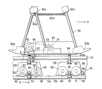
As shown in Figs. 1 and 2, a golf cart system of the
present invention includes a track 10 and a cart 50 which runs
along the track 10. The detailed structure of the track 10
will be described with reference to Fig. 2 which shows a
cross-sectional configuration thereof. The width of a track
portion exposed above the ground (grass surface) G is very
narrow and therefore there is little chance of a golf ball
hitting against the track 10 even if the track 10 is embedded
in the fairway of a golf course. This makes it possible to
install the golf cart system of the present invention on the
fairway of the golf course. The track 10 comprises a
generally horizontally extending bottom wall 12, two opposed
side walls 11 each generally vertically extending from the
bottom wall 12, two top walls 13 each extending from the upper
end of each side wall 11 toward the center of the track 10. A
slot or top groove 14 is defined between the top walls 13, and
a bottom groove 12b is defined between inner surfaces 12a of
the bottom wall 12. It is preferable to mount, on the
- 7 -
129~919
external surfaces of the top walls 13, covers 15 of suitable
elastic material such as rubber or artificial turf to cover
the top groove 14. The provision of the groove covers 15
makes it possible to prevent irregular bonding of golf balls
if they should accidentally hit the track 10 and also prevents
the entry of dirt or other debris such a dead leaves into the
track 10. The groove covers 15 are usually in closed
condition but are opened by posts 56 of the cart 50 as shown
in Fig. 2 when the cart 50 moves along the track 10. In order
to keep the top groove 14 surely closed by the covers 15, it
is preferable to differentiate the length of covers 15
projecting from right and left sides of the groove 14 and also
to lay the longer one on the shorter one as shown in
Fig. 5(a). This makes it possible to surely prevent the entry
of dirt or other debris into the track 10, since the longer
cover which is liable to sag is always firmly supported by the
shorter cover which is stiff and does not easily bend. On the
contrary, if the length of both covers 15 is equalized as
shown in Fig. 5(b), both covers 15 are liable to sag and a gap
C through which the debris will be entered into the track 10
is formed therebetween.
The cart 50 has a base frame 50a on which supporting
beds 50b and pillows 50c for supporting golf bags and other
golf equipment are mounted via pipe frames 50d. The cart 50
shown is designed for carrying only golf equipment, however,
i other types of carts for passengers or for both passengers and
golf equipment may be designed. The base frame 50a also
- 8 -
z9~9~9
supports thereon a power source such as an electric motor (or
a small internal combustion engine) 51 for driving the cart 50
and an intermediate pulley (or sprocket) 52. A belt (or
- chain) 54 is wound around the intermediate pulley 52 and a
pulley 53 secured to the output shaft of the motor 51. All
the components are concealed by a cover 55. Supportlng posts
56 extend vertically and downwardly from the under side of the
base frame 50a through the top groove 14 into the interior of
the track 10 as best shown in Figs. 1 and 2. A wheel
supporting frame 58 is mounted to each post 56 via a pin 57
(Fig. 2). Each wheel supporting frame 58 supports driving
wheels 59, first anti-rolling rollers 60 and second anti-
rolling rollers 61. The driving wheels 59 are rotatably
mounted on the frame 58 via bearings 65. A pulley (or
sprocket) 63 is secured to each axle shaft 62 of the driving
wheels 65 and a belt (or chain) 57 is wound around the pulleys
63 and the intermediate pulley 52. Thus, the power of the
motor 51 is transmitted to the driving wheels 59 via the belt
54, intermediate pulley 52, belt 57 and pulleys 63 so that the
driving wheels 59 can run on the inner surfaces (i.e. running
surfaces 12a) formed on the bottom wall 12 to drive the cart
50 forward as shown by an arrow A. It is preferable to mount
guiding wheels 64 on the front wheel supporting frame 58 for
guiding the cart 50 along the track 10.
Then, the mutual action between the track 10 and the
driving wheels 59, first anti-rolling rollers 60 and second
anti-rolling rollers 61 will be described with reference to
- 129~9~9
Fig. 2. The driving wheels 59 run on the inner surfaces 12a
of the bottom wall 12 of the track 10. Each of the inner
surfaces 12a of the bottom surface 12 is preferable to be
slightly inclined at an angle ~ (e.g. l - 2) so that the
rainwater entered into the track 10 flows to the bottom groove
12b. The first anti-rolling rollers 60 run on the inner
surfaces lla of the side walls 11. The first anti-rolling
rollers 60 can be so arranged that they always lightly contact
with the inner walls lla of the side walls 11 or they spring
urged against the inner walls lla to prevent the rolling
motion of the cart 50. In the embodiment shown, four first
anti-rolling rollers 60 are mounted on the wheel supporting
frame 58 at the opposite sides thereof. However, the number
and the position of the first anti-rolling rollers 60 to be
mounted can be properly determined. The second anti-rolling
rollers 61 are also mounted on the wheel supporting frame 58
at the under side thereof on the extention of the posts 56 and
arranged within the bottom groove 12b of the bottom wall 12.
When single second anti-rolling rollers 61 is mounted on each
wheel supporting frame 58, the diameter of the roller 61 is
formed slightly smaller than the width of the bottom groove
12b so as to contact either side wall of the bottom groove 12b
when the cart 50 tends to roll in either direction. The
number and the mounting position of the second anti-rolling
rollers 61 can be also properly determined.
Then a second embodiment of the present invention will
be described with reference to Figs. 3 and 4. A first
-- 10 --
`-`` 129~919
difference in the golf cart system of the second embodiment
from the first embodiment is that it is provided with anti-
pitching rollers 66 in addition to the first and second anti-
rolling rollers 60, 61. The anti-pitching rollers 66 prevent
the pitching motion of the cart 50 when it travels ups and
downs of a golf course. The anti-pitching rollers 66 are
especially useful for a golf cart system which is installed in
a golf course abundant in ups and downs. The anti-pitching
rollers 66 are mounted on the top of the wheel supporting
frame 58 and are adapted to run on the inner surfaces 13a of
the top walls 13. It is preferable to provide a slight gap
between the rollers 66 and the inner surfaces 13a of the top
walls 13 or to slightly urge the rollers 66 against the inner
surfaces 13a so as to prevent a generation of excessive
friction therebetween.
A second difference in the golf cart system of the
second embodiment from the first embodiment is that each wheel
supporting frame 58 is provided with two second anti-rolling
rollers 61 as shown in Fig. 6. The two rollers 61 can be
mounted on opposite ends of a lever 70 pivotably mounted on
the wheel supporting frame 58. A spring 72 is wound around a
pivotal shaft 71 of the lever 70 to rotate the lever 70 in one
direction (e.g. a direction shown by an arrow B) and to urge
the rollers 61 against the side walls of the bottom groove 12b
of the bottom wall 12.
In the tracks 10 shown in Figs. 2 and 4, the inner
surfaces 12a of the bottom wall 12 are provided with an
29~9~9
inclination angle d~ and the inner surfaces 13a of the top
walls 13 are provided with an inclination angle ~. However,
these inner surfaces 12a, 13a can be horizontally formed as
shown in Fig. 5(a).
Fig. 7 shows modifications of the driving wheels 59
around which an elastic flat belt 73 or V-belts 73' are wound
to increase the contacting area between the driving wheels 59
and the inner surfaces 12a of the bottom wall 12 and therefore
to decrease the slip therebetween. The flat belt 73,
preferably a cogged belt, is suitable for driving wheels of
the straight cylinder as shown in Fig. 7(a). The V-belts 73'
are suitable for driving wheels of tapered cylinder as shown
in Fig. 7(b).
According to the golf cart of the present invention,
since the width of the track exposed above the ground is very
narrow, there is less chance a golf ball hitting against the
; track. Even if a golf ball should happen to accidentally hit
the exposed track portion, the ball will bound similarly as
when hitting natural grass if the exposed track portion is
covered by elastic members such as artificial turf. This
makes it possible to install the golf cart system of the
present invention on the fairway of a golf course.
In addition, the rollinq motion of the cart is
effectively prevented by the first and second anti-rolling
rollers. Especially, the provision of the second anti-rolling
rollers enables to effectively prevent the rolling motion of
the cart, since they are positioned most away from the center
-12 -
Z9~919
of gravity of the cart and can generate a large anti-rolling
moment. Furthermore, since the first and second rollers do
not act to cause an excessive friction load between the
driving wheels and their running surfaces of the track, it is
able to reduce the consumption of electric power or gasoline
used by the power source and thus to increase the travelling
distance of the cart per battery charge or tank of gasoline.
The pitching motion of the cart is also effectively
prevented by the anti-pitching rollers. Thus the provision of
the anti-pitching rollers makes it possible to install the
golf cart system in a golf course abundant in ups and downs.
: --13--