Note: Descriptions are shown in the official language in which they were submitted.
--1--
M2T~O~ A~D APPARATnS FDR DETER~ G
ARTIC~LATORY PARAMETERS FROM SPEECS DATA
~ACX~R~ND OE' TOE IN~EMTION
FieLd of thQ I-~VQ~tLQn
The present invention relates to speech processing and
analysis and more particularly to a method and apparatus for
determining the presence and status o~ predefined
articulation parameters used in generating speech data.
The invention further relates to a system for displaying a
sectional view of anatomical changes occurring during the
speech process, based on variations in the articulatory
parameters.
Bak~LQund o~ the A~t
The art of creating proper speech in a given language
is perhaps the most complex and difficult- of learned
behaviors or tasks undertaken. How to speak and understand
speech occupies a large part of every child's education,
whether scbooled or not, because speech is such an important
aspect of effective communication.
However, many individuals suffer from physical or
mental impairments or impediments which make it more
difficult than usual to acquire and maintain "good" speaking
skills. Some individuals face re-learning speech skills
lost as a result of trauma. Others must acquire a new
language, which requires learning new skills that often
conflict with already-established speech patterns. If any
of these individuals cannot acquire the ability to more
effectively communicate, they may experience serious
difficulty functioning in social, work, or educational
[3152MPA.K17]
:~3~
--2--
situations. Often speech problems reinforce class
distinctions or prejudices, and also have grave economic
consequences.
It is, therefore, important to be able to assis~ many
individuals in acquiring proper speech skills beyond the
typical scholastic approach. It is also important to
accomplish speech training in the most efficient or
effective manner possible. Efficiency is important because
frustration and boredom with training or therapy regimes can
inhibit the learning process. In a sense, progress or
success depends on the level of frustration. This holds
true for all individuals from inherently inattentive or
active children, to overly anxious adults.
However, current speech therapy or training tends to
rely on techniques that are either laborious, uninvolving,
or incomprehensible to the student. One primary training
technique is the use of static pictures or representations
of the exterior of the vocal tract to show vocalization of
various sounds or phonemes. Unfortunately, students have
difficulty relating such views with complex internal (and
unseen) anatomical manipulations required for speech. This
lack of direct correlation between muscular motion or
control and sound output makes it difficult to effectively
alter speech patterns.
Constant repetitive exercise with a therapist can help
but still fails to overcome the correlation problem. A
trained therapist relies on subjective and laborious
clinical observations of the trainee or student to formulate
an explanation of what the student is doing incorrectly, and
what needs changing. Aside from the problem of boredom for
~3152MPA.K17]
--3--
the patient or subject, direct correlation between generated
speech or sound and vocal tract manipulation is not
achieved.
A variety of complex signal processing and spectral
display devices have also been used by therapists to
establish or record spectral patterns Eor use as
articulation indicators. Unfortunately, spectral displays
are generally so complex and signal analysis approaches
require such mastery, that the subject receives no useful
~eedback or information.
Alternate approaches include the use of computerized
spectral templates or look up tables to which speech data is
compared to determine its closest fit and, therefore, the
probable articulation process employed. Such approaches,
however, are speaker dependant and frequently fail to
correctly relate the predetermined, stored data with the
speech uttered by a subject.
It is believed that people would improve or alter their
speech easier or more effectively if they had a better
understanding of both what an ideal articulatory process
should be as well as what they are apparently doing
incorrectly when they utter speech. That is, speech
training can be far more effective when the subject sees a
direct correlation between sounds generated and the physical
processes required. For this and other reasons, such as
development of speech entry systems, there has been and
continues to be a significant amount of research into
understanding the speech process.
[3152MPA.K17]
~3~
Much of this research has sought to establish and
quantify articulatory parameters for human speech which
could be used to generally improve speech therapy and
training techniques. Several signal processing techniques
such as linear predictive coding and formant tracking have
been developed as a result of articulation research.
The linear predictive coding (LPC) approach utilizes an
idealized model of a vocal tract and computations of area
functions at discrete points along the model to predict
anatomical changes required for generating various sounds.
However, the idealized model does not correspond with actual
vocal anatomy~ but is a mathematical construct that can
produce anomalous operating characteristics. The LPC
approach also fails to account for factors such as the
variation of formant bandwidth from speaker to speaker and
nasality. Therefore, this approach has proven unreliable in
estimating articulator activity even for a single speaker.
The formant tracking approach determines articulation
parameters based on the position of formants derived from
spectral data. However, there are reliability and
reproducibility problems associated with tracking formants
in continuous speech data. For example, it is extremely
difficult to reliably find formant peaks. In manual formant
tracking, the marking of formant tracks i5 often based on
subjective criteria which also affects reproducibility. At
present, formant tracking has proven to be too unreliable to
support consistent and accurate estimation of articulatory
features.
All of these and other problems have limited the
~0 progress of incorporating automatic signal processing into
[3152MPA.K17]
~L3d~2~
--5--
speech training and therapy. What is needed is a method and
apparatus for determining the status of articulatory
parameters that operate substantially in real time. It is
also desirable to have a method of determining the status of
articulatory parameters that provides dynamic visual
feedback, is not speaker dependent, and can accommodate a
large variety of subjects.
S~M~A~Y
In view of the above shortComings and problems in the
art of speech processing and its application to therapy, one
purpose of the present invention is to provide a method and
apparatus for determining ~he values of a predefined set oE
articulatory parameters in audio speech data.
Another purpose of the present invention is to provide
a speaker-independent method and apparatus for determining,
from continuous oral speech, the values of a predetermined
set of articulatory parameters which represent the
configuration of the vocal anatomy that produces the speech.
An advantage o the present invention is that it
provides a method and apparatus for ascertaining the values
of a series of articulatory parameters descriptive of
anatomy which produces human speech.
Another advantage of the present invention is that it
provides a method of accurateLy interpreting articulatory
para~eters for representing articulation of individual
phonemes.
Yet another purpose of the present invention is to
provide a method of evaluating a set of articulatory
parameters which allows visual representation of anatomical
[3152MPA.R17]
. . .
~31;~2~7
features of the vocal tract in response to changes in the
parameter statusO
These and other objects, purposes, and advantages of
the present invention are realized in a method and system
for determining the values of articulatory parameters that
represent articulation tract configuration during the
production of oral speech. In this regard, "articulatory
parameters" are parameters which, collectively, describe a
cross-sectional representation of vocal tract anatomy. Each
parameter corresponds to a respective portion or sector of
the anatomical representation, and the value of the
parameter signifies the displacement or instanteous location
of the represented anatomical portion with respect to an
initial location. In the theory of the invention described
herein, the speech produced by the represented vocal anatomy
is composed of a continuous sequence of "spectra". The
spectra of interest in understanding the preferred
embodiments of the invention are associated with phonemes,
which are taken to be the most basic, distinguishable units
of speech in a given language.
The present invention includes a method for
determining, from speech, the values of articulatory
parameters indicative of the configuration of an
articulatory tract producing such speech. The method
includes the steps of establishing a plurality of speech
phoneme classes, each including a plurality of speech
phonemes sharing similar spectral and articulatory
characteristics, providing digital speech data, monitoring
energy levels in the digital speech data, and selecting
segments of the da~a for analysis based on predefined
[3152MPA.K17]
~L3~
magnitude changes in data energy. The selected segments are
processed by an FFT algorithm, preferably after filtering
and application of a windowing algorithm, to provide digital
spectral data segments. The log of the magnitude o~ the
spectral segments is conditioned to remove signal variations
below a preselected signal magnitude, which eliminates noise
and ambiguous information.
The resultant spectral data segments are multiplied
with a class distinction or selection matrix multiplier to
provide a vectorial representation of the probability of
which class of a plurality of predefined spectral classes
the sound being received falls into. At the same time, the
spectral data segments are applied to a plurality of class
matrix multipliers which provide vectorial outputs
representative of predetermined articulatory parameter
values~ The class distinction vector information is directed
to a plurality of multipliers for combination with the
output of the class matrix multipliers so that a weighted
average of class vectors is generated for a given sound. A
summation means is employed to combine the resultant class
vectors to form a single feature vector whose elements are
the articulatory parameter values for the speech data being
processed.
The method of the present invention can further
comprise the steps of generating an image representative of
a mid-sagital view of human vocal tract anatomyl associating
the articulatory parameters with corresponding anatomical
points on this image and altering the image according to
variations in the articulatory parameter values. This image
[3152MPA.K17]
- :13~ 7
--8--
processing can be accomlished in real time with direct or
pre-recorded speech data to assist in speech therapy.
The system for deriving the values of a set of
articulatory parameters from speech data according to the
S invention is more particularly summarized as a sampling
circuit for sampling speech data at a predetermined sampling
rate and for selecting data segments of said speech data of
predetermined length at predetermined sampling intervals
according to particular changes in energy in the speech
data. A transformation processor connected in series with
the sampling means receives the selected data segments and
transforms them from time-varying amplitude data into
spectral data segments. A first mapping means connected to
the transformation processor associates spectral data in
each of the spectral data segments with one or more of a
plurality of predefined spectral classes so as to generate a
weight for the probability that said segments correspond to
spectra within each of the classes. A second mapping
means is connected in series with the transformation
processor and in parallel with the first mapping means for
transforming spectral data in each of the spectral data
segments into a set of articulatory parameter values for
each of the plurality of classes. A combination means is
connected to the first and second mapping means for
combining the weight for the probability of a given class
with the mapping into the articulatory parameter values for
each class so as to generate a single, weighted N parameter
output, whose elements are the articulatory parameters for
the speech data being processed.
[3152MPA.K17]
)Z~i7
The sampling circui~ embraces a digitizing means for
sampling speech data at a predetermined sampling rate and
for forming digital speech data therefrom, an energy
monitoring means for monitoring changes in energy in the
sampled speech data, and a segment selection means connected
to the energy monitoring means for selecting segments of the
digital speech data of predetermined length at predetermined
sampling intervals according to desired changes in energy.
The energy monitor means includes a scaling means for
converting digital speech data to a logarithmic amplitude
scale, a delay line in series with the scaling means for
applying a predetermined delay to received logarithmic
speech data, and summation means connected to an output of
the delay means and the scaling means for arithmetically
combining speech data with delayed speech data. A trigger
means connected between the summation means and segment
selection means provides a selection signal to the selection
means in response to an increase in the energy of the data
segments for predetermined numbers of sampling periods.
The first mapping means comprises first transform
matrix multiplication means for multiplying spectral data
segments by a predefined class distinction matrix~ A vector
normalization means receives the first mapping means output
and generates a normalized ctass vector therefrom. The
second mapping means comprises second matrix multiplication
means for multiplying the spectral data segmen~s by a
plurality of predefined class matrixes.
In addition, where desired, the articulatory parameter
values are visually displayed as part of an animated mid-
sagittal, anatomical representation on a visual display
3152MPA.K17]
267
--10--
means connected to an output of the combination means. Thedisplay means comprises graphics display means for
displaying a predefined graphic pattern in the form of a
human articulatory tract on a visual screen, and animation
means for altering the graphic pattern in response to
changes in the articulatory parameters. The display is
combined with real time or recorded speech data to form an
improved speech therapy and training apparatus.
BRIEF D~SCRIPTION OF T~E DRA~INGS
The novel features of the present invention may be
better understood from the accompanying description when
taken in conjunction with the accompanying drawings in which
like characters refer to like parts and in which:
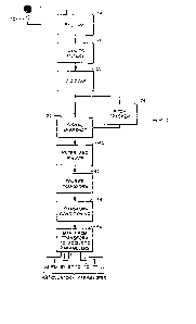
Figure 1 illustrates a me~hod for determining and
displaying articulatory parameters from audio speech data
according to the principles of the present invention;
Figure 2 illustrates a speech system for determining
and displaying articulatory parameters operating according
to the method of Figure l;
Figure 3 illustrates a typical input stage used for
digitizing and filtering speech in the system of Figure l;
Figure 4 presents a more detailed schematic o~ the
pitch tracker and signal snapshot elements of Figure l;
Figure 5 shows a more detailed view of the signal
filtering, window, Fourier Transform, and conditioning
elements and steps employed in the apparatus of Figure l;
Figure 6 illustrates a schematic of the mapping
elements for articulatory parameters employed in the
apparatus of Figure 1 and class selection and parameter
determination steps;
[3152MPA.K17]
13~30Z~ '~
--11--
Figure 7 illustrates a display for the selected
articulation parameters; and
Figure 8 illustrates a speech therapy system employing
the present invention.
S D~TAILED D~SCRIP~ION OF A P~FER~D E~ODIME~
The present invention allows the identification ox
determination of the values of a series of predefined
articulatory parameters from audio speech data. This is
accomplished by converting speech data into analog signals
which are pre-conditioned or Eiltered and then digitized.
Variations in the energy level of the digitized signals are
monitored through pitch tracking elements and used to select
segments of ~he digitized signals for processing based on
predetermined tracking criteria. Segments composed of a
predetermined number of data samples are selected from the
digital signals, filtered to enhance high frequency
components, and subjected to a Fast Fourier Transformation
(F~T) algorithm to generate a frequency domain image of the
speech signal.
The resulting frequency domain samples are further
conditioned to minimize the impact of variations and noise
and then mapped according to a series of predetermined
relationships into an array of desired articulatory
parameters. The mapping of spectral samples into
articulatory parameters utilizes multiplication of the data
by a set of matrixes. Each matrix represents an established
class of speech phonemes which share similar spectral and
articulatory characteristics. It is asserted that the
phonemes in a class, when uttered, can be rendered into like
spectral patterns and are produced b~ corresponding
[3152MPA.K17~
:l~O~Z'~7
-12-
configurations of the articulatory tract. The matrixes are
established based upon a correspondence between known
spectra and articulatory parameters through use of a
phonemic correlation technique.
The steps used in the method of the present invention
are illustrated in flow chart form in Figure 1. An
articulatory parameter value determination apparatus 10 for
implementing these steps is illustrated in schematic forrn in
Figure 2.
In Figure 1, oral speech is first converted into a
signal which is subsequently amplified, filtered and
frequency compensated before being digitized for final
processing to produce the desired output. This conversion
is implemented, as shown in Figure 2, by using a microphone
12, or similar audio signal pickup device for detecting oral
speech and converting it to signal representing amplitude
and frequency variations in the detected speech.
The microphone signal is subsequently processed by a
pre-amplifier 14 to boost the general signal level.
Alternatively, other components such as band equalizers (not
shown) can be employed as desired to alter the amplitude or
frequency characteristics of the input signal. Pre-
amplifier 14 comprises one of several commercially available
amplifier or pre-amplifier circuits used for increasing
signal levels. An exemplary pre-amplifier 1~ circuit is an
amplifier produced by the Radio Shack division of the Tandy
Corporation of Fort Worth Texas under the designation of
Realistic Amplifier model number MPA-20.
Before being digitized, the output of the pre-amplifier
14 is filtered to provide high frequency boostingl remove DC
[3152MPA.K17]
-13-
bias, and minimize aliasing. Providing high-~requency boost
across the sampled audio band provides a more nearly flat
spectrum and compensates for the fall off of about 6 d~ per
octave, typically encountered in the speech spectrum. The
boost results in speech formant peaks which exhibit roughly
equal amplitude across the spectrum rather than falling with
increasing frequency. Thus spectral peaks generated by
fricatives with high frequency content will have energy
comparable to the peaks produced by low frequency vowels.
Therefore, less dynamic range will be required in any
subsequent digitizing step to effectively capture the signal
characteristics of interest.
As shown in more detail in the schematic diagram of
Figure 3, a capacitor Cl and two resistors Rl and R2 form a
high frequency boost circuit as well as provide impedance
matching ~or the following circuit elements. The capacitor
Cl also provides a DC filter The filte~ functions to
remove DC biasing which otherwise degrades FFT performance
in later processing steps. The preferred boost circuit is
configured to provide a high-frequency boost of
approximately 6 dB per octave between about 300 and 2,000 Hz
which is the primary spectral range of interest in
processing speech data. An anti-aliasing filter 1~ is
connected in series with the boost circuitry and provides a
sharp roll-off in frequency above 5 kHz. An exemplary filter
18 is a 5 kHz low-pass filter available from TTE, Inc. of
Santa Monica, California under the designation number TTE
J71G~ Two resistors, R3 and R4, provide impedance matching
between the outpu~ of the anti-aliasing filter 18 and a
digitizer 20. These resistors also adjust the signal input
[3152MPA.K17]
13~Q~7
level for the digitizer 20. A digitizer 20 samples the
output of the anti-aliasing filter 18 and generates a
corresponding digital speech signal. The digitized signal
comprises a series of multi-bit values or data words
representing the relative magnitude of the speech signal at
periodic sampling times. Such digitizers are known. An
exemplary digitizer which has been found useful in
implementing the preferred embodiment i5 the Audio Digitizer
manufactured by Impulse, Inc. of Minneapolis, Minnesota.
In the preferred embodiment, the digitizer 20 is
configured to sample the speech signal at an 11 Kilohertz
sampling rate and generate 8 bit data values for each
sample. A signal sampling rate of at least twice the
highest frequency of interest is used. An 8 bit data word
length is large enough to maintain significant spectral
detail during digitizing and at the same time provide
compatibility with a large number of exlsting computers for
implementing the remainder of the present processing
method.
From the point where the speech signal is digitized,
digital computational techniques and structures implement
all of the functions yet to be described. Those skilled in
the art will be aware that any function of the remainder of
the invention implemented in the form of a digital process,
executable by a digital computer, has a corresponding
analog implementation.
As shown in Figure 1, the digitized speech signals are
monitored to determine variations in energy content. This
information is used to select data segments comprising a
[3152MPA.K17~
~3~U~
--15--
series of samples for further processing to determine
articulation parameters.
As shown in Figure 2, digital speech signals or samples
are provided by the digitizer 20 to a signal snapshot
element 22 which selects segments of the digitized signal
for further processing. The determination as to which
portion or portions of the digitized speech signal are
selected for further processing is made by a pitch tracker
24. The pitch tracker detects sudden increases in high
frequency energy.
The operation and structure of the pitch tracker 24 and
the signal snapshot element 22 are shown in yreater detail
in Figure 4. In Figure 4, a digital signal enters the first
stage of the pitch tracker 24 which comprises a full wave
rectifier 26. The rectifier 26 generates an output signal
which is the absolute value of the digital speech signal.
The absolute value indicates changes in the relative energy
of the digital signal.
The next stage of the pitch tracker 24 is a smoothing
~0 filter 28 which smoothes the output of the rectifier 26 to a
single smooth pulse so as to reduce spurious oscillations or
oscillating bursts of energy resulting from pitch pulses.
The filter 28 chosen for the preferred embodiment operates
according to a relationship defined by:
Yn = (15/16)Yn-1 + Xn/16 (Eq- 1)
where Yn is the output signal and Xn the input signal. This
relationship is found to provide very good results in
smoothing formant oscillations. After the filter 28, the
[3152MPA.K17]
-16-
digital speech signal is processed by a logarithmic
converter 30 which changes the linear scale of the digital
signal to a logarithmic scale. Converting to a logarithmic
scale allows subsequent processing to be independent of
absolute signal level and allows the pitch tracker 24 to
operate over a wide range oE input signal levels. This is
important in speech analysis where there is a significant
dynamic range.
The output of the log converter 30 is used to drive a
trigger logic unit 36 which is used to gate segments from
the digital sample input for subsequent processing. The
trigger logic unit 36 uses a difference between the log
converter 30 and a second input to determine trigger status
or activation. The activation of the trigger conforms to
certain changes in short term energy level for the digital
signal.
In the method of the present invention, wideband
spectral data is being used for procPssing because fine
spectral resolution given by long term analysis times is not
needed, can often be misleading, and smoothes out short term
changes that may contain significant feature information.
With this in mind, it is desirable to process the digitized
speech approximately 32 samples at a time which allows
implementation using a very efficient and fast FFT circuit.
Additional spectral detail is not needed using the method of
the present invention and processing larger segments of data
requires additional FFT steps with a resultant loss of
speed.
The spacing bet~een segments, or selection of each
group of 32 samples, sets an outside limit for trigger
[3152MPA.K17]
13~6i~
timing. There is a limit to how fast the vocal tract can
move so no additional information is gained by continuously
selecting segments. Only the selection of one segment per
pitch period is desired. Further, human pitch is unlikely
S to exceed 458 Hz which at the sampling rate chosen above,
corresponds to a separation between pitch pulses of 24
samples. Therefore, a minimum spacing of 24 samples is
established between selected segments.
At the same time, it is not desirable to sample too
infrequently since relevant data may be missed. Since the
lowest pitch is likely to be on the order of 49 Hz, a
maximum delay of 224 samples is used. This assures that
information from unvoiced sounds, for which triggering is
erratic, is not discarded.
The triggering or selection decision is made on the
basis that the energy in the segments must be increasing for
a predetermined period. To check the desired trigger
criteria, a signal from the log converter 30 is subjected to
a delay circuit 32 before being subtracted in the
subtraction element 34. The subtraction of a delayed signal
from the converter 30 output produces a result ~n which is
indicative of the variation in energy in the digital signal
over the delay period.
~ f ~n is less than or equal to zero then the signal
energy is dropping or constant over this sample period. In
this situation no new samples are desired and the trigger
logic does not generate a trigger output until 22~ sample
time periods have passed since a previous segment selection.
However r if is greater than zero then the energy level is
[3152MPA.K17]
~3~Z~
-18-
increasing and additional segment selection and trigger
criteria are used.
In the present invention, a segment is not selected
unless the energy level has been rising for at least 4
sample periods. As long as the energy does not rise for
more than three sample periods segments are not selected
until the 224 sample period is reached. This condition
exists where the signal energy is still rising or is not
indicative of a true pitch period.
If the energy level has risen for exactly four sample
periods, then segments are not selected unless it has been
at least 24 sample periods since the last selection. It is
undesirable, as previously discussed, to trigger too soon.
The preferred embodiment of the trigger logic i5 illustrated
by the digital process illustrated in the following pseudo
code listing:
~3152MPA.K17]
--19--
TA~LB 1
111 If ~n~0 ~ * energy not rising * /
112 then
113 rise_time = 0
114 time_since_trigger = time_since_trigger + 1
115 If ~n>0 / * energy rising * /
116 then
~'`,'! 117 rise_time = rise_time +1/
118 If rise_time ~ 4
119 or (rise_time = 4 AND time_since_trigger ~ 24)
120 or (rise_time c 4 AND time_since_trigger <224)
121 then
122 time_since_trigger = time_since_trigger + 1
15 123 / * energy continues to rise after trigger is
trying * /
124 / * to trigger too soon, or is starting to rise ~ /
125 else
126 time_since_trigger = 0
20 127 TRIGGER
In Table I, ~n = Zn ~ Zn-lO~ since Z indicates the
energy level of the speech signal, ~n measures energy
difference over 10 samples (Zn - Zn-lO)- If the speech
signal is digitized at a digitizing rate of llKHz, 10
samples is, approximately, 0.91 milliseconds. In code line
119, the delay of 24 samples represents a pitch of 458Hz,
well above the pitch range of most children. In line 120,
the 224 sample delay represents a pitch of 49 Hz, which is
[3152MPA.K17]
3~Q(~Z~i7
-20-
below the expected lowest pitch frequency uttered by an
adult male.
Once the trigger logic 36 determines that a segment s
to be selected, a pulse is provided to a sample selector
and a segment of 32 samples is passed to the next stage of
processing.
Returning now to Figure 1, we see that the selected
digital samples are next processed in a filter and windowing
step to prepare them for a subsequent FFT processing step.
As shown in Figure 2, this is implemented in a preferred
embodiment by transferring digital speech samples through a
filter and window circuit 40, which is shown in more detail
in Figure 5. This is followed by some post transformation
signal conditioning in the conditioning circuit 44, also
shown in more detail in Figure 5.
As shown in Figure 5, the data samples are processed
by a filter ~6 which provides a high frequen~y boost
transEer function. This ensures that the FFT processing,
which is done with limited precision arithmetic, will not
lose high frequency information in quantizatiOn noise. The
preferred filter function employed is defined by:
Yn - Xn ~ Xn-l (Eq. 2)
where Y is an output signal, X is an input signal, and,
typically, 0.5<~ <0.7.
The technique of windowing is well known in the arts of
signal and speech processing. There are a variety of window
"functions" that are multiplied times the signal sample
values to establish a desired window. A general discourse
3152MPA.K17~
il~3~ 7
-21-
on their properties is found in an article entitled "On the
~se of Windows for Harmonic Analysis with the Discrete
Fourier Transform" by Frederick J. Harris, PROC. IEEE, Vol.
66, No. 1, January 1978.
However, some window functions such as a strict
"rectangular" window create unwanted perturbations in the
spectrum during the windowing process. Therefore, to
eliminate such problems, a raised cosine window function is
used in the preferred embodiment. The preferred windowing
function is defined by the relationship:
Wn = 0.5 - 0.49 Cos(~tfl6)n, for n = 0...31 (Eq. 3)
At this point the resultant digital data samples are
processed by a 32 point Fourier Transformation algorithm in
a Fourier Transformation processing element 42. An
exemplary algorithm is:
~31
Zk = ~. Yn~e -j(2 ~ /32)nk, for k = 0.... 15 (EgO 4a)
n=0
where ~Zk~is the output signal and~Yn'} is the input signal,
andO
Yn = Yn ~ Wnr for n = 0...31 (Eq. 4b)
This algorithm has been found to be very useful for
implementation of high speed processing in real time~ In
the preferred embodiment, an equivalent fast fourier
[3152MPA.K17]
transform (FFT) algorithm is used to accomplish the result
of equation (4a). The FFT algorithm can operate on the
digital data samples as a program routine where the samples
are transferred into a computer for anaysis.
The FFT processing element 42 of the preferred
embodiment is configured to provide spectral data segmen~s
in the form of a spectral vector, Zkr for each data segment
input. That is, each time varying input signal is converted
into an array of values which represent the relative
frequency composition of the input signal across
predetermined frequency ranges. In the preferred
embodiment, the FFT element 42 produces a spectral vector
~Zk~ having 16 values each of which represents a specific
frequency range, with vector indices of 0 to 15. For
example the values of vector ~Zk} in the first range or
index location, 0, represent frequency compositions for the
input signal between 0 and about 345 Hertz whereas spectral
indices 2 through 4 represent frequencies of about 687 to
1375 Hertz.
As seen in Figure 1, the output from the FFT element 42
is conditioned before final processing to account for
processin~ variations and noise. This is accomplished in
the apparatus of Figure 2, by transferring the output, ~2k~'
of the FFT element 42 to a transform conditioning element 44
which is shown in further detail in Figure 5.
In Figure 5, the FFT element output ~Zk} is transferred
into a log converter 50. It has been found that human
speech is interpreted in a non-linear fashion by the human
mind and that a logarithmic scale more accurately reflects
the relationship between any given sound spectrum and its
[3152MPA.K171
-23-
mental interpretation. Therefore, the present method was
developed using a logarithmic relationship in order to more
accurately reflect and determine proper weighting and
interpretation of sounds.
The Fast Fourier Transformation process for 32 samples
of real data generates 1~ complex samples. Therefore, the
log converter 50 is configured to generate the log of the
magnitude of the FFT output ~Zk} or
2'k = log2 [mag (Zk)~ (Eq. 5)
It is assumed, in the practice of the invention, that,
in any electronic or digital processing technique, there
exist signals that are below the discrimination and general
noise level of conversion or processing and detection
circuitry. It is also assumed that, owing to the nature of
later processing steps, many signals below a certain
predefined level will not provide accurate or useful
information for the processing. That is, the limited amount
of useful information in these signals gives rise to
ambiguities and uncertainties that make further processing
undesirable. Therefore, spectral signals below these
predefined levels are discarded using a threshold
comparator.
The art of speech processing has assumed that the
threshold for signal noise is very low and processing should
incorporate as much of the signal as possible. Where there
are errors or ambiguities, it has generally been assumed
that more information needs to be collected from a speech
signal to complete or improve processing. It is an
~3152MPA.K17]
3~i2
-24-
advantage of the present invention that these assumptions
regarding speech processing are not employedO
Instead, it has been found through the diligent efforts
of the invention that the speech determination or
interpretation system of the human mind does not and cannot
assimilate all of the data present in audio signals. That
is, the entire audio signal is not used to interpret speech.
From this it can be seen that in any electronic processing
of the signal a higher threshold can be used to discard
material that is really extremely difficult and impossible
to accurately interpret. By setting a higher noise
threshold no useful information is lost if the electronic
system is operating under proper constructs. At the same
time, ambiguous or incomplete information (data) is removed
which actually improves the overall performance.
Returning to Figure 5, a signal spectrum conditioner 52
processes the log converter output si9nal~zlk~to establish a
minimum signal level useful for the method and apparatus of
the present inventionO An exemplary threshold or
discrimination relationship employed by the conditioner 52
is :
Z k = Z'k - (max ~Z'k} - N), for k = 0...15 ~EqO 6)
where ~Z"k~ is an output signal, ~Z~k~ is an input signal,
max Z k~ is the maximum value obtained by the signal
'k}' and N iS determined by the amount in
decibels to be retained.
Typically N iS chosen to retain between about 15 to 20
dB. Those skilled in the art are familiar with circuits or
[3152MPA.K17]
:13~2f~7
-25-
devices used to establish such a threshold relationship in
digital signals. As before, this relationship can also be
accomplished using software where the signal is transferred
into a digital computer.
Returning now to Figure 1, the conditioned samples
~Z~k~ are now mapped from transformed spectral data into a
series of predefined acoustic or articulatory parameters.
As shown in Figure 2, this is accomplished using a mapping
element 54 which provides a series of articulatory parameter
values for each discrete spectral sample input. An exemplary
apparatus for constructing the mapping element 54 is shown
in greater schematic detail in Figure 6.
In order to implement the method and apparatus of the
present invention and map spectral data into articulatory
parameters, the parameters to be detected and the method by
which they are associated with spectral patterns are first
established.
The method of the present invention employs commonly
accepted linguistic units known as "phonemes" to segment
speech data or spectra into discrete classes of similar
spectra which can be appropriately related to a specific set
of articulation parameters. The invention is based upon the
identification of approximately 24 basic phonemes which
occur in spoken data. It i9: actually the spectra which
characterize these 24 phonemes that are observed, but the
phonemes are useful as associative labels or markers for the
related spectra.
The phonemes used in formulating the mapping process
are listed below in Table II, along with an arbitrary
numerical assignment and a categorization as to type. It
[3152MPA.K17]
13~2~7
-26-
should be noted that only continuants, as opposed to
transitory events such as stops, etc., are present in Table
II. As is known, continuants exhibit spectral stability
over many milliseconds, which provides ample opportunity to
sample them. In Table II, no distinction is made between
voiced and unvoiced fricatives since vocal tract shapes
which produce them are essentially equivalent.
The continuants listed in Table II are set out in four
primary classes: vowels, fricatives, liquids, and nasals.
Also, glides and some special phonemes are allocated
processing definitions where desired. It is noted that the
present invention does not limit analysis and processing
exclusively to the list of Table II. Other phonemes can be
used to account for particular articulatory patterns that
arise frequently in certain types of speech or speech
therapy. In addition, the entire list need not be used,
although important articulation information will otherwise
be lost to the user. Those skilled in the art will realize
that the classes established by Table II are language
dependent.
[3152MPA.K17]
:13~ 7
TAOLE II
VQwels
as in as in as in
5 1 - /i/ (beet) 5 ~ /A/ (bat) 9 - /~/ (book)
2 - /I/ (bit) 6 - /a/ (bottle) 10 - /u/ (boot)
3 - /e/ (bait~ 7 - /O/ (caught) 11 - /&/ (but)
4 - /E/ (bet) 8 - /o/ (boat) 12 - /r/ (bird)
1 o _i/aU _dQ
as in as in
13 - /R/ (road) 14 - /L/ (little)
Fricatives
as in as in
15 - /s/ (sing, zing) 18 - /T/ (Thought, this)
16 - /S/ ~shove, measure) 19 - /h/ (he)
17 - /f~ (file, very)
Nasals
as in as in
20 - /m/ (mom) 22 - /N/ (sing)
21 - /n/ (no)
GLid~
as in as in
23 - /y/ (yet) 24 - /w/ (wet, when)
For purposes of illustration and implementing a
preferred embodiment, a series of eight articulation
parameters were chosen for correlation with the phonemes
~3152MPA.K17]
2~
-28-
listed in Table II. The parameters used in the invention to
describe the anatomical characteristics of the human vocal
tract are:
Jaw Opening (JO)
Lip ROunding (RO)
Tongue Center height (TC)
Tongue Back horizontal position (~X)
Tongue aack vertical position (B~)
Tongue Tip horizontal position (TX)
Tongue Tip vertical position (TY)
Lower Lip retraction (LL)
The title or designations for each of these parameters
refer to the anatomical location or element whose position
is described by that parameter and are easily understood by
those skilled in the artO The last parameter, LL is used to
describe the lower lip offset from the value specified by
Lip ROunding parameter which is needed for forming phonemes
such as /f/ and /v/.
Those skilled in the art will readily appreciate that
additional parameters, or alternate forms o designation,
can be assigned and correlated with the articulation of the
phonemes listed above. An example would be a parameter to
track tongue flattening or tensio~. However, using
additional parameters also requires additional processing
power and time which are tradeoff considerations for
specific applications.
The definitions or physical attributes for the above
parameters are determined by a careful analysis of
[3152MPA.K17]
~,3~ ";Z ~t7
-29-
information available in research publications, x-rays of
vocal tracts in operation, information from speech
therapists, and data samples taken in laboratory
measurements.
S Laboratory measurements can include spectral data
accrued over time by tracking known phonemes. That is,
well-identified phonemes ace monitored from known speech
sources and their spectra segregated to allow correlation of
the spectra with each associated phoneme. The spectral data
must be accumulated Erom a significant number of subjects
and a variety of speech types (male, female, female child,
male child), to provide a significantly speaker-independent
system.
The above information provides a data base of known
anatomical motion or muscle positions used to create sound
for forming specific phones or phonemes. This in turn
defines the position of various articulatory tract or
anatomical features and, therefore! the values for the
articulatory parameters. That is, by reviewing the above
data or information, specific values for the relative
position of a speaker's jaw, tongue tip, tongue center,
tongue back, etc., are established for specific sounds or
phonemes being formed. This means that a given anatomical
configuration is established ~or each phoneme in the above
table.
The articulatory parameters are expressed in terms of
position along a parameter axis which represents the
movement with respect to a pre-selected base or origin (0,0)
value. The actual coordinate values or base-coordinate
positions used in defining parameters are chosen to simplify
[3152MPA.K17]
-30-
computations and satisfy known physical limitations. ~or
example, the tongue tip cannot move higher than the roof of
the mouth, but the teeth can close farther together than
where they first touch since they can rest in an overlapping
position. The indexes for the articulation parameters are
set to prevent physical improbabilities and to use a
relative scale commensurate with the resolution of any
associated display systems, as discussed below. Those
skilled in the art will readily understand the process by
which selection of base-coordinates and scale are made and
will adjust these values to fit particular applications.
Using these known anatomical configurations or
patterns, each phoneme ph(n) Erom the list of 24 preferred
phonemes is assigned a representative feature vector,
f(n,p), having as its elements eight specific articulatory
parameter (p). The feature vector f~n,p) for a specific
value of n is a 1 by 8 vector containing individual elements
for each of the articulatory parameters listed above, which
can be conveniently expressed as:
f(n,p) = ~JO(n), RO(n), TC(n), BX(n),
BY(n), TX(n), TY(n), LL(n)]
However, those skilled in the art will understand that
alternate parameter sequences are possible within the
teachings of the present invention.
The next step is to define the relationship for
mapping measured spectra into the designated feature
vectors. This is made possible by recognizing that each
phoneme has one or more spectral patterns associated with it
[3152MPA.K17~
~3~Ui~
-31-
which can be treated as a substantial indicator or signature
for it. Therefore, the spectra or spectral distribution of
speech data can be directly mapped onto, or correlated with,
articulatory parameters through use of the phonemes to which
corresponding parameters are assigned. The method oE
the present invention employs a fea~ure map Eor mapping
spectral data into the articulatory parameters. Using this
feature map allows the spectrum information provided by the
FFT element 4~ to be interpreted to determine its
articulatory parameter composition. This is done by
generating linear transformation matrixes for classes of
phonemes. These class matrixes are multiplied by the FFT
output spectral data to generate a reasonable approximation
of the feature vector corresponding to the sound producing
the spectrum. The matrixes are developed using principles
of matrix derivation, multiplication, and transposition
understood in the mathematical arts. To date, speech
processing has not used this technique before to provide a
spectral mapping of wideband spectral information into
spectral or phoneme classes. The following derivation
explains the steps which must be taken to build a set of
~apping modalities (matrixes) necessary to understanding and
using the invention. This is done once in the laboratory,
rather in real time during the practice of the invention.
The preEerred phonemes are first grouped together into
classes according to spectral and articulatory similarity.
An exemplary grouping of phonemes into classes, based on
spectral and articulatory similarities for the phonemes
discussed above is:
[3152MPA.K17]
- l3r~ ,7
Class 0 sSTfh fricatives
Class 1 iIeEA front vowels
Class 2 AaO&ho low vowels
Class 3 o~uw back vowels
Class 4 Rr R's
Class 5 Ln L and nasals
It should be noted that phonemes such as /h/, /o/ and
/A/ each appear in two classes. This is because these are
"border line" cases and the classes can overlap.
~ sing the above Class grouping, the linear
transformation matrixes can be derived as follows:
For a given class C there is a set of phoneme feature
vectors:
f(n,p) : for p = 0...7 and n in Class C
and a set of measured spectra:
s(j,n,i) : for j = 0...15, n in Class C, and i = 0~..M~n)-l
where M(n) is the number of spectra representing class C.
A linear transformation matrix T, and a constant
vector, c, is required for transforming the measured
spectrum s(j,n,i~ into feature vectors. In this regard,
when T is multiplied times an observed spectrum, s, and
added to c, a reasonable approximation of the feature vector
f(n) that corresponds to the sound made in producing s is
generated. That iS9 for the spectrum s, representing
phoneme n, the expression:
[3152MPA.K17]
-33-
T * s(n) + c = f(n) (Eq. 7)
produces a close fit to the f(n) feature vector for the
phoneme ph(n).
Each row of the matrix T is independent of the others
which allows each element of the feature vector (such as
each parameter p) to be considered separately. Therefore,
for a given parameter p we have values of f(n) for each n in
C and a set of spectra s(j,n,i). What is needed is a 16
value vector t(j), where j = 0...15, that is one column of
the transformation matrix T, such that:
t * s(n,i) + c ~ f(n~ (Eq. 8)
for i = O...M(n)-l and all n in C, with the 16 values
corresponding to the spectral divisions or ranges provided
by the FFT processing.
The first element s(O,n,i) is almost always nearly zero
due to the removal of DC bias before FFT processing. The
value s(O,n,i) is deleted because it essentially represents
noise or energy at 0 Hertz. Therefore, the element s(O,n,i)
is replaced by a constant (e.g. 1), which has the effect of
replacing the first element in the vector t(j) with the
constant c, and equation(s) becomes, more simply:
t * s(n~i) ~ f(n) (Eq. 9)
for i = O...M(n)-l, all n in C.
E3152MPA.K17]
~3~
-34-
Rigorously, there is a vector t that minimizes the mean
square error (EC) between t * S(N,i) and f(n):
~ (n)-l 2
EC = ~ ~_ [t*s(n,i) - f(n)] (Eq- 10)
n in C i=0
~ ~n)-l ~ 15 -~2
EC = ~ 2 1 ~ t(j)s(j,n,i)] - f(n)~ (Eq. 11
n in C i=0 _ j=0
which becomes:
15 EC = ~ ~ [ ~ ~ A(j,k)
n i j=0 k=0
(Eq. 12
- 2f~n)~ f(n)
j=o
where. A(j,k) = t(j) s(j,n,i) t(k) s(k,n,i)
~(j) = t(j) s(j,n,i)
Standard calculus suggests that EC is a minimum when
the partial derivative of EC with respect to each t(j) is
zero. Performing the partial derivation and solving for t(j)
yields:
[3152MPA.K17~
L3~(~Zt~
-35-
t(j) = ~ S (m,j) F(m,p) (Eq. 20)
m=0
where S-l is the inverse of a symmetric matrix S and where S
and F are computed from the spectral data s(j,n,i) and the
desired feature vectors f(n,p) as follows:
M(n)-l
Stm,;) = ~~ s(j,n,i) s(m,n,i) (Eq. 21)
n in C i=0
Mtn)-l
F(m,p~ f(n,p) s(m,n,i) (Eq. 22
n in C i=0
The equation to be solved for the transform matrix
T(j,p) is P, then:
F(m9p) = ~ S(m,j) T(j~p) (Eq. 23)
i =O
For a given set of phonemes, definition of phoneme
classes, and set of spectral data ~s(j,n,i)~, the process of
the above equations results in a transform matrix, T, for
each class of phonemes. The error, EC, defined above,
[3152MPA.K17]
~3~
-36-
provides a measure of the accuracy of T in mapping spectra
of the class it defines to feature vectors in the class.
The next step is to derive a linear transform that
reliably and accurately separates the classes. This
transform comprises a class distinction or splitting matrix
that is derived using the same method as before except that
a class vector is employed instead of the feature vector.
Here all vector elements except that representing the
specific class the phoneme belongs in are zero.
As in the case of the separate class matrixes, the
error measure, EC, for this class distinction transform
matrix is inspected. If EC is too large for the class
matrix then one or more classes include too many dissimilar
phonemes and they are broken down to smaller or differing
groupings. Therefore, after a few iterations of verifying
the error measure for these two sets of transforms, the
process is balanced and the appropriate matrixes are
available.
Turning now to Figure 6, a spectral sample 60 comprises
a vector of spectral in~ormation~ In the pre~erred
embodiment, the sample 60 has 16 elements 61, each
corresponding to a portion of the spectral range of
interest. Each element includes a multi-bit word
corresponding to the magnitude of energy exhibited by the
sample in the corresponding spectral portion.
In processing, the sample vector 60 is multiplied by a
class distinction or separation matrix 62 and by a series of
class matrixes 72. The values of the elements forming the
class distinction matrix 62 generate a correspondence to the
probability that a spectral sample ~represented by the
[3152MPA.K17]
-37-
sample vector 60) falls within a given class of sounds or
phonemes. This matrix multiplication generates a single
vectorial output of 1 by 8 elements, each element
representing a relative weight value that a speech segment
falls in a particular one of eight spectral classes. The
output is in the form of a single raw class vector 64.
The raw class vector 64 is then normalized in a
normalization element 66 according to the relationship:
/ 7
NV j = RVj / ~ RVk (Eq. 35)
k -O
to generate a normalized probability class vector 6B which
comprises values representing the probability that a segment
falls within a given class. The vector 68 has each of its
constituent values transferred to a multiplier or transfer
means 70 which transfers the vectors resulting from the
separate class multiplications of the vector 60 into a
summation element 74 for generating a single feature vector
76.
The matrixes 72 represent the class matrixes discussed
above, there being one for each predefined class of spectra
or phonemes. The element values in these matrixes, when
multiplied by the sample vector 60, produce an 8 parameter
feature vector. Thus, eight feature vectors result from
multiplication of the parallel class matrixes 72 by the
sample vector 60.
By multiplying each feature vector output from the
class matrixes 72 by a corresponding element in the
[3152MPA.K17]
~3U0~:~i7
-38-
normalized class vector 68, a weighted vector for each class
of phonemes is obtained for each sample vector. That is,
the class distinction matrix determines the weighted
probability that a sound is part of any one class and
selects a percent of the output from each class based on
that weight. If a sound falls solely in one phoneme class,
then the weighted value for that class will be about 1.0,
while values for all other classes will be approximately
zero. This results in selection of the output from only one
class matrix 72.
However, it is possible that a sound will fall in more
than one class. This will occur, for example, when speech
transitions between phonemes. In this case the class
probability vector 68 selects those classes tbe sound falls
within and does so according to the probability values. The
class outputs are then summed to provide a single feature
vector.
To ~ake the apparatus of the present invention more
useful, although not re~uired, a display is provided for
visually inspecting the values of the articulatory
parameters of the feature vector 76 during speech
processing. An exemplary display pattern for presenting the
parameter data is shown in Figure 7 where a mid-sagittal
view of the articulatory tract is displayed~ The parameters
of interest are clearly marked in Figure 7, although in a
final display system they would generally not be shown by
other than movement. As speech samples are processed, each
parameter is varied accordingly, and the display device told
to alter the visual pattern on the screen.
[3152~PA.K17]
:~3~
-3g-
One application for this system is for use in speech
therapy. A speech therapy system operating according to the
principles of the present invention is shown in Figure 8.
In Figure 8, the speech therapy system 90 allows
individuals to determine the status of the aforedescribed
articulatory parameters and observe a graphical
representation of those parameters on a display device.
This allows the user to better understand the physical
interactions of their vocal system and how conscious
muscular changes impact speech. The present system has the
advantage that a system user can see changes in the
anatomical structure when they make changes. The displayed
image is dynamic, as opposed to static, allowing immediate
feedback and improved information relating to anatomical
control over speech features. Therefore, the present
invention supports an improved understanding of the
articulation process.
This is accomplished by using a microphone 12 or similar
device as previously discussed to receive speech from the
therapy subject. The speech is processed by analog
filtering where desired and digitized. The digitized signal
is coupled into a microcomputer for further processing as
previously described.
The therapy system employs a microphone 12 as an input
source for the amplifier 14 and the subsequent filter and
digitizer stages. The digitized speech signal is then
transferred into a microcomputer 80 where it is processed
according to the method of the present invention using
computer program instructions to provide the necessary
[3152MPA.K17]
13~Z~7
-40-
filter, window, FFT and transformation steps for the input
data. The parameters resulting from this process are then
provided to the program that is used to drive the video
display.
Video display technology is well understood in the
computer arts and details of graphical displays are not
reiterated here. However, the mid-sagittal view of the
image 90 very clearly imparts the desired parameter
information and is considered a very desirable image to use
in conjunction with the present invention. The various
features of that image have been designed to provide a
realistic, although, cryptic representation of actual
articulation changes for users.
The speech therapy system 90 offers improved
correlation of the articulatory parameters or anatomical
changes required to generate a particular sound when it is
synchronized with the real time input from a system user.
In addition, split screen display of information can be
employed so that an idealized model for forming a series of
sounds is displayed adjacent to the real time display
resulting from the system user's current input.
EXE~PLARY ~T~I~ES
Exemplary splitting and class matrixes (62 and 72,
respectively, in Figure 6) for mapping input spectra into
spectral classes and class articulatory parameters are
presented below. The matrixes are presented in their
transposed forms for simplicity in illustration only. These
matrixes are derived according to the mathematical analysis
described above and using spectral classes based on the
ollowing phonemic classes:
[3152MPA.K17]
~3~
--41--
Class 0 sSTfh fricatives
Class 1 iIeEA front vowels
Class 2 AaO&ho low vowels
Class 3 oUuw back vowels
5Class 4 R~ R's
Class 5 Ln L and nasals
This leads to the following matrixes:
10 Class Distinction Natri~
SWCL0 CLl CL2 CL3 CL4 CL5 CL6 CL7
00.16 0.03 0.06 0.09 0.16 0 0 0
-0.03 0 -0.16 0.06 0.09 0.03 0 0
15 2-0.13 0.0~ 0.09 0.06 -0.16 0.06 0 0
3 0 -0.03 0.. 03 0 0.06 -0.03 0 0
4 0 -0.06 0.09 -0.06 0 0 0 0
5 0 0 0 0 0.06 -0.03 0 0
6 0 0.06 -0.03 -0.06 0.03 0 0 0
20 7 0 0.06 0.03 0 -0.03 -0.09 0 0
8 0 0.06 0 0.06 -0.09 -0.03 0 0
9 0 0.0~ 0 -0.16 0 0.06 0 0
100.03 0 0 0.03 -0.03 0 0 0
110.06 -0.09 0 0 -0.03 0.03 0
2512-0.06 0.09 0 -0.09 0 0.06 0 0
130.06 0 0 0.03 -0.09 0
140.03 -0.03 0 0 0.03 -0.03 0 0
150.,22 -0.13 0 0 -0.03 0.03 0 0
[3152MPA.K17]
~3~
--42--
Where CLn represents the Class n and SW represents the
spectral weight for a given one of 16 spectral ranges
prov ided in the fourier-tr ansf ormed data.
5 Class O ~latrix: sSTfh ~fri~:atives)
SW JO LR TC TBx TBy TTx TTy LL
0-0.31 0.221.09 -0.220~97 0.66 -0.25 0,16
-0.16 00.03 -0.13-0.03 -0.03 0.06 0.22
1020.06 0.09 0 0 0.09 0.06 0.09 0.03
3 0 -0.03 o 0 -0.09 -0.09 -0.06
40.25 -0.060.44 0.060.19 -0.03 0.72 0
5-0.09 -0.06-0.03 -0.03-0.09 -0.13 -0.22 0
60.22 -0.030.34 0.030.19 -0.13 0.53 0
157 0 -0.030.03 -0.03 0 -0.22 -0.06 0
80013 0.060.03 0.030.09 0.16 0.25 0
9-0.03 0-0.03 0 -0.03 -0.09 -0.16 0
0 0.06-0~,22 0.06-0.03 0.19 -0.25 -0.09
11 0 00.03 0 0 0 0.06 0
2012-0.06 0-0.13 0 -0.06 0 -0.25 -0.03
130.03 00.03 0 0.03 -0.16 0 0
14 0 -0.030.03 0.03-0.03 0.03 0.03 -0.03
0 -~.060.13 -0.090.03 -0.37 0.00 O.C6
[3152MPA.K17]
~3~1J~
--43--
Class 1 Matrix: iIeEA (front vowels)
SW JO LR TC TBx TBy TTX TTy LL
0 0.16 00.72 -1.72 0.2B -0.37 1.00 0
5 1 -0.28 0-0.62 -0.28 -0.56 0 -0.2~ 0
2 0.13 0.31 0.16 0.28 0 0.13 0
3 0.19 0.44 0.19 0.37 0 0.19 0
4 0.13 0.28 0.13 0.25 0 0.09 0
0.03 00.03 0.03 0.06 0.16 0 0
10 6 0.09 00.16 0.13 13 0 0.09 0
7 .0 0-0 .090 .03 -0 .06 0 . 16 0 0
8 0.09 0.31 0.09 .28 -0.03 0.09 0
9 -0 . 03 0-0 . 13 0-0 . 0 9 0 . 06 -0 . 03 0
0.03 00.06 0 0.06 0 0.03 0
1511 0 0-0.06 0 -0.03 0.09 0 0
1 2 -0 . 0 6 0-0 . 03-0 . 13-0 . 0 6-0 . 16-0 . 03 0
13 -0 . 13 0-0 . 41-0 .09-0 .3 4 0 . 16 -0 . 16 0
14 0.19 00.56 0.09 0.47 -0.13 0.19 0
-0 .28 0-1. 16 -0.03 -1.06 0.22 -0.28 0
[3152MPA.K17]
--44--
Class 2 Matrix: AaO&ho (low vowels)
SW J O LR TC TBx TBy TTx TTy LL
00.72 0.09 2.50 -0.09 1.91 0.19 1.53 0
1-0 . 2 80 . 16-0 . 4 40 ,. 16-0 . 6 6 0 . 16 -0 . 2 8 0
20.13 -0.03 0.19 -0,.06 0.22 -0.03 0.13 0
30 .06 0 0 . 13 0,.09 0 . 16 0 .06 0 .06 0
4 0 0 0 . 16 0.37 0. 19 0, 19 0 0
5-0 . 0 9 0 -0 . 13 0 -0 . 16 0 -0 . 06 0
60.03 0 -0.03 -0.22 -0.03 -0.13 0.03 0
7 0 -0.06 0 -0.03 0~03 ~0-03
8 00 . 0 6 -0 . 16 -0 . 13 -0 . 2 8 0 -0 . 03 0
90.09 -0.09 0.13 -0.22 0.25 -0.19 0.09 0
100.06 0 0 0. 13 -0 .06 0.09 -0 .03 0
15 11-0.03 0 -0.03 0.03 -0.03 0.0 -~.03 0
120.03 0 0 -0.13 0~06 -0.09 0 0
13-0 . 16-0 . 03-0 . 3 1 -0 . 19 -0, 37-0 . 0 9 -0 . 13 0
140.03 0.03 0.19 0.31 0.19 0.16 0.03 3
1 5-0 . 19 0 -0 . 3 4-0 . 2 2 -0 . 37 -0 . 13 -0 . 16 0
[ 3 1 5 2MP~ . K 17 ~
~ ~3~)0~
-45-
Class 3 Matrix: ol~uw (back ~owels)
SWJO LR TCTEIx TEly TTX TTy LL
00.13 0.56 1.62 0.06 0.81 0.34 0.94 0
1-0 . 03 0-0 . 06 -0 . 03 -0 . 06 0-0 . 03 0
20.03 0 0.09 -0.03 0.25 -0.06 0.03 0
3-0 . 03 0-0 . 06 0 -0 . 160 . 03-0 . 03 0
40.09 -0.09 0.1~ 0.16 0.09 0.13 0.09 0
5-0 . 060 . 03-0 . 13 -0 . 03 -0 . 16 0-0 . 06 0
60.09 -0.09 0.19 0.09 0.22 0.06 0.09 0
7-0 . 03 0-0 . 06 0 -0 . 0 9 0-0 . 03 0
8-0.03 0 -0.13 0.03 -0.25 0.03 -0.03 0
90.13 0 0~25 0 0. 41 0 0.13 0
10-0.03 0.03 -0.03 -0.06 0 -0.06 -0.03 0
110.09 -0.03 0.16 0.03 0.22 0.03 0.09 0
12 0 0 0 0 0 0 0 0
13-0.03 0 -0.09 -0.06 -0.03 -0.06 -0.03 0
14 0 0.06 0.03 0 0.09 0 0 0
15 0 0 0 0 0.03 0 0 0
[3152MPA.K17]
~3~2~7
--46--
Class 4 Matrix: Rr (R's)
SWJ O LR TC TBx TBy TTxTTy LL
0-0.06 0.16 1.53 0.,25 0.44 1.37 -1.06 0
51 0 0 0 0 0 00 0
20.03 0 0 0 0 00 0
30.06 -0.03 0.03 0 0 00.03 0
4-0.03 0.03 0 0 0 00 0
50.16 -0.09 0.06 0 0 00.06 0
1060 . 03 0 0 0 0 00 0
7 0 0 0 0 0 00 0
8-0.41 0.25 -0.19 0 0 0-0.19 0
90.22 -0.13 0.09 0 0 00.09 0
0 0 0 0 0 00 0
15110.09-0.06 0.03 0 0 00.03 0
12-0.16 0.09 -0.06 0 0 0-0.06 0
13-0.09 0.06 -0.03 0 0 0-0-03
1~0.19 -0.13 0.09 0 0 ~0.09 0
15-0 . 470.31-0 .22 0 0 0-0 .220
[ 3152MPA. K17]
~L3~ 7
--47--
Class 5 Matrix: Ln (L and nasals)
SW J OLR TC TBx TByTTx TTy LL
0 0.34 0 1.4~ -0.47 1.53 -0.03-0.50 0
51 0 0 0.37 0.50 0.03 0.31-0. 41 0
2 0 0 0.06 0.09 00.06 -0.06 0
3 0 0 0.19 0.22 00.13 -0.19 0
4 0 0 0.03 0.03 0 0 -0.03 0
0 0 0 0 0 0 0 0
106 0 0 -0.28 -0.37 -0.03 -0.220.31 0
7 0 0 -0O50 -0.66 -0.06 -0.410.53 0
8 0 0 0 0 0 0 0 0
9 0 0 -0 .03-0 .06 0-0 .030.03 0
0 0 0 0 0 0 0 0
1511 0 0 0.06 0.09 00.06 -0.09 0
12 0 0 0.06 0.06 00.03 -0.06 U
13 0 0 0.06 0.09 00.06 -0.06 0
14 0 0 -0.09 -0.09 0-0.05 0.09 0
0 0 -0.03 -0 .03 0-0 .030 O03 0
~3152MPA.K17~
-48-
Class 6 Matrix and Class 7 Matrix (Null)
SW JO LR TC TBx TBy TTX TTy LL
O O O O O O O O O
1 0 0 0 0 0 0 0 0
2 0 0 0 0 0 0 0 0
3 0 0 0 0 0 0 0 0
4 0 0 0 0 0 0 0 0
0 0 0 0 0 0 0 0
6 0 0 0 0 0 0 0 0
7 0 0 0 0 0 0 0 0
8 0 0 0 0 0 0 0 0
9 O O O O O O O O
0 0 0 0 0
15 11 0 0 0 0 0 0 0 0
12 0 0 0 0 0
13 0 0 0 0 0 0 0 0
14 0 0 0 0 0 0 0 0
0 0 0 0 0 0 0 0
The last two classes in this example are reserved for
alternate spectral groupings or additional sub-divisions of
spectra into smaller classes where additional distinctions
are desired between similar spectra.
The foregoing description of preferred embodiments has
been presented for purposes of illustration and description.
It is not intended to be exhaustive nor to limit the
invention to the precise form disclosed, and many
modifications and variations are possible in light of the
above teaching~ The embodiments were chosen and described
[3152MPA.K17]
-~ ~30~Z~
-49-
to best explain the principles of the invention and its
practical application to thereby enable others skilled in
the art to best utilize the invention in various embodiments
and with various modifications as are suited to the
particular use contemplated. It is intended that the scope
of the invention be defined by the claims and their
equivalents.
[3152MPA.K17]