Note: Descriptions are shown in the official language in which they were submitted.
--1--
~_)n
a Field of the Art
_
The present invention relates to improvements in a
5 hydropneumatic gun for setting blind-rivet nuts used for
integrally securing, for example, two panels to each
other with a nut, and more particularly to improvements
in its maneuverability. The present invention can be
utilized in the field of production technology of such
lO tools.
b. Priot art
-
There is known an electric gun for setting blind-
rivet nuts which i5 generally used in the following way.
A nut having an internal thread in the inner periphery
15 of a flanged sleeve is inserted and fitted in, for exam-
ple, mounting holes in two panels connected ko each
other, and a screw mandrel of the electric gun is
threadedly connected to the nut. While pressing the
flange of the nut to the lateral sides of the panel
20 mounting holes, the screw mandrel is retracted toward
the inner side of the gun body to outwardly expand and
deform the nut sleeve. Thus, the two panels are secured
to each other as pressed and held between the deformed
sleeve and the flange (for example, Japanese Patent
25 Publication No. 53-4674~.
i6e~
-2-
The screw mandrel for deforming the nut is first
rotated forward for threadedly mounting the nut on the
screw mandrel, and then pulled, without being rotated,
in order to deform the nut, and then rotated revPrsely,
5 causing the screw mandrel to be separated from the nut
secured to panels or the like. These operations are
needed to be automatically and sequentially carried out
simultaneously with securing the nut to panels or the
like~ Therefore, it is very important to assure smooth
10 power transmission and changeover for such operations.
It is also important that these operations are securely
carried out corresponding to the respective steps of
securing the nut to panels or the like.
Objects of th~ en~
It is an object of the present invention to provide
a hydropneumatic gun for setting blind-rivet nuts to be
driven by compressed air, in which the automatic and
sequential operations above-mentioned are carried out
smoothly and securely to improve its maneuverability and
20 working efficiency.
Summar of the Invention
Y .~
The present invention provides a hydropneumatic gun
for setting blind-rivet nuts in which an air piston
fitted in an air cylinder is moved to pressurize oil
25 housed in the gun body, causing an oil piston to be
-3-
retracted, so that a screw mandrel attached to the oil
piston at its tip is retracted to the inner side of the
gun body, thereby to exert a deforming force to a sleeve
of a nut threadedly mounted on the screw mandrel. This
S hydropneumatic gun for setting blind-rivet nuts com-
prises:
an air motor to be rotated by compressed air in the
gun body;
an air motor driving air guide passage between the
10 air motor and a compressed air supply port in the gun
body;
an air motor rotation direction changeover mecha-
nism Eor switching the rotation direction of the air
motor;
lSa power transmission mechanism between the air
- motor and the screw mandrel for transmitting an air
motor forward/reverse rotation driving force to the
screw mandrel;
an air piston moving air guide passage between the
` 20 compressed air supply port and an air guide hole in an
air cylinder at the air piston moving side;
a spool slidably fitted in a communication hole
communicating with the air piston moving air guide pas-
sage for opening/closing the air piston moving air guide
25 passage;
~L3~
a spool controlling air guide chamber between the
communication hole and the compressed air supply port
for moving the spool in the communication hole by com-
pressed air in such direction as to close the air piston
5 moving air guide passage;
a discharge passage between the air guide chamber
and a compressed air discharge port in the gun body in
the vicinity of the power transmission mechanism for
discharging compressed air guided in the air guide cham-
10 ber; and
a clutch of the power transmission mechanism dis-
posed in the discharge passage, the clutch also serving
as a member for opening/closing the discharge passage,
the discharge passage being adapted to be opened when
15 the clutch is rotated to a predetermined angle position
by a predetermined turning torque.
Such arrangement of the present invention assures a
smooth and sequential achievement of a series o opera-
tions of the screw mandrel such as forward rotation,
20 stop of the rotation, retraction, reverse rotation and
advancement.
This facilitates the threaded mounting of a nut on
the screw mandrel during forward rotation thereof.
Thereafter, when a flange of the nut threadedly mounted
25 is pressed to the lateral side of a mounting hole, the
--5--
nut is secured to relatively advance the screw mandrel.
The flange is then secured to the gun body to stop the
rotation of the screw mandrel. This causes the clutch of
the power transmission mechanism to be rotated to a
S predetermined angle position. At this time, the com-
munication hole in the clutch communicates with the air
discharge passage including the spool controlling air
guide chamber and the air discharge port in the gun
body, thereby to release the control of the spool. The
10 spool causes the air piston moving air guide passage to
be opened to supply compressed air into the air cylin-
der.
The compressed air thus supplied in the air cylin-
der moves the air piston to pressurize the oil in the
15 gun body. Then, the oil piston and the screw mandrel
attached thereto are simultaneously retracted to deform
the nut. When the oil piston is retracted to a predeter-
mined retracted position in order to perfectly achieve
the nut deformation, the air motor rotation direction
20 changeover mechanism is operated to rotate the air motor
reversely. Then, the clutch is returned to the original
position to close the air discharge passage. According-
ly, the spool in the air piston moving air guide passage
is returned to the original position by compressed air
25 to close this air guide passage. Thus, the moviny action
~L3~
--6--
to the air piston is released. The air piston is return-
ed with the advancement of the oil piston by a returning
spring. While the air motor driving air guide passage is
maintained as opened during such returning of the air
5 piston, the air motor can be rotated reversely. Accord-
ingly, the screw mandrel can be removed from the nut
secured in the mounting hole.
When the air motor driving air guide passage is
closed after completion of these operations, the change-
10 over spool of the rotation direction changeover mecha-
nism is returned to the original position by a returning
spring. Thus, the air motor driving air guide passage is
so switched as to rotate the air motor forward.
According to the present invention, a series of
15 operations of the screw mandrel such as forward rota-
tion, stop of the rotation, retraction, reverse rotation
and advancement can be achieved smoothly and sequential-
ly. This remarkably improves the maneuverability and
working efficiency of the hydropneumatic gun for setting
0 blind-rivet nuts to be driven by compressed air.
Brief Description of the Drawings
Figure 1 is a general longitudinal section view in
front elevation of a hydropneumatic gun for setting
blind rivet nuts in accordance with a first embodiment
25 of the present invention;
~IL3~
--7--
Figure 2 is a transverse section view in end eleva-
tion taken along the line A-A in Figure l;
Flgure 3 is a left-hand side view in longitudinal
section taken along the line A-B-C in Figure 2;
5Figure 4 is a longitudinal section view, with
portions omitted, taken along the line D-E-F in Figure
2;
Figure S is a section view taken along the line
G-H-I in Figure 3;
10Figure 6 (a) and (b) are views illustrating the
operation of a changeover spool in an air guide passage;
Figure 7 is a longitudinal section view in front
elevation of main portions of a power transmission mech-
anism;
lSFigure 8 is a section view taken along the line J-J
in Figure 7;
Figure 9 is an enlarged section view, with portions
omitted, taken along the line K-L in Figure 8;
Figure 10 (a) and ~b) are a right-hand side view
20 and a front view, with portions broken away, of a frame
cap;
Figure 11 is a general longitudinal section view,
with portions broken away, of a hydropneumatic gun for
setting blind-rivet nuts in accordance with a second
25 embodiment of the present invention;
Figure 12 is a long.itudinal section view of a com-
pressed air supply port;
Figure 13 is a longitudinal section view of a power
transmission mechanism; and
Figures 14 and 15 are views showing the operation
of a forward/reverse rotation direction changeover mech-
anism.
Detailed Description of Preferred Embodiments
The following description will discuss in detail
10 embod.iments of the present invention, by way of example,
with reference to Figures 1 to 15.
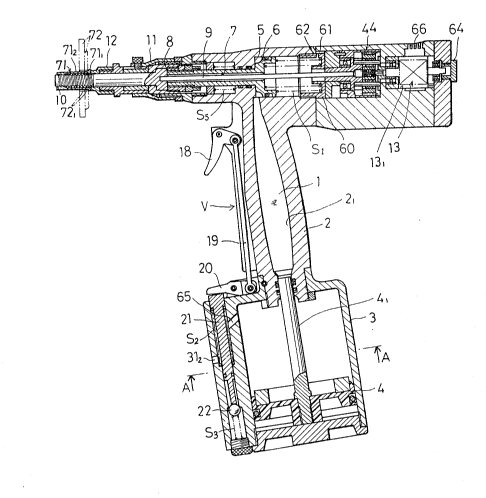
Figs. 1 to 3 generally show a hydropneumatic gun
for setting blind-rivet nuts in accordance with the
present invention, which comprises:
a body frame 2 including an oil housing 2~ for
housing oil l;
an air cylinder 3 disposed under the frame 2;
an air piston 4 for pressurizing the oil 1 in the
air cylinder 3,
an oil cylinder 5 communicating with the oil
housing 21 at the upper portion of the frame 2;
an oil piston 6 disposed in the oil cylinder 5;
a returning spring Sl for advancing the oil piston
6;
a pivot member 8 of a screw mandrel, to be discuss-
- 9 -
ed later, secured to the front end of the oil piston 6;
a turning force transmission square shaft 9 having
a square section lnsertingly fitted in a through-hole 7
in the axis of the oil piston 6 such that the shaft 9 is
5 rotatable in th~- circumferential direction;
the screw mandrel 10 engaged with the front end of
the square shaft 9 such that the screw mandrel 10 is
rotatable integrally with the square shaft 9 in the
circumferential direction;
a connector 11 mounted on the body frame 2 at the
front end thereof; and
a nose piece 12 mounted on the connector 11 at the
front end thereof.
An air motor 13 for rotatingly driving the square
lS shaft 9 is disposed at the rear portion of the square
shaft 9. The air cylinder unit 3 includes an air control
mechanisr.t AC having an compressed air supply port 14. An
air motor driving air guide passaye 17 is formed between
the air motor 13 and the compressed air supply port 14
20 through an air passage lS having a valve seat and an air
branch passage 16.
The air guide passage 17 has a communication hole
171 communicating with the supply port 14 (Fig. 3), a
passage 172 and an air hose 173. An openable valve mech-
25 anism V is disposed between the air guide passage 17 and
~3D~
--10--
the air motor 13.This mechanism V has:
a trigger 18 at the front side of the frame 2;
a connecting rod 19 pivotally connected to the
5 trigger 18;
a lever 20 having a base end pivoted to the con-
necting rod 19 and an intermediate portion pivoted to
the air cylinder 3 at the upper portion thereof;
a pusher 21 slidably inserted into an insertion
10 hole in the air control mechanism AC while the upper end
of the pusher 21 is pressure-contacted to the underside
of the tip of the lever 20 by a spring S2; and
a valve body 22 pressure-contacted to the valve
seat in the air passage 15 by a spring S3.
The valve mechanism Y normally closes a passage
between the compressed air supply port 14 and the air
guide passage 17 by the valve body 22 biased by the
spring S3. When the trigger 18 is pulled toward the
operator, the pusher 21 is lowered through the connect-
20 ing rod 19 and the lever 20 against the spring load of
the spring S2. The lower end of the pusher 21 pushes
down the valve body 22 against the spring load of the
spring S3, causing the compressed air supply port 14 to
communicat~ with the air guide passage 17.
An air piston moving air guide passage 24 is formed
be~ween the air supply port 14 and an air guide hole 23
(Fig. 4) in the air cylinder 3 at the air piston 4
moving side. The air guide passage 24 communicates with
the supply port 14 through the passage 15 and the other
5 air branch passage 25. A spool 27 for opening and
closing the air guide passage 24 is slidably fitted in a
communication hole 26 which communicates with the air
guide passage 24. A spool controlling air guide chamber
28 is formed between the communi~ation hole 26 and the
10 supply port 1~ through an air flowing hole 29. This air
guide chamber 28 is adapted to move the spool 27 by air
in such direction as to close the air guide passage 24.
Air is guided from the air supply port 14 into the air
guide chamber 28 through the air flowing hole 29 in the
15 spool 27. The air thus guided into the air guide cha~ber
28 pushes the spool 27 downward to close the passage 24.
By the pressure of air supplied from the other air
branch passage 25, the spool 27 .is pushed in such direc-
tion as to close the passage 24. More specifically, the
20 pushing force corresponds to the areas of the top sur-
face 271 and the underside surface 27~ of the large-di-
ameter portion of the spool 27. Accordingly, when air is
guided into the air guide chamber 28, the pushing force
applied to the top surface 271 is greater than that
25 applied to the underside 272. Therefore, the spool 27
~L3~
-12-
receives a pushing force in such direction as to close
the passage 24.
Fig. 3 shows an air discharge passage 30 for dis-
charging air in the spool controlling air guide chamber
5 280 This air discharge passage 30 is disposed between
the air guide chamber 28 and an air discharge port in
the gun body in the vicinity of a power transmission
mechanism to be discussed later. The air discharge pas-
sage 30 includes passges 301 and 32 which communicate
10 with the air guide chamber 28, and an air hose 303. Fig.
3 also shows a discharge passage 311 and a discharge
hole 312 for discharging the air in the air cylinder 3
to the outside of the gun body.
Disposed in the air motor driving air guide passage
15 17 is an air passage changeover spool of a rotation
direction changeover mechanism 32 for switching the
rotation direction of the air motor 13, to be discussed
later.
As shown in Fig. 5, the mechanism 32 has a push
20 member P and an air passage changeover spool 37 disposed
in the air guide passage 17. The push member P includes:
an adapter nut 33 threadedly connected to the oil piston
6 at the tip thereof; a guide plate 34 fittingly insert-
ed into the oil piston 6 at the rear side of the adapter
25 nut 33 such that the guide plate 34 is movable back and
~1313~
forth; an adjusting screw 35 threadedly connected to the
guide plate 34 at the projection thereo~; a push rod 36
transversely movably inserted in the gun body such that
the tip of the push rod 36 can come in contact with the
5 tip of the adjusting screw 35; and a divided push rod
36' transversely movably inserted in the gun body while
the rod 36' is in contact with the rear end of the push
rod 36.
The spool 37 is disposed such that the tip thereof
10 comes in contact with the rear end of the divided push
rod 36'. The push member P is normally biased to the
position shown in Fig. 5 by a returning spring S4.
Thus, the air passage changeover spool 37 is
fittingly inserted in a bushing 38 communicating with
15 the air guide passage 17 as shown in Fig. 6 (a) and (b),
and is normally biased by the returning spring S4 in
such direction as to rotate the air motor 13 forward.
The following describes how to switch the air passage by
this spool 37.
As shown in Fig. 5 and Fig. 6 (a), the changeover
spool 37 is normally moved forward by the spring load of
the spring S4. Air supplied through the passage 17 flows
in an air guide hole 39 in the bushing 38 and an air
delivery hole 40 which communicates with a forward rota-
25 tion side air jet port (not shown) in a housing space
-14-
131 for housing the air motor 13. The air is then jetted
into the housing space 131. Thus, the air is a driving
force for rotating the air motor 13 forward. When the
oil piston 6 is retracted by the oil pressure, the
5 adapter nut 33 of the push member P is also retracted to
retract the guide plate 34 against the spring load of a
spring S5. Accordingly, the adjusting screw 35, the push
rod 36 and the divided push rod 36' are also retracted,
and the changeover 5pool 37 is pushed rearward by the
10 rear end of the divided push rod 36'.
At this time, when the front end of the changeover
spool 37 is retracted up to an air guide hole 41 in the
bushing 38 at the front thereof as shown in Fig. 6 (b),
air is guided from this hole 41 into the bushing 38 to
lS securely move the changeover spool 37 rearward. While
the changeover spool 37 is moved rearward, the spool 37
causes the air delivery hole 40 to communicate with an
exhaust hole 43 and also causes the air guide hole 39 to
communicate with an air delivery hole 42 which communi-
` 20 cates with a reverse rotation side air jet hole tnot
shown) in the air motor housing spacs 131. Thus, the air
is a driving force for rotating the air motor 13
reversely.
Disposed between the air motor 13 and the screw25 mandrel 10 is a power transmission mechanism 44 for
-15-
transmitting a forward/reverse rotation clriving force of
the air motor 13 to the screw mandrel 10.
As shown in Figs. 7 and 8, this mechanism 44 in-
cludes:
a plurality of planetary gears 46 which mesh with a
transmission gear 45 disposed at the end of the rotary
shaft of the air motor 13;
pivotal support members 48 and 49 of the gears 46
for pivotally supporting the gears 46 through pins 47 at
10 both ~ront and back positions of the gears 46;
a clutch 50 itted to the gears 46 at their periph-
eries;
a returning spring S6 for rotating the clutch 50 in
a predetermined circumferential direction; and
lS a clutch regulating plate 56 having
a housing chamber 51 of the spring S6,
a slot 53 into which a knock pin 52 standing
from the clutch 50 is fitted, and
a through-hole 55 which communicates with a
communication hole 54 in the clutch 50 as
necessary.
The clutch regulating plate 56 covers the clutch 50
in the arrangement shown in Figs. 7 and 8.
Both pivotal support members 48 and 49 are rotat-
25 able simultaneously with the rotation of the gears 46.
-16-
The clutch 50 is resiliently hooked on the regulating
plate 56 through the spring S6. Accordingly, while kurn-
ing on their axes, the planetary gears 46 are normally
yuided by and rotated around an internal gear 57 in the
5 inner periphery of the clutch 50. The front pivotal
support member 48 is provided in the axis thereof with a
square hole 58 with which the rear end of the square
shaft 9 is engaged. Accordingly, the forward/reverse
rotation force of the air motor 13 is transmitted to the
10 front screw mandrel 10 through the transmission gear 45,
the planetary gears 46, the pins 47, the pivotal support
member 48 and the square shaft 9.
The air hose 303 of the air discharge passage 30
communicates with the through-hole 55 in the regulating
15 plate 56 through an air discharge hole 59. The through-
hole 55 is adapted to communicate with the co~unication
hole 54 in the clutch 50 when the clutch 50 is switched.
Accordingly, when the clutch 50 is switched, the air
hose 303 communicates with an alr discharge port 62 in
20 the gun body through a passage 61 formed between a frame
cap 60 in the gun body and the inner wall thereof.
The following will discuss a series of operations
of the hydropneumatic gun for setting blind-rivet nuts
in accordance with the embodiment above-mentioned.
The trigger 18 i5 pulled to open the valve body 22,
ilL3{~S6~
-17-
causing the compressed air supply port 14 to communicate
with the air guide passage 17. Air is then supplied to
the air motor 13 to rotate the air motor 13 forward.
Then, the screw mandrel 10 is also rotated forward. In
5 such state, a nut 71 is threadedly mounted on the screw
mandrel 10. The nut 71 is fittingly inserted into mount-
ing holes 721 in two panels 72, and a flange 711 of the
nut 71 is pressed to the lateral sides of the mounting
holes 721 to stop the rotation of the nut 71. Then, the
10 screw mandrel 10 (the gun body side) is relatively
advanced. Such advancement causes the flange 711 of the
nut 71 to be securely connected to the nose piece 12.
Then, the screw mandrel 10 is locked to stop its rota-
tion. However, since the forward rotation of the air
15 motor 13 is continued~ the transmission gear 45 turns
the planetary gears 46 on their axes. Accordingly, the
clutch 50 is rotated forward up to a predetermined angle
position against the spring load of the spring S6. This
predetermined angle position refers to the position
20 where the knock pin 52 in Fig. 8 regulates the rotation
of the clutch SQ. When the clutch 50 is rotated up to
this position, the communication hole 54 in the clutch
50 communicates with the through-hole 55, causing the
air hose 303 in the air discharge passage 30 to communi-
25 cate with the discharge port 62.
~a3~i6~
~18-
By such communication of the air hose 303 with the
discharge port 62, air guided into the air guide chamber
28 is discharged to the outside of the gun body through
the air discharge passage 30. Accordingly, the air pres-
5 sure in the air guide chamber 28 is decreased to release
the control of the spool 27. Therefore, the pressure of
air supplied through the supply port 14 and the branch
passage 25 is received by the underside 272 of the
large-diameter portion of the spool 27. The spool 27 is
lO then pushed upward, causing the air branch passage 25 to
communicate with an air guide passage 24'. Accordingly,
the air is supplied into the air cylinder 3 through the
passage 24' and the cylinder air guide hole 23 to move
the air piston 4. The piston rod 41 enters the oil
15 housing 21 to pressurize the oil l therein. Such pres-
surization to the oil 1 causes the oil piston 6 to be
retracted against the spring load of the returning
spring S1. However, the pivot member 8 at the front of
the oil piston 6 retracts the screw mandrel lO simul-
20 taneously with the retraction oF the oil piston 6.
Therefore, the sleeve 712 of the nut 71 is outwardly
expanded and deformed to secure the panels 72 between
the flange 71l and the deformed sleeve. Thus~ deforma-
tion of the nut 71 can be achieved. Such deformation of
25 the nut 71 is made while the oil piston 6 is moved to a
i;6`~
--19--
predetermined rear portion by the oil pressure.
As discussed earlier, when the oil piston 6 is
retracted to deform the nut 71, the air passage change-
over spool 37 is retracted by the push member P to
5 rotate the air motor 13 reversely. When the air motor 13
is reversely rotated, the clutch 50 is returned to the
original position by the spring load of the returning
spring S6 and the reverse rotation of the planetary
gears 46 to close again the air discharge passage 30.
10 Accordingly, air is guided again into the air guide
chamber 28 to push the spool 27 downward. This cuts off
the communication of the air branch passage 25 with the
passage 24'. This eliminates the working force of moving
the air piston 4 to stop the pressurization to the oil l
15 by the piston rod 41. Therefore, the oil piston 6 is
returned forward by the spring load of the returning
spring Sl. However, while the valve body 22 is pushed
down to supply air to the air guide hole 41 in the front
o~ the bushing 38 of the air motor rotation direction
20 changeover mechanism 32, the spool 37 is held at its
current position by the air pressure to continue the
reverse rotation of the air motor 13. Accordingly, while
being reversely rotated, the screw mandrel lO is
retracted and separated from the nut 71 which is secured
25 to the mounting holes 721 in the panels 72. Thereafter,
-20-
when the finger is released from the trigger 18 to push
up the valve body 22, the changeover spool 37 is return-
ed to the original forward position by the spring load
of the returning spxing S4. Consequently, the push mem-
5 ber P is also returned to the original position, thusproviding the normal state.
Fig. 5 also shows a grip 63 attached to the rear
portion of the push rod 36 of the push member P. If the.
threaded connection of the nut 71 to the screw mandrel
10 10 was not properly made, the grip 63 can be pulled to
manually retract the push member P. The air motor 13 can
be emergently rotated reversely to remove the nut 71~
There is also disposed a screw lid 64 removably
attached to the rear end of the air motor housing 131.
15 If the air motor 13, the square shaft 9, the screw
mandrel 10 or the like cannot be rotated or are defec-
tively rotated due to unexpected causes, the screw lid
64 can be removed and the rotary shaft of the air motor
13 can be manually rotated with a screwdriver or the
20 like to provide normal conditions. Fig. 1 also shows an
air discharge passage 65 in the air cylinder 3, and a
discharge pipe 66 for discharging surplus air supplied
into the casing of the air motor 13.
In the embodiment above-mentioned~ the air motor
25 rotation direction changeover mechanism 32 includes the
-21-
air passage changeover spool 37 in the gun body, the
returning spring S4 disposed at the rear side of the
spool 37 and the spool push member P coacting with the
oil piston 6. The mechanism normally advances the spool
5 37 by the returning spring S4, causing the air passage
in the spool 37 to communicate with the passage of the
air motor 13 at its forward rotation side. When the oil
piston 6 is retracted, the push member P retracts the
spool 37, causing the air passage in the spool 37 to
10 communicate with the passage of the air motor 13 at its
reverse rotation side. Such arrangement can reduce the
space required for housing the spool 37, thus enabling
the hydropneumatic gun for setting blind-rivet nuts to
be made in compact design in its entirety.
If the threaded connection of the nut 71 to the
screw mandrel 10 was not properly made, the spool push
member P can be manually retracted to rotate the air
motor 13 reversely to remove the nut 71.
Figs. 11 to 15 shows a second embodiment of the
20 present invention, in which like members are designated
by like numerals added by 100 which are used in Figs. 1
to 10.
In the second embodiment, a square shaft 109 is
engaged with a screw mandrel ilO through a square shaft
25 piece 1091 secured to the front end of the square shaft
-22-
:LO9 .
Disposed between an air motor 113 and a compressed
air supply port 114 is an air motor dr.iving air guide
passage 117 through an air branch passage 115.
SDisposed in the air guide passage 117 is a valve
mechanism V for opening and closing the passage 117~ of
which valve body 122 is normally biased by the spring
load of a spring S2 in such direction as to close the
passage 117. When the valve body 122 is pushed aga.inst
10 the spring load of the spring S2 in the direction shown
by an arrow in Fig. 11, the passaye 117 is opened,
causing the air supply port 114 to communicate with the
air motox 113 through the passage 117 to rotate the air
motor 113.
15Also disposed in the air guide passage 117 is a
rotation direction changeover mechanism 132 for switch-
ing the rotation direction of the air motor 113 by a
predetermined pressing force to oil 101.
The mechanism 132 includes a bushing 138 communi-
20 cating with the air guide passage 117, an air passagechangeover spool 137 fittingly inserted in the bushing
138, a returning spring S4 for biasing the spool 137 to
the forward rotation side of the air motor 113 and a
spool 1371 for pushing the spool 137 to the reverse
; 25 rotation side of the air motor 113 by a predetermined
~'~
-23~
pressing force to the oil 101. The following will
discuss how the air passage is switched by the mechanism
132.
As shown in Figs. 11 and 14, the changeover spool
5 137 is normally moved forward by the spring load of the
spring S4 and the pushing spool 1371 is normally moved
forward by the spring load of the returning springs S4
and S7. Air supplied through the passage 117 passes
through an air guide hole 139 in the bushing 138 and an
10 air delivery hole 140 which communicates with a ~orward
rotation side air jet port (not shown) in an air motor
housing space ll31. The alr is then jetted in the
housing space 1131. Thus, the air lS a driving force for
rotating the air motor 113 forward. As discussed later,
15 when a pressing force to the oil 101 exceeds a prede-
termined value, the pushing spool 1371 is moved rearward
against the spring load of the returning springs S7 and
S4. The changeover spool 137 is therefore pushed rear-
ward as shown in Fig. 15. At this time, however, when
20 the front end of the changeover spool 137 is retracted
up to an air guide hole 141 in the front of the bushing
138, air is guided from the guide hole 141 into the
bushing 138 to securely move the changeover spool 137
rearward. While the changeover spool 137 is moved rear-
25 ward, the spool 137 causes the air delivery hole 140 to
3L3~56~L
-24-
communicate with an exhaust hole 143 and also causes the
air guide hole 139 to communicate with an air delivery
hole 142 which communicates with a reverse rotation side
air jet hole (not shown~ in the air motor housing space
5 1131. Accordingly, the air thus supplied is a driving
force for rotating the air motor 113 reversely.
In a power transmission machanism 144l a clutch 150
is resiliently hooked on the gun body through a spring
S6 .
There are formed a spool 127 controlling air guide
chamber 128, ~nd an air discharge port 1591 in the
vicinity of the power transmission mechanism 144. Dis-
posed between the air guide chamber 128 and the air
discharge port 1591 is an air discharge passage 130 for
15 discharging air in the air guide chamber 128. Through
the passage 130, the air guide chamber 128 communicates
with an air delivery hole 159 in the front of the clutch
150 of the power transmission mechanism 144. The air
delivery hole 159 is adapted to communicate with an air
20 discharge port 1591 through a communication hole 154 in
the clutch 150 when the clutch 150 is rotated to a pre-
determined angular position by a predetermined turning
torque to be discussed later.
By the communication of the air delivery hole 159
25 with the discharge port 1591, air guided in the air
-25-
guide chamber 128 is discharged outside of the gun body
through the air dischare passage 130. This decreases the
pressure of air in the air guide chamber 128 to release
the control on the spool 127 t causing the spool 127 to
5 be pushed in such direction as to open a passage 124.
When the passage 124 i5 opened, aix is supplied into an
air cylinder 103 to move the air piston 104. A piston
rod 1041 is pushed into an oil housing 1021 to
pressurize the oil 101 therein. This retracts an oil
10 piston 106 and the screw mandrel 110 at the same time,
enabling a sleeve 1712 of a nut 171 to be outwardly
expanded and deformed.
Through an oil passage 1022, an oil cylinder 105
communicates with a guide cha~ber 173 for guiding a
15 working oil for the pushing spool 1371 in the air motor
rotation direction changeover mechanism 132. According-
ly, a predetermined oil pressure as above-mentioned is
applied to this oil guide chamber 173. Upon completion
of deformation of the nut 171, such oil pressure causes
20 the pushing spool 1371 to be moved rearward, and the air
motor 113 is reversely rotated as mentioned earlier.
A bolt 175 is disposed for adjusting the spring-
load of the returning spring S4.