Note: Descriptions are shown in the official language in which they were submitted.
~3U~9Zl
TITLE: DETERMINATION OF THE REGISTER ERROR
IN MULTI-COLOU~ PRI~TING
The invention relates to a register-error-
determining device of the kind stated in the
defining clause of Claim 1 and also to register
marks intended for use with said device.
In multi-colour printing, there must be highly
precise correspondence between the part-images
printed with the individual printing inks. To
check the relative positional differences of the
individual part-images - the so-called register
error - use is made usually of co-printed register
marks which are evaluated visually or, nowadays,
even photoelectrically and possibly also with the
aid of a computer. Examples of such more or less
automated photoelectric register-measuring systems
are described in West German Patent 32 48 795,
United States Patent 4,534,28~ and West German
Patent 32 26 078 These systems all operate on-
line on the running printing press with special
register marks and appropriately adapted,
conventional scanning apparatuses. Hand-held
devices of a comparable nature for off-line
operation have so far been unknown. In addition,
on-line and off-line systems have also become known
which scan the register marks with television
cameras and display them. However, such systems
are relatively complex and too elaborate for many
applications.
The intention of the present invention is to create
a hand-held device, specially tailored for off-line
operation, for detecting the register error, the
130~9~1 ~
keynotes of the device being its simplicity of design
as well as its ease and reliability of use, while
ensuring, however, that the pertinent requirements in
terms of precision are met and that no excessive
requirements are placed on the positioning accuracy of
the measuring device.
The device according to the invention proceeds from the
device of the kind defined in the defining clause of
Claim 1 and is characterized according to the invention
by the features contained in the characterizing part of
Claim 1. Particular embodiments emerge from the
dependent claims.
.,
In the following, the invention is described in greater
detail with reference to the drawings, in whlch:
Fig. 1 shows a schematic representation of a
specimen embodiment of the invention
with circular scanning-head motion;
Fig. 2a and 2b each show a register mark for five-
colour printing, in one case with and
in one case without register error;
' .
Fig. 3 shows a sketch to explain the
calculation of the register error in
the case of circular scanning;
Fig. 4 shows a variant of a register mark for
circular scanning;
Fig. 5 shows a basic sketch of a two-
dimensionally operating scanning
apparatus;
.
.~ ; .," ,.,
~3t~0~Zl
.,
Fig. 6 shows a register mark suitable for
linear scanning; and
Fig. 7 shows a further variant.
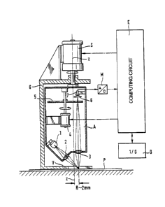
The device shown in Fig. 1 is in the form of a hand-
held device, all parts being accommodated in a housing
G, which is shown here only in outline. The
construction of the device are very
largely similar to those of hand-held densitometers~
- ,
Of course, other designs are also
possible.
Accommodated in the housing G are a rotatable scanning
head A, a stepping motor S ~or driving the scanning
head, a measuring transducer M, a control and computing
circuit E and an input/output unit D, whereas
thesé control keys can comprise a dlsplay and/or
interfaces to further devlces~ The scanning head A is
rotatable about a vertical axis Z and contains a light
source 1, illumination optics 2 and measuring optics 3,
a filter wheel S driven by means of a motor 4, an
aperture diaphragm 6 and a photoelectric recéiver 7
which is connected to the measuring transducer M.
Except for the fact that the scanning head A is
rotatable and the scanning data are evaluated
differently, the device is thus, as already mentioned,
approximately identical to a commercially available
hand-held densitometer, with the result that further
explanatory remarks on the construction are superfluous.
In operation, the device is placed by hand on the
printed sheet P which is to be evaluated, such that a
.
13~)~'92~
.
,
co-printed register mark comes to lie inside a sighting
aperture V provided in the housing G, and then the
scanning operation is triggered automatically or by
means of pressing a button. In this connection, the
lamp 1 produces on the printed sheet P a very fine,
punctiform light spot LF (Fig. 3) which is imaged onto
the aperture diaphragm 6 via the measuring optics 3.
The photosensitive cell 7 measures the light penetrating
through the aperture diaphragm 6. The light spot is
approximately 2 mm outside the rotation axis Z of the
scanning head A and moves, therefore, during the
rotation of the scanning head, along a circular path K
- the printed sheet is scanned circularly. The filter
wheel 5 serves for the colour splitting of the
measuring light and makes it possible to allocate the
scanning values to the indlvidual printing colours.
. .
Flg. 2a and 2b show an embodiment of a register mark PM
suitable for circular scanning with the previously
descrlbed device, in this case, for example, for five-
colour printing (four colours plus black). The mark PM
comprises four angles 11 - 14 and one cross 15. The
angles each consist of two sides 11a, 11b - 14a, 14b
which are inclined at 90 degrees to one another; in the
manner shown, the angles are disposed at regular
intervals in a circle about the centre of the cross.
Each angle is of a different colour and originates
accordingly from a different printing operation.
Although the individual parts of the register mark have
defined nominal positions in relation to one another
~Fig. 2a), they do not cover one another even in the
case of an ideal print, i.e. one without register
error. Therefore, this register mark is not suitable
for visual inspection. In order, in addition to the
mechanized determination of the register error, also to
;. .`''
:' ,
:
~3~ 9Zi
permit visual examination, the register mark may
contain in its centre a further four cruciform elements
16 - 19 which under ideal conditlons cover one another.
Fig. 2a shows the ideal case, Fig. 2b showing a
regi3ter mark indicating a register error.
The register mark shown here by way of example can, of
course, be varied in diverse ways. In particular, by
appropriate adaptation of the division of the circle
and of the angles, it is possible for it to be extended
or reduced to cover more or fewer printing colours.
Also, for example, the cross 15 in the centre of the
mark can be replaced by four lines arranged in the
shape of a cross or by a similar pattern.
Furthermore, of course, it is also possible for the
parts provided for visual inspection to oe dispensed
with.
Fig. 3 explains the determination of the ~egister
error. This is understood to mean the misalignment in
the printing directlon (direction of movement of the
printed sheet in the printing press) and in the
transverse direction of each individual part-
image in relation to a freely selectable reference
image ~usually black).
The rotating scanning head A scans the register mark
PM along a circular path K. The diameter of this
circular path is, for example, approximately 4 mm. The
centre of the clrcle glven by the projection of the
rotation axis Z of the scanning head A is identified
by Z. The light spot LF moves in angular increments of
e~g. < 0.36 degrees ~^-1000 increments per revolution) in
a circle. Of course, a higher resolution i5 also
posslble, for example approximately 2000 or 3000
i
!~ - s
.~,................... .
...,.. .
. ~ _
~ 13()C~921
increments per full revolution. Since the radius of
the scanning path is fixed, the position of the light
spot hF is unambiguously defined by its angular
position. The zero position (angle reference line),
which can be permanently set at any desired position,
is identified by ~ O in Fig. 3. The printing
direction and the transverse direction are indicated by
the coordinate axes x and y.
For reasons of clarity, Fig. 3 shows only a part of the
register mark PM shown in full in Fig. 2a and 2b. In
this case, in Fig. 3, only the black centre cross 15
and a coloured angle 12 are shown. When, on its
scanning path, the light spot sweeps over one of the
line-shaped sides of thç parts of the mark, there is a
noticeable change in reflection, which is evaluated in
the control and computing circuit E in accordance with
the customary methods in order to determine the points
of intersectlon. The thus determined angular positions
of these points of intersection are identified by ~ 1
to oC~ . From these angles, it is now possible to
-~calculate the distances ~ x and ~ y between the
--- centre cross 15 (used here as a reference by way of
1~ example) and the angle 12; this is done using the
".~
~- equations
a ~
2a ~ln ~ -- J ~ln ~ J
~ I
5' - Z ~2 - at ~
~y ~ 2~ n ~ z . ~ 31n ~ 2
In a similar manner it is possible to calculate the
distances with respect to the other parts of the mark.
~t
~ ~i 6
'~'
,"~, .
!-
13C)C~9~:i
By a trivial calculation it can be shown that thedetermination of ~ x and ~ y is independent of the
positioning of the device on the printed sheet, both
with respect to the distance from the theoretical
centre polnt of the mark and also with respect to the
angular position of the device in relation to the
coordinate network x-y. Of course, the device must be
roughly positioned at least such that the register mark
is not outside the (here) circular scanning region of
the device.
The reflection signals supplied by the photoelectric
transducer 7 are conditioned in the amplifier - A/D
convertor M. The calculation of distances ~ x and ~ y
and, from them, of the register error (by subtraction
of the defined nominal distancés) is performed in an
evaluation apparatus contained in the control and
computing circuit E or formed by the latter. The
control and computing circuit E also provldes the
control of the drive motor3 S and 4 as wR11 as of the
light source 1 and checks and coordinates all sequences
necessary for the measuring operation, as is the case
also ln a modern computer-controlled hand-held
densitometer. The operation of the dsvice and the
indication of the measurement results are accomplished
by way of the input/output unit D, once again in a
similar manner to hand-held densitometers.
The line widths of the register mark shown in Fig. 2a
and 2b are preferably approximately 0.1 mm, the mark
itself having an extent of, for example, approximately
7 x 7 mm~ . The distances between two neighbouring
parallel sides of parts of the mark belonging to
different colours are approximately 0.8 mm. This
provides a practical arrangement with high precision ~0.01 mm).
,~
~_ I
13~)09; 1 11
The scanning of the coloured parts of the mark may be
single- or multi-channel, sequential or parallel. In
the case shown, colour splitting is accomplished by
colour filters disposed in a filter wheel. Of course,
it is also possible to use other methods. It is merely
important that the lines of the individual parts of the
mark can be precisely located and can be allocated to
the corresponding printing colours.
To increase the measuring reliability, the register
mark may be configured as in Fig. 4. In this case,
there are three each of the (in this case four) coloured
angles 11 - 14, as a result of which the measurement is
provided with redundancy and any errors and
uncertainties can be eliminated. Once again,
the arrangement of the indi~idual coloured angles is
such that, even with the greatest ant~cipated register
error, there ls no printing of parallel sides one on
top of the other.
.
To further improve the measuring accuracy and
reliability, the scanning of the register marks may
also be two-dimensional. This is understood to mean
that the scanning spot does not move along one
individual linear path, but sweeps over a more or less
large area and scans the latter point by point. As
shown in Fig. 5, for example, this may be accomplished
by means of a line of diodes (photodiode array) 30
consisting of a multiplicity of individual light-
sensitive diodes. This line of diodes rotates about an
axis z and, in doing so, scans the register mark PM
along a number of concentric circular tracks k
corresponding to the number of photodiodes.
,~ ~'
~_ I
-
13()C~9~Pl
An alternative to this consists, for example, in that
only one individual photosensitive cell be allowed to
rotate and, instead, the radius of the scanning track
be changed.
A further alternative provides for the use of a
stationary two-dimensional photodiode array or
similar covering the entire scanning region, with the
point-by-point scanning being accomplished by selective
interrogation of the individual photodiodes.
Given appropriate construction of the register mark,
the measurement can be performed without mechanical
scanning of the register mark by using two lines of
photodiodes (line array) disposed, for example, at
right angles to one another.
Even lf using a line or area array wlth
linear,mechanical scanning of the register mark in only
one direction, a comprehensive detection of the entire
~register mark is possible.
- ~ If, in particular, colour-capable arrays or the
combination of optic filters and arrays are used, then,
in conjunction with suitable software means, it is
-~possible to have the colour-oriented measuring of the
register marks without it being necessary to comply
~w1th a fixed colour sequence of the register marks.
,
The register marks need not necessarily be scanned
along a clrcular track. For example, given appropriate
design of the register marks and adaptation of the
scanning apparatus, it may also be advantageous to have
linear scanning~ Fig~ 6 shows an example of this. In
this case, the register mark PM consists of
~1~ 9
13~ Zl
conventional cross-type register marks 41 - 45.
Through aperture diaphragms suitably disposed in the
optical path, the scanning apparatus A produces two
scanning lines S1 and 52 disposed at right angles to
one another, with the entire device being so positioned
above the register mark in operation that the two
scanning lines are each parallel to one side of the
cross-type register marks. By means of a stepping
motor or other suitable drive, the scanning head and
with it the scanning lines 51 and 52 are scanned in a
diagonal direction d. In this connection, each
scanning line detects only the bars of the cross-type
register marks parallel to it. From the succession of
the individual bars it is then possible in simple
manner to determine their relative positions and thus
the register error.
Scanning with the two scanning lines 51 and 52 is
performed separately for both lines. For this purpose,
either two different scanning systems may be provided,
or means are provided to produce one single scanning
line which can be brought into two positions turned
through 90 degrees with respect to one another. In
this case, scanning would be performed, for example, in
two operations one after the other.
Fig. 7 shows an embodiment of a register mark which is
particularly suitable for linear scanning. It consists
of a series of first parallel lines 61 - 64 and a
series of second parallel lines 65 - 69 inclined at 45
degrees with respect to the first lines. Each line in
a series is printed in another of the printing colours
involved. The nominal distances between the individual
parallel lines are fixed such that, even with the
maximum anticipated register error, the lines are not
,
I 13(~(;P9~1
printed one on top of the other. In the drawing, some
of the positional fluctuation ranges of the individual
register lines are indicated by fields 71 - 76 outlined
by dashed lines.
It is practlcal for this register mark to be scanned
along the line d via two scanning gaps 81 and 82
incllned at 45 deqrees with respect to one another,
similarly to the version shown in Fig. 6. Once again,
in this connection, two separate scanning systems for
each gap direction may be provided, or one scanning gap
which is variable in its direction. The size
relationships between register mark and scanning gaps
emerge from Fig. 7 which is to scale. The line~'width
is approximately 0.1 mm, the size of the entire register
mark being approximatély 4.5 x'13 mm.
The register mark in Flg; 7 corresponds, in its basic
pxinciple, to thatone descr~ m the lnitially mentioned
' DE-C-3226078, yet, compared with the latter, has the
advantage that it permits a considerably more
precise and more reliablé measurement (lines instead of
edges - widening of point has no lnfluence on measured
result) and, in add'~tion, it is considerably smaller
and more compact, based on the same number of printing
- colours.
- The scanning head is aligned with'the aid of the sight
(V). In addition, means integrated into the device are
conceivable for providing visual assistance when
aligning the scanning head on the register mark. Such
means are, for example, magnifying lenses, ground-glass
discs or optically/electronicallY controlled small
screens.
~ , ,
.
` 130092i ~
Connection to the optical path is achieved preferably
by a beam splitter or a semipermeable mirror.
12
. 1~
~