Language selection

Search

Patent 1301081 Summary

Third-party information liability

Some of the information on this Web page has been provided by external sources. The Government of Canada is not responsible for the accuracy, reliability or currency of the information supplied by external sources. Users wishing to rely upon this information should consult directly with the source of the information. Content provided by external sources is not subject to official languages, privacy and accessibility requirements.

Claims and Abstract availability

Any discrepancies in the text and image of the Claims and Abstract are due to differing posting times. Text of the Claims and Abstract are posted:

  • At the time the application is open to public inspection;
  • At the time of issue of the patent (grant).
(12) Patent: (11) CA 1301081
(21) Application Number: 1301081
(54) English Title: RETAINER ASSEMBLY
(54) French Title: DISPOSITIF D'ARRET
Status: Expired and beyond the Period of Reversal
Bibliographic Data
(51) International Patent Classification (IPC):
  • F16D 65/08 (2006.01)
  • F16B 5/06 (2006.01)
  • F16B 21/07 (2006.01)
  • F16D 65/09 (2006.01)
(72) Inventors :
  • TEMPLE, ROBERT BRUCE (United States of America)
  • JOHANNESEN, DONALD DIXON (United States of America)
(73) Owners :
  • ALLIED-SIGNAL INC.
(71) Applicants :
  • ALLIED-SIGNAL INC. (United States of America)
(74) Agent: MACRAE & CO.
(74) Associate agent:
(45) Issued: 1992-05-19
(22) Filed Date: 1988-04-22
Availability of licence: N/A
Dedicated to the Public: N/A
(25) Language of filing: English

Patent Cooperation Treaty (PCT): No

(30) Application Priority Data:
Application No. Country/Territory Date
099,869 (United States of America) 1987-09-22

Abstracts

English Abstract


RETAINER ASSEMBLY
ABSTRACT OF THE DISCLOSURE
The retainer assembly (10) comprises a longi-
tudinally extending retainer body (12) having an enlarged
diameter or head member (14) at one end and an arrow-
shaped or flared member (16) at the other end. A V-shaped
leaf spring (20) has an opening (24) at the bottom of the
V-shaped opening (22) which receives the retainer body
(12) so that the spring (20) is disposed between the head
member (14) and a surface (31) of a first member (30). The
retainer body (12) extends through an opening (32) in the
first member (30) and the flared member (16) is resili-
ently captured within a resilient receiving member (50)
disposed within an opening (46) of the second member (40).
The opening (46) in the second member (40) is in a second
surface (44) disposed apart from a first surface (42) of
the second member (40) which engages the first member
(30). The receiving member (50) flexibly traps the flared
member (16) after insertion therethrough so that the leaf
spring (20) biases the first member (30) into engagement
with the second member (40).


Claims

Note: Claims are shown in the official language in which they were submitted.

THE EMBODIMENTS OF THE INVENTION IN WHICH AN EXCLUSIVE
PROPERTY OR PRIVILEGE IS CLAIMED ARE DEFINED AS FOLLOWS:
1. A retainer assembly for maintaining a first
member in engagement with a second member, comprising a
retainer body which extends longitudinally between a head
member at one end and a flared member at the other end, a
resilient member having an opening receiving the retainer
body and abutting the head member, the resilient member
disposed between said head member and a surface of the first
member so that the retainer body extends through an opening
in the first member, the second member having a pair of
surfaces spaced apart from one another and one of the pair
of surfaces having an opening, a receiving member disposed
within the opening in the second member and having a passage
therethrough, the receiving member gripping flexibly the
second member so that insertion of the flared member through
the passage in the receiving member causes the receiving
member to be deformed resiliently by the flared member and
then return toward an initial position wherein the receiving
member retains the retainer body by means of engagement with
the flared member, the resilient member biasing the head
member so that the flared member retracts slightly axially
the receiving member through the opening in the second member
to cause the receiving member to capture securely the flared
member, the receiving member including a stepped exterior
circumference which engages said opening in the second member
so that the slight axial retraction of the receiving member
through the opening in the second member causes the receiving
- 4 - 13177/rn

member to contract and engage more tightly the flared member,
and the retainer assembly biasing the first member into
engagement with the second member.
2. The retainer assembly in accordance with claim
1, wherein the receiving member includes at least one finger
portion extending radially inwardly into the passage to
provide a shoulder for engagement with said flared member.
3. The retainer assembly in accordance with claim
2, wherein the flared member comprises a substantially arrow-
shaped head.
4. The retainer assembly in accordance with claim
3, wherein the receiving member comprises a member divided
into quadrants, the quadrants connected via living hinge
connections.
5. The retainer assembly in accordance with claim
3, wherein the receiving member comprises a circular member
divided substantially into two halves and connected by a
living hinge.
6. The retainer assembly in accordance with claim
5, wherein the resilient member comprises a substantially V-
shaped leaf spring, the opening in the resilient member
comprising an opening at the bottom of a V-shaped opening in
the V-shaped leaf spring.
- 5 - 13177/rn

7. A retainer assembly for maintaining a first
member in abutting engagement with a second member, the
assembly extending between the members and biasing the
members into engagement with one another, characterized in
that the assembly comprises a retainer body which extends
longitudinally between a head member at one end and a flared
member at the other end, a resilient member having an opening
receiving the retainer body and abutting the head member, the
resilient member disposed between said head member and a
surface of the first member so that the retainer body extends
through an aligned opening in the first member, the second
member having a pair of surfaces spaced apart from one
another and one of the pair of surfaces having an opening,
a receiving member disposed within the opening in the second
member and having a passage therethrough, the receiving
member gripping flexibly the second member so that insertion
of the flared member through the passage in the receiving
member causes the receiving member to be deformed resiliently
by the flared member and then return toward an initial
position wherein the receiving member retains the retainer
body by means of engagement with the flared member, the
resilient member biasing the head member so that the flared
member moves slightly axially the receiving member through
the opening in the second member to cause the receiving
member to capture tightly the flared member, the receiving
member including a stepped exterior circumference which
engages said opening in the second member so that the slight
axial movement of the receiving member through the opening
- 6 - 13177/rn

in the second member causes the receiving member to engage
more tightly the flared member, and the retainer assembly
biasing the first member into abutting engagement with the
second member.
8. The retainer assembly in accordance with claim
7, characterized in that the receiving member includes
fingers extending radially inwardly into the passage to
provide shoulders for engagement with said flared member.
9. The retainer assembly in accordance with claim
7, characterized in that the flared member comprises a
substantially arrow-shaped head.
10. The retainer assembly in accordance with claim
7, characterized in that the receiving member comprises a
member divided into quadrants, the quadrants connected via
living hinge connections.
11. The retainer assembly in accordance with claim
7, characterized in that the receiving member comprises a
circular member divided substantially into two halves and
connected by a living hinge.
12. The retainer assembly in accordance with claim
11, characterized in that the resilient member comprises a
substantially V-shaped leaf spring, the opening in the
resilient member comprising an opening at the bottom of a V-
shaped opening in the V-shaped leaf spring.
- 7 - 13177/rn

Description

Note: Descriptions are shown in the official language in which they were submitted.


~. 30 ~ ~1 6~
RETAINER ASSEMBLY
This invention relates generally to a retainer
assembly for biasing resiliently a first member into
engagement with the second member, and in particular to a
retainer which biases a brake shoe web into engagement with
a backing plate.
Many drum brakes are equipped with shoe hold-down
retainers which maintain the brake shoes in engagement with
the backing plate of the drum brake. The web of each brake
shoe is biased into engagement with the backing plate by
means of the retainer assembly. Many such retainer
assemblies have been proposed in the prior art, and it is
desirable to provide a retainer assembly that may be easily
assembled from the shoe side of the backing plate, which has
a minimum number of parts, and which is inexpensively
manufactured and easily assembled.
The present invention provides a solution to the
above, in that the retainer assembly maintains a first member
in engagement with a second member, and comprises a retainer
body which extends longitudinally between a head member at
one end and a flared member at the other end, a resilient
member having an opening receiving the retainer body and
abutting the head m~mber, the resilient member disposed
between the head member and a surface of the first member so
that the retainer body extends through an opening in the
first member, the second member having a pair of surfaces
~, ~ r~ 3177/rll

~.~Q~
la
spaced apart from one another and one of the pair of surfaces
having an opening, a receiving member disposed within the
opening in the second member and having a passage
therethrough, the receiving member gripping flexibly the
second member so that insertion of the flared member through
the passage in the receiving member causes the receiving
membex to be deformed resiliently by the flared member and
then return toward an initial position wherein the receiving
member retains the retainer body by means of engagement with
the flared member, the resilient member hiasing the head
member so that the flared member retracts slightly axially
the receiving member through the opening in the second member
to cause the receiving member to capture securely the flared
member, the receiving member including a stepped exterior
circumferenGe which engages the opening in the second member
so that the slight axial retraction of the receiving member
through the opening in the second member causes the receiving
member to contract and engage more tightly the flared member,
and the retainer assembly biasing the first member into
engagement with the second member.
~ r~
.,.. Al, ~
~. ~ . ~.
13177/rn

One way of carrying out the invention is des-
cribed in detail below with reference to the drawings
which illustrate an embodiment, in which:
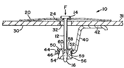
Figure 1 is a section view of the retainer
assembly of the present invention;
Figure 2 is a top view of the retainer assem-
bly;
Figure 3 is a section view of the xetainer
assembly being inserted into the receiving member; and
Figure 4 is a section view after the applying
force has been released from the head member of the re-
tainer assembly.
The retainer assembly of the present invention
is designated generally by reference numeral 10 in Figure
15 1. Retainer assembly 10 comprises a longitudinally extend-
ing retainer body 12 having an enlarged diameter or head
member 14 at one end and a flared member 16 disposed at
the other end. Retainer body 12 has the general appear-
ance of a nail with the flared member shaped like an
20 arrowhead. A resilient member 20 is generally a V-shaped
leaf spring (see Figure 2) and includes at the bottom of
the ~-shaped opening 22 a circular opening 24 which re-
ceives the retainer body. The resilient member 20 en-
gages retainer head member 14. Resilient member 20 in-
25 cludes resilient legs 25, 26, and 27. The brake shoe isshown in partial section as web portion or first member
30 which includes an opening 32. The backing plate or
second member 40 includes a first surface 42 disposed
axially apart from a second surface 44. Second surface
3~ 44 includes an opening 46 having a receiving member 50
disposed therein. Receiving member 50 is generally annu-
lar shaped and has an enlarged diameter head 52 extending
into a plurality of four fingers 54. Each finger 54 has
an outer circumferential surface 56 comprising a stepped
35 diameter which engages portions of the opening 46. Receiv-
ing member 50 further includes an interior passage 5~
which has a reduced interior diameter by means of radially
extending finger portions 59. Radially extending finger
I

13~
portions 59 are each associated with respective fingers
54. Each finger 54 is at-tached to the adjacent head 52
by a flexible connection 60. Flexible connections 60 per-
mit fingers 54 to be moved radially relative to one
another.
In order to assemble brake shoe web 30 into
engagement with first surface 42 of second member 40, the
retainer body is inserted into opening 22 of the resilient
member 20. Flared member 16 of assembly 10 is inserted
10 through opening 32 so that resilient member 20 is trapped
between the head member 14 and surface 31 of web 30. The
flared member is inserted through receiving member 50 dis-
posed in opening 46 of plate 40 wherein member 16 engages
finger portions 59 and spreads them radially apart (see
15 Figure 1). As flared member 16 passes through fingers 54,
the fingers rebound resiliently inwardly to snap into
engagement behind the flared member and trap the retainer
body between the receiving member and resilient member
(see Figure 3). The ~resilient member biases brake shoe
20 web or first member 30 into engagement with first surface
42 of the second member or backing plate 40. When the
applying force F (see Figure 3~ is relieved from head
member 14, stepped diameter circumference 56 engages por-
tions of opening 46 to move fingers 54 radially inwardly
25 as the receiving member 50 is displaced slightly axially
by body 12 and resilient member Z0 (see Figure 4). This
causes finger portions 59 to prevent removal of flared
member 16. Figure 4 illustrates the retainer assembly
after insertion when the applying force F has been
30 removed therefrom.
While the invention has been described with
respect to the detailed embodiment, it will be understood
that the invention is capable of numerous rearrangements,
modifications, and alterations, and such are intended to
35 be within the scope of ~he appended claims.

Representative Drawing
A single figure which represents the drawing illustrating the invention.
Administrative Status

2024-08-01:As part of the Next Generation Patents (NGP) transition, the Canadian Patents Database (CPD) now contains a more detailed Event History, which replicates the Event Log of our new back-office solution.

Please note that "Inactive:" events refers to events no longer in use in our new back-office solution.

For a clearer understanding of the status of the application/patent presented on this page, the site Disclaimer , as well as the definitions for Patent , Event History , Maintenance Fee  and Payment History  should be consulted.

Event History

Description Date
Inactive: IPC from MCD 2006-03-11
Time Limit for Reversal Expired 1997-05-20
Letter Sent 1996-05-20
Grant by Issuance 1992-05-19

Abandonment History

There is no abandonment history.

Owners on Record

Note: Records showing the ownership history in alphabetical order.

Current Owners on Record
ALLIED-SIGNAL INC.
Past Owners on Record
DONALD DIXON JOHANNESEN
ROBERT BRUCE TEMPLE
Past Owners that do not appear in the "Owners on Record" listing will appear in other documentation within the application.
Documents

To view selected files, please enter reCAPTCHA code :


To view images, click a link in the Document Description column. To download the documents, select one or more checkboxes in the first column and then click the "Download Selected in PDF format (Zip Archive)" or the "Download Selected as Single PDF" button.

List of published and non-published patent-specific documents on the CPD .

If you have any difficulty accessing content, you can call the Client Service Centre at 1-866-997-1936 or send them an e-mail at CIPO Client Service Centre.


Document
Description 
Date
(yyyy-mm-dd) 
Number of pages   Size of Image (KB) 
Cover Page 1993-10-30 1 12
Abstract 1993-10-30 1 27
Claims 1993-10-30 4 147
Drawings 1993-10-30 1 27
Representative Drawing 2003-03-19 1 11
Descriptions 1993-10-30 4 158
Fees 1994-04-18 1 68
Fees 1995-04-18 1 99