Sélection de la langue

Search

Sommaire du brevet 1301081 

Énoncé de désistement de responsabilité concernant l'information provenant de tiers

Une partie des informations de ce site Web a été fournie par des sources externes. Le gouvernement du Canada n'assume aucune responsabilité concernant la précision, l'actualité ou la fiabilité des informations fournies par les sources externes. Les utilisateurs qui désirent employer cette information devraient consulter directement la source des informations. Le contenu fourni par les sources externes n'est pas assujetti aux exigences sur les langues officielles, la protection des renseignements personnels et l'accessibilité.

Disponibilité de l'Abrégé et des Revendications

L'apparition de différences dans le texte et l'image des Revendications et de l'Abrégé dépend du moment auquel le document est publié. Les textes des Revendications et de l'Abrégé sont affichés :

  • lorsque la demande peut être examinée par le public;
  • lorsque le brevet est émis (délivrance).
(12) Brevet: (11) CA 1301081
(21) Numéro de la demande: 1301081
(54) Titre français: DISPOSITIF D'ARRET
(54) Titre anglais: RETAINER ASSEMBLY
Statut: Périmé et au-delà du délai pour l’annulation
Données bibliographiques
(51) Classification internationale des brevets (CIB):
  • F16D 65/08 (2006.01)
  • F16B 5/06 (2006.01)
  • F16B 21/07 (2006.01)
  • F16D 65/09 (2006.01)
(72) Inventeurs :
  • TEMPLE, ROBERT BRUCE (Etats-Unis d'Amérique)
  • JOHANNESEN, DONALD DIXON (Etats-Unis d'Amérique)
(73) Titulaires :
  • ALLIED-SIGNAL INC.
(71) Demandeurs :
  • ALLIED-SIGNAL INC. (Etats-Unis d'Amérique)
(74) Agent: MACRAE & CO.
(74) Co-agent:
(45) Délivré: 1992-05-19
(22) Date de dépôt: 1988-04-22
Licence disponible: S.O.
Cédé au domaine public: S.O.
(25) Langue des documents déposés: Anglais

Traité de coopération en matière de brevets (PCT): Non

(30) Données de priorité de la demande:
Numéro de la demande Pays / territoire Date
099,869 (Etats-Unis d'Amérique) 1987-09-22

Abrégés

Abrégé anglais


RETAINER ASSEMBLY
ABSTRACT OF THE DISCLOSURE
The retainer assembly (10) comprises a longi-
tudinally extending retainer body (12) having an enlarged
diameter or head member (14) at one end and an arrow-
shaped or flared member (16) at the other end. A V-shaped
leaf spring (20) has an opening (24) at the bottom of the
V-shaped opening (22) which receives the retainer body
(12) so that the spring (20) is disposed between the head
member (14) and a surface (31) of a first member (30). The
retainer body (12) extends through an opening (32) in the
first member (30) and the flared member (16) is resili-
ently captured within a resilient receiving member (50)
disposed within an opening (46) of the second member (40).
The opening (46) in the second member (40) is in a second
surface (44) disposed apart from a first surface (42) of
the second member (40) which engages the first member
(30). The receiving member (50) flexibly traps the flared
member (16) after insertion therethrough so that the leaf
spring (20) biases the first member (30) into engagement
with the second member (40).

Revendications

Note : Les revendications sont présentées dans la langue officielle dans laquelle elles ont été soumises.


THE EMBODIMENTS OF THE INVENTION IN WHICH AN EXCLUSIVE
PROPERTY OR PRIVILEGE IS CLAIMED ARE DEFINED AS FOLLOWS:
1. A retainer assembly for maintaining a first
member in engagement with a second member, comprising a
retainer body which extends longitudinally between a head
member at one end and a flared member at the other end, a
resilient member having an opening receiving the retainer
body and abutting the head member, the resilient member
disposed between said head member and a surface of the first
member so that the retainer body extends through an opening
in the first member, the second member having a pair of
surfaces spaced apart from one another and one of the pair
of surfaces having an opening, a receiving member disposed
within the opening in the second member and having a passage
therethrough, the receiving member gripping flexibly the
second member so that insertion of the flared member through
the passage in the receiving member causes the receiving
member to be deformed resiliently by the flared member and
then return toward an initial position wherein the receiving
member retains the retainer body by means of engagement with
the flared member, the resilient member biasing the head
member so that the flared member retracts slightly axially
the receiving member through the opening in the second member
to cause the receiving member to capture securely the flared
member, the receiving member including a stepped exterior
circumference which engages said opening in the second member
so that the slight axial retraction of the receiving member
through the opening in the second member causes the receiving
- 4 - 13177/rn

member to contract and engage more tightly the flared member,
and the retainer assembly biasing the first member into
engagement with the second member.
2. The retainer assembly in accordance with claim
1, wherein the receiving member includes at least one finger
portion extending radially inwardly into the passage to
provide a shoulder for engagement with said flared member.
3. The retainer assembly in accordance with claim
2, wherein the flared member comprises a substantially arrow-
shaped head.
4. The retainer assembly in accordance with claim
3, wherein the receiving member comprises a member divided
into quadrants, the quadrants connected via living hinge
connections.
5. The retainer assembly in accordance with claim
3, wherein the receiving member comprises a circular member
divided substantially into two halves and connected by a
living hinge.
6. The retainer assembly in accordance with claim
5, wherein the resilient member comprises a substantially V-
shaped leaf spring, the opening in the resilient member
comprising an opening at the bottom of a V-shaped opening in
the V-shaped leaf spring.
- 5 - 13177/rn

7. A retainer assembly for maintaining a first
member in abutting engagement with a second member, the
assembly extending between the members and biasing the
members into engagement with one another, characterized in
that the assembly comprises a retainer body which extends
longitudinally between a head member at one end and a flared
member at the other end, a resilient member having an opening
receiving the retainer body and abutting the head member, the
resilient member disposed between said head member and a
surface of the first member so that the retainer body extends
through an aligned opening in the first member, the second
member having a pair of surfaces spaced apart from one
another and one of the pair of surfaces having an opening,
a receiving member disposed within the opening in the second
member and having a passage therethrough, the receiving
member gripping flexibly the second member so that insertion
of the flared member through the passage in the receiving
member causes the receiving member to be deformed resiliently
by the flared member and then return toward an initial
position wherein the receiving member retains the retainer
body by means of engagement with the flared member, the
resilient member biasing the head member so that the flared
member moves slightly axially the receiving member through
the opening in the second member to cause the receiving
member to capture tightly the flared member, the receiving
member including a stepped exterior circumference which
engages said opening in the second member so that the slight
axial movement of the receiving member through the opening
- 6 - 13177/rn

in the second member causes the receiving member to engage
more tightly the flared member, and the retainer assembly
biasing the first member into abutting engagement with the
second member.
8. The retainer assembly in accordance with claim
7, characterized in that the receiving member includes
fingers extending radially inwardly into the passage to
provide shoulders for engagement with said flared member.
9. The retainer assembly in accordance with claim
7, characterized in that the flared member comprises a
substantially arrow-shaped head.
10. The retainer assembly in accordance with claim
7, characterized in that the receiving member comprises a
member divided into quadrants, the quadrants connected via
living hinge connections.
11. The retainer assembly in accordance with claim
7, characterized in that the receiving member comprises a
circular member divided substantially into two halves and
connected by a living hinge.
12. The retainer assembly in accordance with claim
11, characterized in that the resilient member comprises a
substantially V-shaped leaf spring, the opening in the
resilient member comprising an opening at the bottom of a V-
shaped opening in the V-shaped leaf spring.
- 7 - 13177/rn

Description

Note : Les descriptions sont présentées dans la langue officielle dans laquelle elles ont été soumises.

~. 30 ~ ~1 6~
RETAINER ASSEMBLY
This invention relates generally to a retainer
assembly for biasing resiliently a first member into
engagement with the second member, and in particular to a
retainer which biases a brake shoe web into engagement with
a backing plate.
Many drum brakes are equipped with shoe hold-down
retainers which maintain the brake shoes in engagement with
the backing plate of the drum brake. The web of each brake
shoe is biased into engagement with the backing plate by
means of the retainer assembly. Many such retainer
assemblies have been proposed in the prior art, and it is
desirable to provide a retainer assembly that may be easily
assembled from the shoe side of the backing plate, which has
a minimum number of parts, and which is inexpensively
manufactured and easily assembled.
The present invention provides a solution to the
above, in that the retainer assembly maintains a first member
in engagement with a second member, and comprises a retainer
body which extends longitudinally between a head member at
one end and a flared member at the other end, a resilient
member having an opening receiving the retainer body and
abutting the head m~mber, the resilient member disposed
between the head member and a surface of the first member so
that the retainer body extends through an opening in the
first member, the second member having a pair of surfaces
~, ~ r~ 3177/rll

~.~Q~
la
spaced apart from one another and one of the pair of surfaces
having an opening, a receiving member disposed within the
opening in the second member and having a passage
therethrough, the receiving member gripping flexibly the
second member so that insertion of the flared member through
the passage in the receiving member causes the receiving
membex to be deformed resiliently by the flared member and
then return toward an initial position wherein the receiving
member retains the retainer body by means of engagement with
the flared member, the resilient member hiasing the head
member so that the flared member retracts slightly axially
the receiving member through the opening in the second member
to cause the receiving member to capture securely the flared
member, the receiving member including a stepped exterior
circumferenGe which engages the opening in the second member
so that the slight axial retraction of the receiving member
through the opening in the second member causes the receiving
member to contract and engage more tightly the flared member,
and the retainer assembly biasing the first member into
engagement with the second member.
~ r~
.,.. Al, ~
~. ~ . ~.
13177/rn

One way of carrying out the invention is des-
cribed in detail below with reference to the drawings
which illustrate an embodiment, in which:
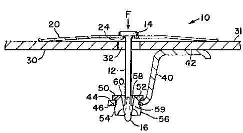
Figure 1 is a section view of the retainer
assembly of the present invention;
Figure 2 is a top view of the retainer assem-
bly;
Figure 3 is a section view of the xetainer
assembly being inserted into the receiving member; and
Figure 4 is a section view after the applying
force has been released from the head member of the re-
tainer assembly.
The retainer assembly of the present invention
is designated generally by reference numeral 10 in Figure
15 1. Retainer assembly 10 comprises a longitudinally extend-
ing retainer body 12 having an enlarged diameter or head
member 14 at one end and a flared member 16 disposed at
the other end. Retainer body 12 has the general appear-
ance of a nail with the flared member shaped like an
20 arrowhead. A resilient member 20 is generally a V-shaped
leaf spring (see Figure 2) and includes at the bottom of
the ~-shaped opening 22 a circular opening 24 which re-
ceives the retainer body. The resilient member 20 en-
gages retainer head member 14. Resilient member 20 in-
25 cludes resilient legs 25, 26, and 27. The brake shoe isshown in partial section as web portion or first member
30 which includes an opening 32. The backing plate or
second member 40 includes a first surface 42 disposed
axially apart from a second surface 44. Second surface
3~ 44 includes an opening 46 having a receiving member 50
disposed therein. Receiving member 50 is generally annu-
lar shaped and has an enlarged diameter head 52 extending
into a plurality of four fingers 54. Each finger 54 has
an outer circumferential surface 56 comprising a stepped
35 diameter which engages portions of the opening 46. Receiv-
ing member 50 further includes an interior passage 5~
which has a reduced interior diameter by means of radially
extending finger portions 59. Radially extending finger
I

13~
portions 59 are each associated with respective fingers
54. Each finger 54 is at-tached to the adjacent head 52
by a flexible connection 60. Flexible connections 60 per-
mit fingers 54 to be moved radially relative to one
another.
In order to assemble brake shoe web 30 into
engagement with first surface 42 of second member 40, the
retainer body is inserted into opening 22 of the resilient
member 20. Flared member 16 of assembly 10 is inserted
10 through opening 32 so that resilient member 20 is trapped
between the head member 14 and surface 31 of web 30. The
flared member is inserted through receiving member 50 dis-
posed in opening 46 of plate 40 wherein member 16 engages
finger portions 59 and spreads them radially apart (see
15 Figure 1). As flared member 16 passes through fingers 54,
the fingers rebound resiliently inwardly to snap into
engagement behind the flared member and trap the retainer
body between the receiving member and resilient member
(see Figure 3). The ~resilient member biases brake shoe
20 web or first member 30 into engagement with first surface
42 of the second member or backing plate 40. When the
applying force F (see Figure 3~ is relieved from head
member 14, stepped diameter circumference 56 engages por-
tions of opening 46 to move fingers 54 radially inwardly
25 as the receiving member 50 is displaced slightly axially
by body 12 and resilient member Z0 (see Figure 4). This
causes finger portions 59 to prevent removal of flared
member 16. Figure 4 illustrates the retainer assembly
after insertion when the applying force F has been
30 removed therefrom.
While the invention has been described with
respect to the detailed embodiment, it will be understood
that the invention is capable of numerous rearrangements,
modifications, and alterations, and such are intended to
35 be within the scope of ~he appended claims.

Dessin représentatif
Une figure unique qui représente un dessin illustrant l'invention.
États administratifs

2024-08-01 : Dans le cadre de la transition vers les Brevets de nouvelle génération (BNG), la base de données sur les brevets canadiens (BDBC) contient désormais un Historique d'événement plus détaillé, qui reproduit le Journal des événements de notre nouvelle solution interne.

Veuillez noter que les événements débutant par « Inactive : » se réfèrent à des événements qui ne sont plus utilisés dans notre nouvelle solution interne.

Pour une meilleure compréhension de l'état de la demande ou brevet qui figure sur cette page, la rubrique Mise en garde , et les descriptions de Brevet , Historique d'événement , Taxes périodiques et Historique des paiements devraient être consultées.

Historique d'événement

Description Date
Inactive : CIB de MCD 2006-03-11
Le délai pour l'annulation est expiré 1997-05-20
Lettre envoyée 1996-05-20
Accordé par délivrance 1992-05-19

Historique d'abandonnement

Il n'y a pas d'historique d'abandonnement

Titulaires au dossier

Les titulaires actuels et antérieures au dossier sont affichés en ordre alphabétique.

Titulaires actuels au dossier
ALLIED-SIGNAL INC.
Titulaires antérieures au dossier
DONALD DIXON JOHANNESEN
ROBERT BRUCE TEMPLE
Les propriétaires antérieurs qui ne figurent pas dans la liste des « Propriétaires au dossier » apparaîtront dans d'autres documents au dossier.
Documents

Pour visionner les fichiers sélectionnés, entrer le code reCAPTCHA :


Pour visualiser une image, cliquer sur un lien dans la colonne description du document. Pour télécharger l'image (les images), cliquer l'une ou plusieurs cases à cocher dans la première colonne et ensuite cliquer sur le bouton "Télécharger sélection en format PDF (archive Zip)" ou le bouton "Télécharger sélection (en un fichier PDF fusionné)".

Liste des documents de brevet publiés et non publiés sur la BDBC .

Si vous avez des difficultés à accéder au contenu, veuillez communiquer avec le Centre de services à la clientèle au 1-866-997-1936, ou envoyer un courriel au Centre de service à la clientèle de l'OPIC.


Description du
Document 
Date
(aaaa-mm-jj) 
Nombre de pages   Taille de l'image (Ko) 
Page couverture 1993-10-30 1 12
Abrégé 1993-10-30 1 27
Revendications 1993-10-30 4 147
Dessins 1993-10-30 1 27
Dessins représentatifs 2003-03-19 1 11
Description 1993-10-30 4 158
Taxes 1994-04-18 1 68
Taxes 1995-04-18 1 99