Note: Descriptions are shown in the official language in which they were submitted.
~3V~J~;
--1--
METHOD AND SYSTEM FOR TREATING A
PRODUCED HYDROCARBON-CONTAINING FLUID
FIELD OF THE INVENTION
The invention relates generally to methods a~d
apparatus for treating produced, hydrocarbon-containing fluids.
More particularly, the invention relates to methods and
apparatus for reducing the oil concentration of produced,
hydrocarbon-containing fluids and softening the resulting
deoiled fluids to reduce scale-forming constituents.
BACKGROUND OF THE INV~TION
There are a variety of hydrocarbon extraction processes
for producing hydrocarbon-containing fluids. Typ;cally9 the
produced fluids are emulsions including both hydrocarbons and
"hard water," where the phrase "hard water" denotes water having
impurities that form insoluble precipitates known as "scale"
when the hard water is heated. It is desirable to separate the
produced, hydrocarbon-containing fluids into a predominantly
-, liquid hydrocarbon portion, a predominantly liquid water
portion, and a gaseous portion. The predominantly liquid water
portion will typically include hard water.
':.,
" ~
~L3~
For many applications, it is desirable to "soften" the
liquid water portion by decreasing substantially the
concentration of impurities (generally, these are divalent metal
ions) in the hard water which can form insoluble precipitates.
One suitable technique for softening hard water is the thermal
softening process described in U.S. Patent 4,518,505, issued
May 21, 1985 to G. B. Lim and A. R. Konak, and assigned to Exxon
Production Research Company. A system for processing a fluid in
accordance with the thermal softening process disclosed in such
patent will be referred to herein as a "thenmal softening
unit."
For many applications, it is desirable not only to
soEten the liquid water portion of the produced fluid but to
reduce substantially the concentration of hydrocarbons in the
liquid water portion. The concentration of hydrocarbons in a
fluid will hereinafter be referred to as the "oil concentration"
of the fluid and will be quantified in units of parts per
million ("ppm").
In one important example, a bitumen-containing emulsion
is extracted from a tar sand formation using a conventional
cyclic steam stimulation process. Steam, typlcally having
quality of about 80%, is injected into the formation to mobilize
bitumen which is subsequently produced with the steam condensate
as emulsion. This emulsion typically contains 3 to 4 volumes of
water for each volume of bitumen and its temperature is
approximately 140C once the steady state conditions are
established. The emulsion is typically first cooled to around
~L3~
125C to recover some of its heat and raise boiler feedwater
temperature from approximately 100C to appro~imately 133C .
It is then separated in an inlet separator into its gas~ oil and
water co~ponents at about 125C. The inlet separator thus acts
as an initial separator. Also the inlet separator takes up the
production surges that frequently occur in this type of steam
stimulation operation. Most of the free water (up to 75~ or
more) is separated from the hydrocarbon and gas components by
the inlet separator. The bitumen along with the remaining
liquid water is separated into approximately equal streams for
further cooling and treatment at two or more free and emulsified
water removal units. Bitumen with a bottom sediment and water
specification (BS & W specification) of 1/2% or less emerges
from~these units for blending with diluent prior to pipelining.
A water stream emerges from each free water removal unit at
around 110C and is further cooled and combined ~ith the water
stream emerging from the inlet separator~ and the combined
stream is further cooled prior to storage and further oil
separation at atmospheric pressure. The oil content of the
combined water stream is typically approximately 1% to 5%. Some
of the oil is skimmed off in a skim tank and is recycled. The
water, at 80-90C, is then further treated by induced gas
floatation and coalescing filters to reduc~ its oil
concentration to 10 ppm or less before the deoiled water is
softened in a hot lime treater (HLT) and then filtered by
anthracite filters. Remaining traces of hardness are removed in
a set of ion exchange units and the deoiled, softened water is
then stored in a boiler feedwater tank. Deoi]ed, softened water
13~
.
from this tank is beat exchanged with the inlet production to
recover some of the heat as mentioned earlier, and then is fed
to a boiler for steam generation purposes. Also make up fresh
water used in the HLT is heated up using a portion of the heat
recovered from the inlet production.
It is emphasized that the conventional syste~ described
above, and similar conventionai systems, employ heat exchangers
to extract heat from the produced fluid either before the fluid
is separated into its components or after various components
have been separated fronl it (or both before and after
separation) for the purpose of transferrîng the extracted heat
to boiler feed water while reducing the fluid temperature to
about 80-90C, to facilitate deoiling at about 80-9OaC and
atmospheric pressure.
The conventional system described above has several
drawbacks. First, the produced fluid, or the predominantly
liquid water component thereof, needs to be cooled down and
heated up again to deoil and soften it. Second, not all the
heat can be recovered and used in the system and excess heat is
dissipated to atmosphere. Third, the steam generation
Eacilities are coupled with bitumen production facilities
through the heat exchanger that heats up the boiler feedwater
and cools down the inlet production. Therefore wben one
facility is upset, the other is affected. Fourth, the water
reuse system is complex and entails large capital and opesatin~
costs.
~3~
- 5 - ~
Here disclosed is a method and system for treating a produced,
hydrocarbon-containing fluîd having temperature greater than 100C within
typically the range of approximately 120C to approximately 160C. The
method includes the steps of reducing the oil concentration of the fluid
to a level appropriate for processing in a thermal softening unit
(typically no more than approximately 10 ppm), and softeni.ng the deoiled
fluid in the thermal softening unit. In a preferred embodiment, the
deoiled fluid will not only be softened in the thermal softening unit, but
will also undergo filtration in the thermal softening unit to reduce the
amount of associated solid impurities and will thereafter be processed in
a steam generation unit. This embodiment is useful, for example, where
the produced fluid is an emulsion containing hard water and bitumen
produced as a result of cyclic steam stimulation of a tar sand formation.
The steam produced in the steam generation unit may be rejected into the
formation for stimulation purposes.
The new system is capable of performing the new methodl and
includes a hot deoiling unit and a thermAl softening unit. The hot
deoiling unit and thermal soEtening unit are each capable oE treating
produced, hydrocarbon-containing fluids having temperature greater than
100C, typically within the range of approximately 120C to approximately
160C.
The new method has the following advantage over conventional
methods for treating produced fluids having temperature in the approximate
range of 120C-160C. It eliminates the need to employ heat exchanges for
reducing the temperature of the produced fluids and for attempting to
transfer heat from the produced fluids to recycle water. Elimination of
such heat exchangers improves the energy efficiency of the overall fluid
treatment and water recycling process, and simplifies the process by
reducing equipment requirements.
The new method also provides greater flexibility by decoupling the
steam generation unit from the portion of the system in which hydrocarbons
are separated from the raw produced fluids, in contrast with coupling them
through heat exchanger units. Overall, performance of the new method
should reduce capital and operating costs, reduce chemical usage and
....
3~
- 5a -
handling, and increase energy efficiency relative to conventional produced
fluid treatment processes.
More particularly in accordance with a first aspect of the
invention there is provided a method for treating a hot produced
S hydrocarbon-containing fluid having a temperature greater than 100C
comprising the steps of:
(a) flowing the hot produced fluid, without substantial removal of
heat, to an inlet separator;
(b) separating the hot produced fluid in the inlet separator into
a predominantly gaseous portion, a predominantly liquid hydrocarbon
portion, and a predominantly liquid water portion;
(c) flowi.ng the predominantly liquid water portion, without
substantial removal of heat, to a hot deoiling unit;
(d) reducing the oil concentration of the predominantly liquid
lS water portion in the hot deoiling unit to a level appropriate for
processi.ng in a thermal softening unit, thereby deoiling the predominantly
liquid water portion; and
(e) soEtening the deoiled liquid water portion in a thermal
softening unit.
In accordance with the second aspect of the invention there is
provided, a method for treating a hot produced hydrocarbon-containing
fluid having a temperature greater than 100C comprising the steps of:
(a) flowing the hot produced fluid, without substantial removal of
heat, into an inlet separator;
(b) separating the hot produced fluid in the inlet separator into
a first, predominantly gaseous portion; a second portion consisting
predominantly of liquid hydrocarbon; and a third portion consisting
predominantly of liquid water;
(c) separating the second portion into a fourth portion consistlng
predominantly of liquid hydrocarbon and a fifth portion consisting
predominantly of liquid water;
(d) combining the fifth portion with the third portion to produce
a combined portion having a temperature within the range of approximately
120C to approximately 160C and oil concentration within the range of
approximately 1% to approximately 5%;
~3~L~L~5
- 5b -
(e) flowing the combined portion, without substantial removal of
heat, to a hot deoiling unit;
(f) reducing the hot concentration of the combined portion in the
hot deoiling unit to a level appropriate for processing in a thermal
softening unit, thereby deoiling the predominantly liquid water portion,
wherein the deoiled combined portion has a temperature within the range of
approximately 120C to approximately 160C; and
(g) softening the deoiled combined portion in a ther~al softening
unit wherein the softened, deoiled combined portion has a temperature
within the range of approximately 180C to approximately 210C.
In accordance with a thi~d aspect of the invention there is
provided a method for treating a hot produced hydrocarbon-containing fluid
having a temperature greater than 100C comprising the steps of:
(a) flowing the hot produced fluid, without substantial removal of
heat, to an inlet separator;
(b) separating the hot produced iluid in the inlet separator into a
first, predominantly gaseous portion: a second portion consisting
predomlnantly of liquid hydrocarbon: and a third portion consisting
pre~ominantly of liqùid water having an oil concentration within the range of
approximately la to approximately 5~:
(c) cooling the second portion to about 110 C;
(d) separating the second portion into a fourth portion consisting
predominantly of liquid hydrocarbon and a fifth portion consisting
predominantly of liquid water having an oil concentration within the range of
approximately 1~ to approximately 5~;
(e) combining the flfth portion with the third portion to produce a
combined portion having a temperature within the range of approximately 120 C
to approximately 160 C and an oil concentration within the range of
approximately 1~ to approximately 5~:
(f) flowing the combined portion, without substantial removal of
heat, to a hot deoiling unit;
(g) reducing the oil concentration of the combined portion in the
hot deoiling unit to a level appropriate for processing in a thermal softening
unit, thereby deoiling the predominantl.y liquid water portion, wherein the
deoiled combined portion has a temperature within the range of approximately
120 C to approximately 160 C,
~L3~
(h) flowing the deoiled combined portion, without substantial
removal of heat, to,a reaction zone:
(i) heating, within the reaction zone, the deoiled combined portion
by sparging with steam to a temperature within the range of approximately
150 C to approximately 250 C to facilitate so~tèning of the deoiled combined
portion;
(j) withdrawing the softened, deoiled combined portion from the
reaction zone;
(~) flowing the softened, deoiled combined portion to a filtration
unit, without substantial removal of heat; and
(1) filtering scale from the softened, deoiled, combined portion in
the filtration unit.
In accordance with a fourth aspect of the invention there is
provided a system for treating a produced, hydrocarbon-containing fluid
having a temperature within the range from approximately 120C to
approximately 160C, including:
a hot deoiling unit capable of reducing the oil concentration of
the fluid to no more than approximately 10 ppm; and
a thermal softening unit in fluid communication with the hot
deoiling unit.
Embodiments of the invention will now be described with reference
to the accompanying drawings wherein:
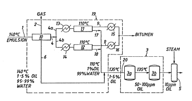
FIGURE 1 is a schematic diagram of a preferred embodiment of the
inventive system.
FIGURE 2 is a schematic diagram of a preferred embodiment of
thermal softening unit 5 of the FIGURE 1 system.
DETAILED DESCRIPTION OF THE PREFERRED EMBODIMENTS
Reference will now be made to FIGURE 1, which schematically shows a
preferred embodiment of the inventive system. A hot,
hydrocarbon-containing produced fluid (identified by numeral 1) flows into
inlet separator 10. The output of separator 10 includes three portions: a
.,
,
,
predominantly gaseous portion 2; a portion (identified by
numeral 4) which consists predominantly of liquid hydrocarbons;
and a portion (identified by numeral 6) which consists
predominantly of liquid water.
ne~
The if'Y~tfe system is capable of treating produced,
r~
hydrocarbon-containing fluids havlng temperature within the
range from approximately lZ0C to approximately 160C. For
purposes of describing FIGURE 1, fluid 1 will be described as an
emulsion, having temperature about 140C, of bitumen and steam
condensate (hard water) produced as a result of cyclic steam
stimulation of a tar sand formation, though the FIGURE 1 system
or variations of the system, may be used to treat other
produced, hydrocarbon-containing fluids having temperature in
the described range. For example, hydrocarbon-containing fluids
may be produced as a result of application of any of a variety
of thermal processes, such as steam flooding, fire flooding, as
well as steam stimulation, to subterranean formation.
Typically, such a bitumen steam condensate emulsion will have 3
to 4 volumes of condensate for each volume of bitumen. Inlet
separator 10 acts as an initial separator and also takes up
.~ :
production surges that commonly occur in hydrocarbon extraction
operations. Inlet separator 10 may be selected from those
commercially available ~hich are capable of separating fluid
into portions 2, 4, and 6 in such a manner that the temperature
of portions 2, 4 and 6 is not significantly reduced relative to
the temperature of fluid 1, and so that portions 4 and 6 have
sufficiently high pressure so that they may be maintained in
liquid form for subsequent processing. Inlet separator lO will
~L3~
--8-- .
preferably have sufficiently large capacity so that the
composition of portion 6 will be predominantly liquid water,
with an oil concentration of about 1% at most times during
operation o~ the system, and with occasional surges in oil
concentration up to no more than about 57O.
Portion 4 is divided into subportions 4a and 4b for
subsequent processing to separate the bitumen components from
the oily water component thereof. Although portion ~ is shown
to be split into two subportions in FIGUR~ 1, it ~s within the
scope of the invention to split portion 4 into any number o~
subportions, or to refrain from splitting portion 4 at all prior
to subsequent treatment. Subportions 4a and 4b are cooled by
heat exchangers 13 and 14, respectively, to about 110C for
treatment in water removal units 11 and 12. Bitumen 9 emerges
from each water removal unit and passes through heat
exchangers 15 and 16. Also, water stream 17 emerges from water
removal unit 11 and water stream 18 emerges from water removal
unit 12. Streams 17 and 18 each have temperature approximately
. .
equal to 110C and include hard water with an oil concentration
I of approximately l~o. Streams 17 and 18 are combined with
portion 6 to form combined stream 20. Combined stream 20 has
temperature approximately equal to 135C and has oil
concentration in the range 1-5%. It should b~ recognized that
the temperature of combined stream 2G will depend on ~he
temperature of fluid 1, and that of water streams 17 and 18, as
~3~ 5
well as on the relative volumes of portion 6 and streams 17
and 18. However, in all embodiments of the invention, the
temperature of combined stream 20 will be within the appro~imate
range 120C-160C.
Combined stream 20 is processed in hot deoiling unit 3
to reduce its oil concentration to no more than approximatFly
10 ppm. In the embodiment shown in FIGURE 1, hot deoiling
unit 3 includes two sets of coalescing filters, 3a and 3b.
Set 3a of coalescing filters reduces the oil concentration oE
combined stream 20 to approximately 50-100 ppm, and set 3b of
coalescing filters further reduces the oil concentration to no
more than approximately 10 ppm. The coalescing filters may be
selected from those commercially available that are capable of
processing pressurized hydrocarbon-containing fluids having
temperature in the range of approximately 120C-160C, and may
be of the upflow type or the downflow type, or a combination of
both types. Set 3a of filters may be identical to set 3b.
Alternatively, a suitable hot deoiling unit 3 may be selected
from those commercially available membrane filters. In another
-- - alternative embodlment, either or both of sets 3a and 3b may be
replaced by a commercially available induced static gas
flotation unit working under appropriate pressure. Suitable
units of this type are manufactured by L'~au Claire Systems
Inc., of Louislana.
In yet another embodiment a hydrocyclone may precede
- either an induced gas flotation unit or a set of coalescing
Eilter~ to reduce gro:s amount~ oE oil.
~ 10 --
The deoiled fluid emerging from hot deoiling unit 3 is softened in
thermal softening unit 5. Thermal softening unit 5 wlll be described in
detail below with reference to FIGURE 2. Additional detail reBarding
~ariat~ons on the deslgn of thermal softening unit 5 is set forth in
5 above-rPferenced U.S. Patent 4,518,505.
The softened, deoiled fluid emerging from thermal softening unit 5 is
in liquid form and may be used for- a variety of purposes, such as injection
into a well for subterranean formation stimulation purposes. The
temperature of the fluid output from unit 5 will typically be in the range
18G-210C.
FIGURE 2 is a schematic diagram showing a preferred embodiment of
thermal softening unit 5. The deoiled fluid (sometimes referred to below
with reference to FIGURE 2 as "feed water" or "produced water") emerging
from hot deoiling unit 3 i9 pumped by pump 10~ via line 106 to a suitable
1~ reaction zone 110 where it is heated by steam issuing from a sparger 111.
Feed water is kept at a constant rate by a control valve 108 with signals
from a flow sensor 109 supplied to control valve 108 via broken line 109a.
In the embodiment shown feed water is introduced to reaction zone 110 from
the bottom and withdrawn from the top. This flow configuration allows
bet~er utilization of the entire in~ernal space of the vessel for reactions
and requires ~o level control. It also reduces the gaseous C02 accumulation
in the vessel.
.~
~ ..
~3~
Sparger 111 may be a perforated pipe coiled to cover a
substantial volume of reaction vessel 110. The coiled pipe is
perforated so that the steam is sparged downwardly into the
water, thus avoiding plugging of the perforations by scale
precipitates and ensuring good contact of the water by the
steam.
Reaction vessel 110 is equipped with temperature and
pressure sensors 114 and 115, respectively. The output from
temperature sensor 114 controls through broken line lll~a the
actuator of a valve 112 located in the steam input l;ne 113.
Thus, in the embodiment illustratedt the steam flow to the
sparger is controlled in response to temperature to maintain the
temperature within the reaction vessel 110 at a desired level.
It will be recognized of course that other suitable means for
steam flow control can be utilized. For example, the steam
input into the sparger can be controlled manually, in response
to pressure, or in response to the input rate of the feed water,
all by means which will be apparent to those of ordinary skill
in the art.
Within vessel 110 the feedwater is heated to the - ---
desired temperature ~which typically will be approximately
200C) and then withdrawn via line 116 and passed to a
filtration unit 117 for removing solids therefrom. Filtration
unit 117 may be of any suitable type, such as pro~ided by one or
more packed columns, screens, etc. A suitable filtration unit
may comprise one or more cartridge filters made from porous
metal membranes, and the retained precipitates may be backwashed
~L3~
- 12 -
by reducing the outlet pressure. One suitable filtration unit is
manufactured by Pall Inc. As the water effluent is being filtered through
one filter vessel, another filter vessel or vessels ~not shown) can be
backwashed to re~ove the precipitated scale.
The filtrate from filtration unit 117 is withdrawn via line 128 through
a pressure controlled valve 129. In the embodiment shown a portion of the
hot wa~er may be permitted to flow-into line 131 through valve 130 for
subsequent processing or use, such as in~ection into a hot water in~ection
well (not shown). A portion of the Pilter effluent flows through line 133
through valve 132 to boiler 136. Part of the steam produced within boiler
136 i9 withdrawn via line 137 (and may be applied to one or more injection
~ells) and the remainder is withdrawn via line 113 and employed in the
sparging step. It will be appreciated that in a variation on the embodiment
shown in FIGURE 2, steam input line 113 may not be connected to boiler 136,
but instead ~ay be connected to some other independent steam source ~not
shown in FIGURE 2). It is also within the scope of the invention for
filtration unit 117 to be absent, so that fluid in line 116 will flow
directly to line 128.
It ls preferred to e~ploy low pressure steam ~n the sparging step.
To generate low pressure steam for this purpose, pump 134 delivers soft
produced water through specially modified boiler economizer tubes
at a di~charge pressure between about 300 and 500 psi. These low
:~L3~ 5
pressure tubes should be independent of the other usual
economiæer tubes, which are normally operated at higher
pressures, e.g., on the order of several thousand psi, the high
pressure being maintained by the discharge pressure of the feed
pump 135.
As described above, the pressure in reaction vessel 110
is maintained at a value above the steam saturation pressure at
the temperature involved. It is also desirable to keep the
temperature differential between the reaction zone output and
the filtration unit at a minimum. For example, where the
temperature of the water withdrawn from the reaction vessel is
200C, the pressure may be maintained at a value of 300 psig.
The decrease in temperature between the heating vessel and the
I5 filtration unit usually can be kept to a value of less than
10C, with the pressure differential between the heating vessel
and the filtration unit normally falling within the range of
5-30 psi. Preferably, the filtering step is carried out at a
pressure which is greater than the water vapor pressure
corresponding to the temperature in the reaction vessel to
~-- prevent boiling.
The desired pressure in the heating vessel llO:can be
maintained by pressure sensors 115 which applies signals as
indicated by broken lines 115a to the controller for valve 129.
The controller responds to produce a control function to
regulate the effluent from filtration unit 117 by valve 129 to
maintain the desired pressure in unit 110. It will be
recogniæed that other suitable means may be employed to regulate
:L3r3~ S
-14-
the fluid flow from reaction zone 110. For example, ~alve 129
may be operated solely in response to the pressure in the
filtration effluent line without regard to pressure within
J vessel iiO ur i~ may be operat~ in res~orl~ ,o tile presSure a.
the input to the filtration unit.
The filtration unit is taken out of service for
backwash once the differential pressure reaches a certain ~alue,
usually 30 psig. For this purpose, pressure sensors 118 and 119
measure the pressure gradient across the filtration unit 117 and
send signals throllgh the broken }ines 118a and 119a respectively
to controller 120. When the pressure differential reaches the
preset value, e.g. 30 psig, the controller will trigger a
backwash on the filtration unit 117. Such systems for alternate
filtering and backwashing are well known in the art and no
further description need be provtded. Water for the backwash,
may be taken from the stream of deoiled fluid emerging from
unit 3 via line 122, and disposed of through line 127.
Alternatively, water for backwash may be taken from an
independent supply (not shown) to which line 122 is attached.
It is recognized that other backwash schemes can also be
applied; e.g., a portion of the soft produced water from other
filtration units in service could be used to flush the unit
taken offline for backwash. In that case, no backwash pump
would be necessary, as the pressure of the soft produced water
is believed sufficiently high to backwash the filter nedium.
1,
\
~3~
--15--
A certain amount o~ soft water is required initally to
produce steam by boiler 136 and to start up the softening
process. Such soft water is stored in tank 139 and withdrawn as
needed through line 142, check valve 141, and line 140 for use
in the start-up process.
Once the boiler and the softening process are n steady
operation, the inventory of t~nk 139 can be replenished by
taking a portion of soft water from the filtration unit 117 to
tank 139 through line 143, valve 144 and cooler 145 which cools
the soft water to prevent vaporization from taking place once
the water pressure is relieved to atmospheric pressure in
tank 139. Alternatively, this tank may be pressurized, and the
tank may be either in-line or off-line as desired.
It is understood that the flue gas leav;ng the
economizer of boiler 136 is substantially hotter than the boiler
feed water temperature, i.e. 200C, and carries with it a
certain amount of waste heat. To increase the boiler
efficiency, it is desirable to cool the flue gas to 100-150C
range by using it to preheat the boiler combustion air with an
air heater not shown in FIG. 2. ~eating the air before the
combustion will reduce boiler fuel consumption and m2ke the
process very energy efficient.
The relative amounts of feed water and sparging steam
applied to reaction vessel 110 will vary depending upon the feed
water temperature and the desired effluent temperature as well
as the steam temperature and quality. As a practical matter,
the feed water rate to the reaction zone usually will be about
2.5 times the s~eam flow rate on a weight basis.
~3~
-16-
It is sometimes desirable to add a base and magnesium
compound to the feed water. These chemicals can be added to the
feed water stream via line 13S.
Inlet separator 10, heat e~changers 13-16, and water
removal units 11 and 12, shown in FIGUR~ 1, may be selected from
suitable commercially availab}e units. The portion of the
FIGURE 1 system including separator 10, heat exchangers 13-16,
water removal units 11 and 12, and the fluid flow lines
connected thereto may be collectively referred to as hydrocarbon
separation subsystem 19. It is specifically contemplated that
other techniques of hydrocarbon separation besides that
described above may be performed preliminary to processing in
hot deoiling unit 3. Indeed, it is not an essential feature of
the invention that a subsystem 19 be provided. Rather, it is
also within the scope of the invention to treat produced
hydrocarbon-containing fluids having temperature in the
approximate range 120C-160C using only hot deoiling unit 3 and
thermal processing unit 5. Any of the above-described
embodiments of hot deoiling unit 3 and thermal processing unit 5
may be employed.
; In addition to the bitumen-containing emulsion
described above with reference to FIGURE 1, e.Yamples of produced
fluids that may be processed in accordance with the inventive
technique include emulsions of water and hea~y oil with an API
gravity in the range from 9 to 20.
-
13~ 5
-17
The above description is merely illustrative of the
invention. It is contemplated that various changes in the
details of the structures and methods described maY be within
the scope of the invention as defined by the appended claims.
:,
.,1 , .
. "
~ 15
.
. ~ .
. ,, ~
."`