Language selection

Search

Patent 1301208 Summary

Third-party information liability

Some of the information on this Web page has been provided by external sources. The Government of Canada is not responsible for the accuracy, reliability or currency of the information supplied by external sources. Users wishing to rely upon this information should consult directly with the source of the information. Content provided by external sources is not subject to official languages, privacy and accessibility requirements.

Claims and Abstract availability

Any discrepancies in the text and image of the Claims and Abstract are due to differing posting times. Text of the Claims and Abstract are posted:

  • At the time the application is open to public inspection;
  • At the time of issue of the patent (grant).
(12) Patent: (11) CA 1301208
(21) Application Number: 531737
(54) English Title: HIGH PRESSURE ROTARY SHAFT SEAL
(54) French Title: JOINT ETANCHE AUX PRESSIONS ELEVEES SUR ARBRE TOURNANT
Status: Deemed expired
Bibliographic Data
(52) Canadian Patent Classification (CPC):
  • 277/40
(51) International Patent Classification (IPC):
  • F16J 15/26 (2006.01)
  • F16J 15/18 (2006.01)
(72) Inventors :
  • ZITTING, GORDON TREE (United States of America)
  • DUKE, JAY THOMAS (United States of America)
(73) Owners :
  • MACROTECH POLYSEAL, INC. (United States of America)
(71) Applicants :
(74) Agent: MACRAE & CO.
(74) Associate agent:
(45) Issued: 1992-05-19
(22) Filed Date: 1987-03-11
Availability of licence: N/A
(25) Language of filing: English

Patent Cooperation Treaty (PCT): No

(30) Application Priority Data:
Application No. Country/Territory Date
853,879 United States of America 1986-04-21

Abstracts

English Abstract


ABSTRACT

A seal assembly for a shaft comprises one or
more annular sealing elements having an initial inter-
nal diameter larger than the diameter of the shaft.
The elements are deformed by a pair of annular backup
rings disposed on opposite sides thereof. The backup
rings have opposed axially extending undulations
therein for effecting axial deformation and radial
contraction of the sealing elements upon advancement of
the backup rings toward one another.


Claims

Note: Claims are shown in the official language in which they were submitted.

THE EMBODIMENTS OF THE INVENTION IN WHICH AN EXCLUSIVE
PROPERTY OR PRIVILEGE IS CLAIMED ARE DEFINED AS FOLLOWS:
1. A seal assembly for a shaft extending through a
bore in a housing, said seal assembly comprising:
an axially compressible, radially expandable annular
shaft sealing means having an initial internal diameter equal
to or larger than the diameter of said shaft;
a pair of annular relatively hard inflexible backup
rings disposed on opposite sides of said shaft sealing means,
said backup rings having opposed axially extending undulations
therein undulating along the circumference of the rings from
one portion of the circumference to another for effecting
axial deformation and radial expansion of said shaft sealing
means upon advancement of said backup rings toward one
another; and
means connecting said backup rings to effect movement
thereof toward one another.
2. A seal assembly in accordance with claim 1
including an annular bore sealing ring disposed about said
shaft sealing means in radial alignment therewith, said bore
sealing ring being axially compressible by said backup rings
so as to be radially expandable against said bore and shaft
sealing means, respectively, and
a pair of retaining rings disposed between said
backup rings and on opposite sides axially of said bore
sealing ring, said retaining rings have axially extending
undulations therein, respectively, that effect radial
expansion of said retaining rings and engagement thereof with
said housing within the bore upon compression of said
undulations.


3. A seal assembly in accordance with claim 1
including a pair of retainer rings disposed between said
backup rings and having compressible axially facing undulating
radial face portions and radially facing relatively sharp edge
portions that are radially expandable into biting engagement
with said housing within the bore, said retaining rings being
disposed on opposite sides axially of said seal means to
stabilize said seal element against axial movement relative to
said housing.
4. A seal assembly for a shaft that extends through
a relatively larger bore in a housing, said seal assembly
comprising:
an axially compressible, circumferentially expandable
annular seal means;
a pair of relatively hard inflexible backup rings on
axially opposite sides of said seal means having undulating
axially facing faces undulating along the circumference of the
rings from one portion of the circumference to another to
facilitate axial distortion and circumferential expansion of
said seal element about said shaft;
an annular bore sealing ring disposed radially
outwardly of said seal means and movable radially outwardly
upon axial compression thereof, said bore sealing ring being
engageable with said sealing means and the bore in said
housing within the bore; and
means engageable with said backup rings to effect
movement thereof toward one another.


Description

Note: Descriptions are shown in the official language in which they were submitted.


- 13~1ZO~

~IGH PRESSURE ROTARY S~AFT SEAL


BACKGROUND OF THE INVENTION
-

Performance of a ro~ary seal in high pressure
applications can be increased by utilizing a serpentine
configuration that increases the area of seal contact
with the rotating shaft thereby reducing temperature
build-up. In addition, use of a serpentine seal con-
figuration results in a fluid dynamics geometry wherein
fluid meets the seal at an angle and rides under the
seal face due to rotation of the shaft, thus lubri-
cating and cooling the sealing surface. Such a seal in
conjunction with serpentine backup and loading devices
is taught in Patent No. 4,526,386, which is assigned to
the assignee of the instant invention.


SUMMARY OF THE INVENTIQN


The invention relates to an improved high
pressure rotary shaft seal of serpentine configuration
that, in addition to the advantages discussed above,
facilitates both installation of the seal over a shaft
and into a seal housing wlthout damage to the sealing
elements. The seal is radially contractable and expan-
dable to maximize sealing with a shaft and retention in
a supporting bore, respectively.


130~20 !3

BRIEF DESCRIPTION OF THE DRAWINGS


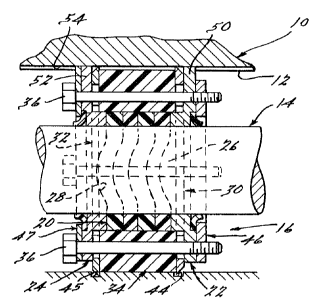
Figure 1 is an exploded cross section through
a seal assembly of the instant invention;
Figure 2 is an elevational view of a retaining
ring used in the assembly of Fig. 1: and
Figure 3 is a view, similar to Fig. 1, of an
assembled seal.


DETAILED DESCRIPTIO~ OF THE PREFER~ED
EMBODIMENT OF THE INVENTION

In accordance with a preferred and constructed
embodiment of the instant invention, a seal housing 10
has an enlarged circular bore 12 therein for the accep-
tance of a shaft 14. The shaft 14 is journaled by a
seal assembly 16 that is mechanically retained ln the
bore 12 of the housing 10, as will be described.
In accordance with the present invention, the
seal assembly 16 comprises one or more deformable
elastomeric seal elements 20 which journal the shaft
14, The seal assembly 16 is initially telescoped over
the shaft 14 without contact therewith for ease and
safety of installation. Subsequently, the seal ele-
ments 20 are radially contracted into contact with the
shaft 14 to effect a seal thereagainst.
More specifically, and in accordance with one
feature of the instant invention, radial contraction of
the seal elements 20 is effected by a pair of backup
rings 22 and 24 which have one or more axially

extending nesting undulations 26 and 28, respectively.
As the backup rings 22 and 24 are drawn toward one


1301208

another by tightening a plurality of machine-screws 36,
the seal elements 20 are de~ormed lnto the shape of the
undulations 26 and 28 in the backup rings 22 and 24.
Thus, the internal diameter of each of the seal ele-

ments 20, which initially is slightly larger th~n theshaft 14, is reduced as it conforms to the nesting
undulations of the rings 22 and 24. As the two backup
rings 22 and 24 move toward one another, sealing con-
tact of the seal rings 20 against the shaft 14 is
achieved.
In accordance with another feature of the
instant invention, the seal assembly 16 is mechanically
positioned in the bore 12 of the housing 10 by a pair
of serpentine retaining rings 30 and 32 that are
disposed between the backup rings 22 and 24 and on
opposite sides of an intermediate bore sealing ring 34.
As the seal assembly 16 is assembled by tightening of
the plurality of bolts 36, serpentine or undulating
portions 38 and 39 on the retaining rings 30 and 32,
respectively, are flattened out causing the outside
diameter thereof to expand radially outwardly, bringing
sharp edges 40 and 42 thereon into engagement with the
bore 12 or, alternatively, as seen in Fig. 3, into a
pair of circumferential positioning grooves 44 and 45.
Suitable washers 46 and 47 and dust seals 48 and 49 are
provided to complete the seal assembly 16.
In accordance with yet another feature of the
instant invention, radial expansion of the bore sealing
ring 34 is achieved by axial compression of the
retaining rings 30 and 32. The sealing ring thus


~301208

exerts a radially inward bias on the seal elements 20
and a radially outward bias against the walls of the
bore 12 in the housing 10.
It is important that the seal assembly 16 be
positively positioned relative to the bore 12 so that
rotation of the shaft 14 relative to the seal element
16 does not effect indexing of the seal assembl~ 16.
Accordingly, backup rings 22 and 24 are provided with
radially extending locking fingers 50 and 52 that are
accepted in a complementary groove 54 in the housing 10
While th~ preferred embodiment of the inven-
tion has been disclosed, it should be appreciated that
the invention is susceptible of modification without
departing from the scope of the following claims.


Representative Drawing
A single figure which represents the drawing illustrating the invention.
Administrative Status

For a clearer understanding of the status of the application/patent presented on this page, the site Disclaimer , as well as the definitions for Patent , Administrative Status , Maintenance Fee  and Payment History  should be consulted.

Administrative Status

Title Date
Forecasted Issue Date 1992-05-19
(22) Filed 1987-03-11
(45) Issued 1992-05-19
Deemed Expired 2008-05-20

Abandonment History

There is no abandonment history.

Payment History

Fee Type Anniversary Year Due Date Amount Paid Paid Date
Application Fee $0.00 1987-03-11
Registration of a document - section 124 $0.00 1987-05-29
Registration of a document - section 124 $0.00 1991-11-19
Maintenance Fee - Patent - Old Act 2 1994-05-19 $100.00 1994-05-03
Maintenance Fee - Patent - Old Act 3 1995-05-19 $100.00 1995-04-04
Registration of a document - section 124 $0.00 1995-08-24
Maintenance Fee - Patent - Old Act 4 1996-05-20 $100.00 1996-04-17
Maintenance Fee - Patent - Old Act 5 1997-05-20 $150.00 1997-04-22
Maintenance Fee - Patent - Old Act 6 1998-05-19 $150.00 1998-04-28
Maintenance Fee - Patent - Old Act 7 1999-05-19 $150.00 1999-04-19
Maintenance Fee - Patent - Old Act 8 2000-05-19 $150.00 2000-05-08
Maintenance Fee - Patent - Old Act 9 2001-05-22 $150.00 2001-05-14
Maintenance Fee - Patent - Old Act 10 2002-05-20 $200.00 2002-05-02
Maintenance Fee - Patent - Old Act 11 2003-05-20 $400.00 2003-05-21
Maintenance Fee - Patent - Old Act 12 2004-05-19 $250.00 2004-05-04
Maintenance Fee - Patent - Old Act 13 2005-05-19 $250.00 2005-05-04
Maintenance Fee - Patent - Old Act 14 2006-05-19 $250.00 2006-05-16
Owners on Record

Note: Records showing the ownership history in alphabetical order.

Current Owners on Record
MACROTECH POLYSEAL, INC.
Past Owners on Record
DUKE, JAY THOMAS
MACROTECH FLUID SEALING, INC.
MICRODOT INC.
ZITTING, GORDON TREE
Past Owners that do not appear in the "Owners on Record" listing will appear in other documentation within the application.
Documents

To view selected files, please enter reCAPTCHA code :


To view images, click a link in the Document Description column. To download the documents, select one or more checkboxes in the first column and then click the "Download Selected in PDF format (Zip Archive)" or the "Download Selected as Single PDF" button.

List of published and non-published patent-specific documents on the CPD .

If you have any difficulty accessing content, you can call the Client Service Centre at 1-866-997-1936 or send them an e-mail at CIPO Client Service Centre.


Document
Description 
Date
(yyyy-mm-dd) 
Number of pages   Size of Image (KB) 
Representative Drawing 2001-07-25 1 16
Drawings 1993-10-30 1 38
Claims 1993-10-30 2 79
Abstract 1993-10-30 1 14
Cover Page 1993-10-30 1 12
Description 1993-10-30 4 119
Fees 1997-04-22 1 74
Fees 1996-04-17 1 54
Fees 1995-04-04 1 53
Fees 1994-05-03 1 49