Note: Descriptions are shown in the official language in which they were submitted.
21PATAP5 LTN~ 2000.2
Patent
TRUSS TRANSPORTATION TRAILER
Field of the Invention
The present invention relates to a trailer for hauling
prefabricated roof trusses, and more particularly, to a trailer
which incorporates power assisted devices and safety devices to
permit a single operator to adapt the trailer to accommodate
various sizes of trusses and to safely operate the trailer when
unloading said trusses.
Background of the Invention
Increased building costs and improvements in the
ability to construct effective roof trusses have resulted in an
increasing use of prefabricated roof trusses in the construction
of both commercial and residential buildings. Roof trusses,
which are assembled at a manufacturing facility, are moved to the
job site most commonly on a tractor-trailer operated on the
highway system. Because of the differing requirements of the
buildings, the dimensions and configurations of the trusses vary
marketedly from building to building. As a result, the trailers
utilized to transport the trusses must be capable of adaptation
in order to handle the various sizes and configurations of
trusses which may be fabricated in a single manufacturing plant.
Conventional tractor-trailer combinations for moving
trusses consist of a standard over-the-road tractor equipped with
a "fifth wheel" coupler by which a trailer may be connected to
the tractor. A first bolster is mounted above the trailer
portion of the "fifth wheel" coupler to support the front end of
the trusses. An independent rear trailer is equipped with a
similar bolster to support the rear end of the trusses. The
independent trailer/bolster assembly is connected to the "fifth
wheel" coupling mechanism through a pipe structure. The 'distance
between the front bolster and the rear bolster may be adjusted by
_ 1 _
21PATAPS LTM 2000.2
Patent
moving the trailer along a cylindrical pipe which serves as the
backbone of the truck. In cases where the trusses have a high
pitch or are very long, a vertical extension may be added to the
front and rear bolsters to increase the height thereof so that
longer or deeper trusses may be carried on the tractor-trailer
without the apex of the truss dragging on the ground.
Adapting the trailers fox various sizes of trusses is
quite labor intensive. Adjusting the distance between the front
and rear bolsters usually requires two people; one person to
drive the tractor and one person to signal the driver when
locking holes are lined up in the pipe structure. Several men
are required to carry the vertical extension bolsters and mount
them on the truck when increased height is needed. If the
tractor breaks down, it becomes necessary to unload the trusses
before the tractor can be moved away from the trailer and a new
tractor connected. This process as well requires numerous men to
effect.
Another problem with conventional tractor-trailer
combinations is the inability to adjust the height of the load
after the trusses are mounted. This can create an extreme safety
hazard. In one known instance, a tractor-trailer carrying
trusses attempted to cross a railroad grade crossing. The
clearance was such that the trusses grounded on the center of the
grade and effectively "hung up" the tractor-trailer combination.
Before the tractor-trailer could be moved from the railroad
crossing, it was necessary to get additional equipment to unload
the trusses. Obviously if a train had arrived in the meantime,
the results could have been disastrous.
Accordingly one object of the instant invention is to
provide a trailer which is capable of standing alone in a loaded
- 2 -
21.PATAPS LTM 2000.2
Patent
condition. A further object of the invention is to provide a
trailer which may be adjusted in length by one man. Yet another
object of the instant invention is to provide a trailer which can
be adjusted in height in either the loaded or unloaded condition.
These and other objects and advantages of the present invention
will be in part apparent and in part pointed out hereinafter.
Brief Description of the Drawings
When considering the following detailed description in
conjunction with the drawings, Fig. 1 is a pictorial drawing
showing a conventional tractor-trailer arrangement.
Fig. 2 is a similar drawing of the trailer of the
instant invention in its lengthened state.
Fig. 3 shows the trailer of the instant invention in
the shortened state.
Fig. 4 is a close-up view of the unique length locking
device taken along lines 3-3 of Fig. 1
Fig. 5 is a partial view of the truss trailer showing
the rear trailer assembly and the truss carrying bolster from the
side.
Fig. 6 is a view of Fig. 5 from the tractor looking
towards the rear of the assembly.
Detailed Description of the Tnvention
Referring now to the drawings wherein like reference
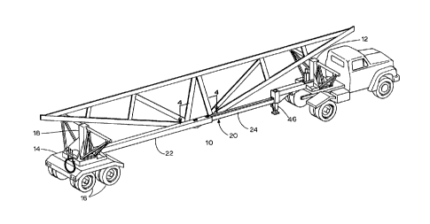
characters represent like elements, Fig. 2 shows a trailer
generally designated as 10 comprised of a front truss supporting
bolster 12, which is fitted with a conventional fifth wheel
attachment mechanism (not shown), and a rear trailer assembly 14
comprised of a conventional wheel and axle mechanism 16 and a
rear bolster 18. Rear trailer assembly 14 is connected to front
truss supporting bolster 12 by an extendable/retractable box beam
- 3 -
21PATAPS LTM 2000.2
Patent
20. Comparing Fig. 2 and Fig. 3, it will be seen that rear
trailer assembly 14 can be moved closer or farther away from
front truss supporting bolster 12 by positioning it along various
locations along extendable/retractable box beam 20.
Fig. 4 illustrates in greater detail a portion of the
components of extendable/retractable box beam 20. As will be
seen, extendable/retractable box beam 20 is composed of an outer
box beam 22 in sliding relationship with an inner box beam 24.
Sleeved holes 26 are provided at intervals along inner box beam
24, the purpose of which will become apparent. Outer box beam 22
is provided with a positive lock mechanism 30 consisting of a
lock retainer 36 and a lock safety 38. Outer box beam 22 is
additionally slotted in the area defined by lock retainer 36 and
lock safety 38 so that free access may be obtained to inner box
beam 24 in this area. The combination inner box beam/outer box
beam assembly is further provided with a means for moving outer
box beam 22 in relationship to inner box beam 24. This means
(not shown) may be of any of the conventional structures known,
such as an hydraulic cylinder, an electric motor, an electric
chain winch, an endless chain mechanism, or any other convention-
al structure suitable far moving one piece laterally in
relationship to a second piece. Positive lock mechanism 30
further consists of a lock body 32 fitted with lock bar 34. The
relationship of the various components will become apparent as
the means of adjusting the length of the trailer is described.
To adjust the length of the trailer, the operator parks
the tractor-trailer combination, sets the brake on the tractor,
and turns off the engine. He then removes a control mechanism
(not shown), which includes means for operating the power means
which adjusts the length of expandable/retractable box beam 20.
He then unlocks the beams. This procedure is the exact opposite
of that hereinafter described for docking the beams and will be
- 4 -
21 PATAP 5 LTI~~I 2 0 00 . 2
Patent
fully understood from reading that description. As inner box
beam 24 moves in relationship to outer box beam 22, one of a
plurality of holes 26 will periodically appear in the slot cut in
outer box beam 22, the perimeter of which is defined by lock
retainer 36 and a lock safety 38. Holes 26 are sleeved and are
sized to slidably engage lock bar 34. When the desired separation
between front bolster 12 and rear bolster 18 has been attained,
the operator adjusts the length so that one of holes 26 appears
in the aforementioned slot. Positive lock 30 is then placed
within lock retainer 36 so that lock bar 34 engages the selected
hole 26. The relationship of outer box beam 22 and inner box
beam 24 is then further adjusted so that the end of positive lock
30, immediately over lock bar 34, passes into the covered recess
created by lock retainer 36. At this point, it will be noted
that the relationship of outer box beam 22 and inner box beam 24
is now fixed. Due to the covered recess in lock retainer 36, it
would be impossible to remove positive lock 30. As an additional
safety feature to prevent decoupling of this relationship,
locking safety pin 40 is passed through hole 42 in lock safety 38
and hole 44 in lock body 32. Locking safety pin 40 can be
retained in position by use of a cotter pin, hair pin, or any of
the numerous devices commonly used to retain a pin in place.
Front bolster 12 is further provided with a front
trailer support 46, which may be extended or retracted by any of
the various conventional means. When front trailer support 46 is
extended so that it makes contact with the ground, front bolster
12 may be sufficiently raised to permit the fifth wheel mechanism
to be disengaged, thus allowing the tractor to be moved away from
the trailer. This is particularly advantageous in the event of a
breakdown of the tractor as it permits a substitute tractor to be
attached to the trailer assembly without the need for removing
the load. The ability to utilize front trailer support 46 to
21PATAPS LTM 2000.2
Patent
support the front end of the trailer when in a loaded condition
is a .result of the rigidity furnished by the mated inner and
outer box beams. Where a cylindrical structure is utilized, as
on conventional trailers, sufficient lateral stability is not
provided and any attempt to support the front bolster results in
a twisting whereupon the trusses on one side or the other of the
trailer are permitted to slide onto the ground.
Considering now Figs. 5 and 6, the unique construction
of the bolster assembly will be described. The front and rear
bolsters are identical; the front bolster being mounted above the
fifth wheel connection mechanism and the rear bolster being
mounted upon rear trailer assembly 14. The bolsters consist of a
bolster base 47, which is mounted directly upon rear trailer
assembly 14 or the fifth wheel connection device and is strongly
braced so as to rigidly support inner bolster riser 48 which is
perpendicular to bolster base 47. Outer bolster riser 50 surrounds
inner bolster riser 48 in slidable engagement. Outer bolster 50
and inner bolster riser 48 are so sized and constructed as to
permit outer bolster riser 50 to move freely along inner bolster
riser 48 without any tipping or twisting occurring.
Affixed to outer bolster riser 50 are left and right
truss support mechanisms. These mechanisms are mirror images of
each other. Each mechanism is comprised of truss support 52,
which may be optionally equipped with an extension 54 to increase
the number of trusses which may be carried. Truss support 52 is
attached to outer bolster riser 50 by inner truss support riser
56 and outer truss support riser 58. These truss support risers
are fastened to outer bolster riser 50 via outer bolster riser
pivot plate 59, which is rigidly affixed to outer bolster riser
50. Inner truss support riser 56 is affixed to outer bolster
riser pivot plate 59 at inner truss support riser lower pivot
point 60 and to truss support 52 at inner truss support riser
- 6 -
21PATAPS LTM 2000.2
Patent
upper pivot point 62. Likewise, the outer truss support riser is
affixed to the bolster riser pivot plate at outer truss support
riser lower pivot point 64 and to truss support 52 at outer truss
support riser upper pivot point 66. Tt will be noted in Fig. 6
that when truss support 52 is in its carrying position, inner
truss support riser 56 is essentially perpendicular to truss
support 52 and parallel to outer bolster riser 50. It will be
further noted that outer truss support riser upper pivot point 66
is near the outer end of truss support 52, whereas outer truss
support riser lower pivot point 64 is substantially closer to
inner truss support riser lower pivot point 60. This results in
outer truss support riser 58 being appreciably longer than inner
truss support riser 56 and creates a diagonal brace to support
the outer end of truss support 52.
The positioning of the left and right truss support
assemblies is controlled by a truss support control cylinder 68
and left and right locking mechanisms 70. Truss support cylinder
68 is a double acting hydraulic cylinder which is activated by a
control 72 which selectively lowers or raises either the left-hand
truss support 52 or the right-hand truss support 52. Each locking
mechanism 70 is rigidly attached to outer bolster riser 50 and
comprises a spring loaded plunger (not shown) which engages inner
truss support riser 56 so as to lock it in a vertical position
and lock truss support 52 in an horizontal load supporting
position. Locking mechanism 70 further comprises a solenoid
device which can be activated to withdraw the plunger and thus
release inner truss support device 56 from its locked vertical
position. When it is desired to unload the trusses carried upon
truss support 52, a switch is activated adjacent to control
handle 72. This switch will energize both solenoids on either
the left-hand side or the right-hand side of the vehicle thus
releasing both the front and rear truss support mechanisms
_ 7 _
21PATAPS LTM 2000.2
Patent
1~~~~~9
on either the left side or right side of the truss support
trailer. Control handle 72 is then moved in a direction that
activates truss support cylinder 68. Truss support cylinder 68
will elongate and slowly cause inner truss support riser 56 and
outer truss support riser 58 to pivot about their respective
lower pivot points and thus move truss support 52. As a result
of the spacing of the inner and outer truss support lower pivot
points 60 and 64, respectively, and the difference in length of
inner truss support riser 56 and outer truss support riser 58, a
unique unloading action occurs in that truss support 52 will move
laterally away from the vehicle before the outer end begins to
lower towards the ground. This has the effect of moving the
trusses outward from the vehicle so that when they slide from
truss support 52 and fall onto the ground, their inner most end
will be outside of the tread width of the trailer and thus permit
the trailer to be driven away without the necessity of moving the
trusses. Following the unloading of the trusses, control handle
72 is then moved in the opposite direction. Hydraulic cylinder
68 retracts and returns truss support 52 to its raised horizontal
position and locking mechanism 70 automatically activates and
locks the support in this position. Because of the use of the
double acting power cylinder, it is possible to raise truss
support 52 to its horizontal position even when a load is on the
truss support. Thus it is possible to unload only part of the
trusses carried on the truss support. This is accomplished by
firmly chaining the inner trusses to truss support 52 and inner
truss support riser 56. When the cylinder is activated, truss
support 52 tilts until the unrestrained outer trusses slide to
the ground. When hydraulic cylinder 84 is further retracted, the
inner trusses, which have been chained to truss support 52, and
inner truss support riser 56 are returned to the carrying posi-
tion along with truss support 52.
g
21PATAPS LTM 2000.2
13~~~~~ Patent
Additional control devices, which are not shown, can
also be provided in the vicinity of control handle 72 which will
permit selective raising and lowering of the outer bolster riser
with respect to the inner bolster riser at either the front end
or rear of the trailer. This is most conveniently accomplished
with an hydraulic cylinder mounted upon inner bolster riser 48.
The cylinder or other lifting device will have sufficient power
to raise and lower the outer bolster riser even when a full load
of trusses is carried on truss support 52.
It is thus seen that it is possible to carry the
trusses with a minimum amount of ground clearance when the
trailer is operating on a smooth surface and it is possible to to
increase the ground clearance by raising the outer bolster risers
when carrying the trusses over rough ground or over humps in the
road, such as might be encountered at a railroad grade crossing,
where the trusses may drag on the ground and hang up the trailer.
On occasion the building which is being constructed
will require trusses which are angled only on one side. These
are commonly called mono trusses. To handle the mono trusses,
rear trailer assembly 14 is equipped with steps to support the
apex of the mono truss. This step mechanism consists of an inner
mono step support 74 and an outer mono step support 76, which are
rigidly affixed to rear trailer assembly 14. The support mecha-
nism itself consists of a mono step 78 to which are pivotally
affixed an inner leg 80 and an outer leg 82. The inner and outer
legs are sized to slidably fit within inner mono step 20 support
74 and outer mono step support 76. When the mono step is mounted
on the trailer, inner leg 80 is firmly supported within inner
mono step support 74. Outer leg 82 is releasably supported
within outer mono step support 76. For over-the-road hauling,
the trusses are loaded with the apex resting upon the mono step.
At the building site, mono step control cable 84 is connected to
- 9 -
21PATAP5 LTM 2000.2
Patent
~3~~~~~
the point where truss support control cylinder 68 is attached to
inner truss support riser 56. Mono step control cable 84 is
flexible and of sufficient strength to hold the outer end of mono
step 78 in its raised position. Once mono step cable 84 is
attached, the lock on outer leg 82 may be released. The controls
are then activated in the same fashion as would be done for
unloading a load of full trusses. As rear truss support 52 is
lowered to the unloading position, mono step control cable 84
will in turn lower mono step 78 to an unloading position, thereby
allowing the mono trusses to slide to the ground in the same
fashion as full trusses.
It is thus seen that the unique truss transportation
trailer of the instant invention provides a truss support trailer
which may be easily and safely controlled by a single operator
and which can be utilized to transport a large variety of truss
sizes and configurations safely from the point of manufacture to
the point of use. Although the present invention has been
described with reference to a particular detailed embodiment
thereof, it should be understood that the description is intended
to be illustrative and not in a limiting sense. Many other
variations may be devised by those skilled in the art which will
fall within the true spirit arid scope of the principles of this
invention.
- 10 -