Note: Descriptions are shown in the official language in which they were submitted.
~3~14~9
2 26541-57
The present invention relates to an apparatus for detecting a
gaseous component in air, having a sample chamber that contains a
sensor, an air sample passing through said sample chamber through
an inlet and an outlet, both of which can be closed.
In a detection apparatus that is described in United States
Patent No. 4,384 925 issued May 24, 1983, to Joseph R Stettes et
al, a sensor housing with a sensor is arranged in a flow line for
an air sample that is to be checked. From time to time, the flow
line is interrupted ahead of and after the sensor, so that a de-
fined quantity of the air sample is enclosed within this section
of the line and the sensor housing. The sensor operates on the
coulometric principle, so that the measured charged particles con-
stitute a measure of the gas concentration that is contained in
the air-sample chamber for a period of time that is governed by a
control unit. This value is then used as a calibrating value for
subsequent continuous measurement by an independent, second sen-
sor.
In this known apparatus, however, the calibrating sensor is
constantly exposed to the air sample prior to the actual calibra-
tion process, so that at the start of the calibration process,
which is to say, when the sensor housing is closed off, there is
a non-replicable, frequently varying concentration of gas therein.
This unstable measurement condition can delay very greatly the
measurement time needed until a stable state is achieved. In ad-
dition to this, the separated sections of the flow line can also
be regarded as a part of the measurement chamber, within which
pockets of the air sample of other concentrations than in the sen-
sor chamber can remain, and this can contribute to degradation of
~,
13~J~479
3 26541-57
the results of the measurement process.
A further detection apparatus is known from United States
Patent No 3,854,320. This has a sample chamber into which the gas
that is to be checked--in this case the exhaled breath of a donor-
-is conducted through an inlet and, after this has been flushed
through, is exhausted to the atmosphere through an open outlet.
Within the sample chamber there is a sensor, this being covered
with a capsule during the flushing phase, said sensor being used
to detect a component gas contained in the air sample which, in
the case in question is alcohol contained in the donor's breath.
When, after a sufficiently long period of flushing time, a
significant air sample is contained within the sample chamber, the
cap is lifted off the sensor, so that this is now freely exposed
to the air sample that is to be checked. During this exposure
time the sensor sends a signal to a gating or evaluation unit that
then indicates the concentration of the gas components to be de-
tected that are present in the sample chamber. During the measure-
ment time the inlet is closed, so that no additional air sample
can enter. If the measurement process is to be terminated, the
cap is once again positioned over the senosr so that this is then
once again isolated from the sample chamber. At the same time,
the sensor and the area that is enclosed by the cap are flushed
with ambient air, in order to ensure that all ~esidual quantities
of still-present sample gas are removed from the sensor chamber.
In the known detection apparatuses the sample chamber is only
cut off from the inlet with regard to flow, although a constant
and not inconsiderable exchange of gas takes place with the sur-
rounding atmosphere through the open outlet, so that the initial
13t~1479
4 26541-57
concentration of the gas that is to be detected decreases constant-
ly during the measurement phase, as a result of external influenc-
es.
For this reason, it is desirable to so improve a detection
apparatus of this kind that the sensor enters a stable initial
state that is unaffected by the flow of gas that is to be checked,
and does so prior to the start of the measurement phase; and that
the sample chamber has the smallest possible volume and offers
the lowest possible resistance to the flow of the air sample, so
as to achieve a short measurement phase.
The improvement of the detection apparatus lies in the fact
that the sample chamber is divided into a measurement chamber that
contains the sensor, and a flushing chamber, both chambers being
connectable through a closable measurement chamber port; and in
the fact that the inlet and the outlet open out into the flush-
ing chamber; and in that in order to establish the sample quan-
tity diffusing into the measurement chamber at the start of a
specifiable time period both the inlet and the outlet are closed
off and at the same time the measurement chamber opening is opened;
and in that after the expiry of the time period the measurement
chamber opening is closed.
Because of the present invention it is possible that prior to
the start of the measurement phase, stable initial values can be
assigned to the sensor, because it is covered off from the air
sample that flows through the flushing chamber prior to collection
of the sample.
A covered sensor that operates during its own consumption of
the gas components that are to be detected would thus--even auto-
13~79
26541-57
matically--be reset to its zero point as an initial value.
In addition, a covered sensor does not falsify the subsequent
results of measurement by premature use of the gas components that
are to be detected, as the sample is being taken.
A definable quantity of test air from the flushing chamber is
fed to the sensor in its measurement chamber, this quantity being
determined on the basis of the size of the measurement chamber.
In this connection, a small measurement chamber volume results in
a correspondingly short measurement phase. Accordingly, it is
possible to retain a sufficientlv small resistance to flow of the
flushing chamber volume so that, for example, a sample can be col-
lected by a subject exhaling into the flushing chamber. The quan-
tity of sample air so collected can be subjected to quantitative
analysis from the flushing chamber, without any disruptive outside
influences. In particular, if electrochemical sensors are used,
very precise coulometric measurement can be used. Any degradation
of the measurement process by possible dilution of the air sample
within the measurement chamber is precluded.
If the measurement chamber opening is configured as a dif-
fusion section, the concentration of the gas components to be de-
tected that is present in the measurement chamber can be affected
by the length of time for which the diffusion section remains op-
en if this is less than the time for the adjustment of a state of
equilibrium between the concentrations within the flushing chamber
and in the measurement chamber.
In order to carry out a measurement at very high concentra-
tions that could saturate the sensor, the concentration can be
considerably reduced in this manner, by invoking experimentally
13~7~
6 26541-57
determinable correction factors, so that analytical quantitative
measurement remains possible.
For the case of coulometric measurement, only a small partial
quantity of the air sample present in the flushing chamber and av-
ailable for such a purpose is used for measurement purposes, and
this is used up in a considerably shorter time than would be the
case for the total quantity.
An especially expedient embodiment of the detection apparatus
is seen in the fact that after the expiration of the time period,
both the inlet and the outlet are opened. This entails the par-
ticular advantage that during the measurement process, the flushing
chamber can either be flushed with fresh air, or a new sample col-
lection can be initiated.
It is expedient to form the flushing chamber from a housing
into which both the inlet and the outlet and the diffusion section
open out, with both the first openings being closable by an inlet
seal and an outlet seal on a common seal carrier that is accomo-
dated by a push rod that projects into the flushing chamber and is
axially displaceable by an adjusting element, and which has a dif-
fusion section lock that is so arranged that the diffusion sectionis closed when the inlet and the outlet are open, and open when the
inlet and the outlet are closed. Thus, in a very s;mple manner,
with one stroke of the valve, the flushing chamber can be closed off
from the air sample flowing through it and at the same time the
diffusion section to the measurement chamber is opened. When the
diffusion section is closed once again, the inlet and the outlet to
the flushing chamber will be opened once more.
An embodiment of the present invention will be descr~bed in
' '
~ .
.
13(~14~9
7 26541-57
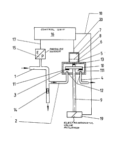
greater detail below on the basis of an embodiment shown in the sin-
ale drawing appended hereto. In this drawing, an air sample line
(l) through which the air sample that is to be checked is supplied,
in the direction indicated by the arrow, is initially connected in
the main flow to the atmosphere through a choke (14). From the air
sample line (l) a narrow inlet (2) branches off into a flushing
chamber (3), this chamber being connected to the atmosphere through
an outlet (4). In addition, this flushing chamber (3) has a dif-
fusion section (5) that forms the connection to a measurement cham-
ber (6) for a detector sensor (7). The sensor (7) is separated off
from the measurement chamber (6) by a partition (8) which, in the
case of an electrochemical sensor, forms a diffusion membrane. A
valve stem (9) projects into the flushing chamber (3~, and this has
a seal carrier (l0) on its end. This is mounted on the end face of
the push rod (9) and has at both its ends flexible rubber pressure
pads (ll, lll) that face the openings (12) of the inlet (2~ and of
the outlet (4). On the extension of the push rod (9~ the seal car-
rier (l0) has a closing element (13) that closes off the diffus~on
section (5).
In order to check an air sample, first--as is shown in the
figure--the air sample is passed through the air sample line (l~,
from which the greater part passes to the atmosphere. A pressure
builds up in the line (l) because of the choke (14), and this LS
signalled by a pressure sensor (15) to a control unit (16~ through
a pressure measurement line (17). A partial flow of the air sample
is passed through the open inlet (2) into the flushing chamber (3),
divided within same, and exhausted to the atmosphere through the
outlet (4). To the point that a specific pressure was present at
:
i301~9
- 8 - 26541-57
the pressure sensor (15) for a time that can be set by the control
unit (16), the valve stem or push rod (9) is moved by an electro-
magnetic valve actuator (19) that is controlled from the control
unit (16) through a valve control line (18) into a position in
which the openings (12) of the inlet (2) and the outlet (4) are
closed simultaneously by the pressure pads (11, 111). At the same
time, the diffusion section (5) is opened because of the closing
element (13) that is lifted off it, and the air sample contained
in the flushing chamber (3) can diffuse through the diffusion
section (5) into the measurement chamber (6). The detector sensor
(7) is activated for measurement by the control unit (16) through
the sensor line (20). After the expiration of a time period set
by the control unit (16) the valve actuator (19) is activated and
the valve push rod is returned to the position shown in the draw-
ing. Thuæ, a quantity of air to be sampled, which can be deter-
mined by the period of time the diffusion section (5) remains
open, is drawn into the measurement chamber (6) and this sample is
now available for evaluation, unaffected by any influences in the
sample collection system. If a coulometric measurement is made
the gas that is to be detected is consumed by the detector sensor
(7) so that the measured flow that passes through the electro-
mechanical sensor (7) can be evaluated by the control unit (16)
and indicated as a concentration readout.
, X `
,: .
,