Note: Descriptions are shown in the official language in which they were submitted.
13(~ 37
BACKGROUND OF THE INVENTION
1. Field of Invention
The present invention relates to self-locking fasteners
and, in particular, to bolts, nuts, washers and the like having
serrated bearing surfaces that provide resistance against the
13~ 7
fastener becoming loosened unintentionally after it has been
seated. The self-locking fastener of the present invention can
be used to particular advantage for workpieces having
relatively soft bearing surfaces whereby marring of the
workpiece surface is minimized.
2. Descri~tion of the Prior Art
A serious problem in joints secured together by
threaded members is the possibility of joint separation due to a
nut backing-off from a bolt or a bolt backing-out from a nut or
other internally threaded member. Generally, this result can
occur when the joint is subjected to vibrations.
Various proposals have been suggested in the past to
either eliminate or greatly reduce the unintentional loosening of
threaded members. ~ecause of the wide variety of applications in
which this undesirable result can occur, many different types of
locking devices have been developed. One approach has been to
treat the bearing surface of the fastener in such a manner that
the resistance to relative rotation between the fastener and a
workpiece in which the fastener is installed is greater than the
resistance to relative movement between the mating threads. As a
result, the resistance to rotation between the mating threaded
13~14~7
parts no longer is the critical factor in determining whether the
threaded parts will turn relative to each other.
One important requirement of these fasteners is that
the "off" torque (torque required to loosen a tightened fastener)
be greater than the "on" torque (torque required to seat a
fastener properly.~
Because the bearing surface of these fasteners, for the
most part, are serrated or are provided with teeth
or the like which are arranged to dig into the workpiece to
create resistance to relative rotation between the fastener and
the workpiece, some damage or marring of the workpiece bearing
surface will occur as these fasteners are seated and removed.
Such damage to the workpiece causes it to weaken. Hence, a
second important requirement of these fasteners is that the
effect of marring or damage to the workpiece is minimized.
Generally, most prior art fasteners provided with a
locking characteristic in the bearing surface fail to satisfy
concurrently these and other requirements. Those fasteners
available at the present time having improved "off" torque to
"on" torque ratios dig into the workpiece in such a manner or to
such an extent as to weaken greatly the workpiece. "Notch"
13~ 7
effect (the build up of stress concentrations) is a common result
and may cause fatigue failure of the clamped parts. This problem
becomes more acute as the thickness of the workpiece is reduced.
Those fasteners available at the present time having reduced
adverse effect on the workpiece provide insufficient "off"
torque.
The drawbacks of this type of prior art fastener are
overcome in a fastener such as that disclosed in commonly
assigned U.S. Patent 3,605,845. This patent discloses a
self-locking fastener which provides a resistance to unintended
rotation between the fastener and the worXpiece and yet causes a
minimum amount of marring of the workpiece surface with which the
fastener bearing surface is in contact. This is accomplished by
providing a smooth surface annular ring about a plurality of
radially disposed serrations which, upon engagement with the
workpiece, opposes further penetration of the serrations and
controls the extent of penetration of the serrations.
A similar improved fastener is also disclosed in
commonly assigned U.S. Patent 3,825,051. This patent discloses a
self-locking fastener having a polygon shaped workpiece bearing
surface, such as a hex-head, where the serrated segment is formed
within an annular segment so that circumferentially discontinuous
13~1497
smooth-faced outer bearing surfaces are formed across adjacent
flats of the polygon configuration.
- Thus, it is an object of the present invention to
provide a new and improved self-locking fastener having a locking
mechanism included in the bearing surface of the fastener and
which is also provided with a stress regulating configuration
within the locking mechanism to control the extent of penetration
of the fastener into the workpiece.
It is another object of the present invention to
l~ provide a self-locking fastener of this type which provides
improved resistance to unintended rotation between the fastener
and a workpiece and yet causes a minimum amount of marring of the
workpiece surface with which it is in contact.
It is a further object of the present invention to
provide a self-locking fastener which iæ relatively simple in
construction and inexpensive to fabricate.
SUMMARY OF THE INVENTION
The self-locking fastener of the present invention has
13(~1~97
a bearing surface with a plurality of serrations. The
serrations, when viewed along a cylinder concentric with the
longitudinal axis of the fastener, have the appearance of teeth.
Between two teeth are a plurality of intermediate surfaces.
The level of the intermediate surfaces, relative to the teeth,
is between the crest and root of the teeth. In one preferred
embodiment each serration comprises an inclined plane starting
at the crest of a tooth and proceeding downwardly in the
direction of tightening to an intermediate level forming the
intermediate surface and then a second inclined plane extending
downwardly in the direction of tightening from the intermediate
surface to the root of the tooth.
The intermediate surface reduces the marring of the
workpiece by the teeth, yet sufficient resistance to vibration
exists to prevent unintentional loosening of the fastener. The
intermediate surface is approximately parallel to the bearing
surface, but is preferably misaligned relative thereto by up to
ten degrees (10) to permit greater penetration of the workpiece.
BRIEF DESCRIPTION OF THE DRAWINGS
Figure 1 provides a perspective view of a self-locking
bolt constructed in accordance with the present invention.
~,
13~14g~
Figure 2 provides an enlarged portion of the
perspective view of the self-locking bolt shown in Figure 1.
Figure 3 provides an enlarged portion of a cross
sectional view of one embodiment of the plurality of serrations
between two teeth of the self-locking bolt of Figures 1 and 2.
Figure 4 provides an enlarged portion of a cross
sectional view of another embodiment of the plurality of
serrations between two teeth. Both Figures 3 and 4 show an
intermediate surface which minimizes any marring damage.
Figure 5 provides a perspective view of a self-locking
nut constructed in accordance with the present invention.
Figure 6 provides a perspective view of a self-locking
washer constructed in accordance with the present invention.
DESCRIPTION OF THE PREFERRED EM3ODIMENT
1~ The aforementioned objects and other objects of the
present invention will be more fully understood after
- 13~ 7
consideration of the following description taken in connection
with the accompanying drawings.
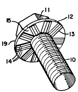
Referring to Figure 1, a self-locking bolt constructed
in accordance with the present invention includes a threaded
shank 10, and a bolt head 11 at one end of shank 10. Bolt head
11 has a bearing flange 12. The bearing surface of flange 12,
that is the surface to be placed in bearing contact against a
workpiece (not shown), is provided with a plurality of outwardly
. disposed serrations 13. In this embodiment the serrations form
sets of preferably two, for example serrations 14, which are
parallel to each other leaving a wedge-shaped portion, for
example 15, between the sets. Serration sets are defined as the
surfaces represented in Figure 1 by four parallel lines.
In another embodiment (not shown) the bearing surface
of flange 12 may include a plurality of radially disposed
serrations rather than the parallel serration sets 14.
Referring to Figure 2, which is an enlarqed portion of
the perspective view of the self-locking bolt shown in Figure 1,
the bolt head 11 is formed at one end of threaded shank 10 and
includes bearing flange 12 and the direction of tightening is
lndicated by the arrow A. The bearing surface of flange 12 has,
.~, .
13(~14~7
in this embodiment, outwardly disposed serrations. When viewed
along a cylinder concentric with the longitudinal axis of the
fastener, the crest of a tooth is represented by 16. A
downwardly inclined surface 17 starts at crest 16 and ends at
one end of an intermediate surface 18. Surface 18 can be
considered approximately parallel to the bearing surface of
flange 12 or the non-bearing top surface 19 of flange 12. A
second downwardly inclined surface 20 starts at the other end
of parallel surface 18 and extends downwardly in the direction
of tightening to a root 21 of the next tooth. Root 21 of the
next tooth is connected by a wall 22, which is generally
parallel to the longitudinal axis of the bolt, to the crest 24
of that tooth. Because the serrations in this embodiment are
parallel to each other, a pie-shaped wedge 23 separates
successive parallel sets. Three pie-shaped wedges 23 are shown
to illustrate this feature of the first embodiment. Each
pie-shaped wedge 23 is at the same plane as root 21. Although
wall 22 can generally be considered to be 90 to the plane of
the bearing surface, variations from 90 are acceptable.
Figure 3 is an enlarged cross sectional view of one set
of serrations shown in Figure 2. From the crest 16 of the tooth,
downwardly inclined surface 17 proceeds in the direction of
tightening to one end of intermediate surface 18. As previously
'- 10
- .
: . .
1 3~ 7
described, the surface 18 is approximately parallel to bearing
flange 12. ~owever, for certain applications, it has been found
to be desirable to form an angle of up to ten degrees (10)
between the surface 18 and the bearing flange to permit greater
penetration of the joint surface. The surface 18 is at a
shallower depth, compared to crests 16 or 24, than the greater
depth of root 21. From the other end of intermediate surface 18,
an inclined surface 20 extends downwardly in the tightening
direction root 21 of the adjacent tooth. The wall 22 extends
from the root 21 to the crest 24 of the adjacent tooth. The
surfaces 17, 18, 20, 21 and 22 along with the crest 16 can be
considered as one set of serrations. When viewed at a right
angle to the surface 18, the set consists of four parallel lines.
Figure 3 also shows another feature of the present
embodiment of the invention. The root 21 is connected to the
wall 22 by a radius or fillet 25, which is not considered
essential to the present invention. The crests 16 and 24 are
also preferably radiused rather than having sharp edges.
Figure 4 is an enlarged cross sectional view of one set
of serrations of another embodiment of the invention. The
embodiment of Figure 4 differs from the one shown in Figure 3 in
that the crests 26 and 27 of the teeth are truncated with small
11
~ . .
": ~
,~
13~1~97
flats. A downwardly inclined surface 28 starts at a truncated
crest 26 and extends in the direction of tightening to one end of
an intermediate surface 29 that is approximately parallel to the
bearing surface of flange 12 but forms an angle therefrom of up
to ten degrees (10). The intermediate surface 29 is at a
level between that of crest 26 and a root 31. Another
downwardly inclined surface 32 begins at the other end of
surface 29 and extends in the direction of tightening to root
31. Surfaces 26, 28, 29, 31, 32 and 33 can be considered as
one set of serrations in this embodiment. Also shown in Figure
4 is a fillet 34 which connects a root 31 with a wall 33 that
is generaIly perpendicular to the surface of flange 12. Fillet
34, however, is not considered essential to this embodiment of
the invention.
Figure S shows the invention described above in the
form of a nut 40.
Figure 6 shows the invention described above in the
form of a washer 50.
In general, the present invention provides means for
limiting the fastener's serrations from penetrating too deeply
into the mating surface of the workpiece (not shown) while still
13~J~ 97
providing "off" torques which are greater than "on" torques.
This control is provided by the intermediate shallower parallel
surfaces (for example 18 in Figure 3, and 29 in Figure 4). As
the fastener is seated, the crests 16, 26 of the serrations
engage the mating surface of the workpiece (not shown) and begin
to penetrate the workpiece. Penetration continues until
intermediate surfaces 18, 29 contact the mating surface of the
workpiece. At this point the total bearing area in contact at
the mating surface will be sufficient to resist further
lO penetration.
The surfaces 18, 29 can be considered intermediate
surfaces which are closer in the axial direction of the fastener
to the non-bearing surface 19 of the bolt than are the crests of
the teeth and which are further in the axial direction of the
15 fastener from the non-bearing surface of the bolt than are the
roots of the teeth. As a result of the relative location of the
intermediate surfaces, the teeth are adapted to penetrate into a
mating workpiece surface in which the bolt is being installed,
and the intermediate surfaces are adapted to control and limit
20 the extent of penetration of the teeth into the workpiece surface
when the fastener is operationally installed with the roots of
the teeth not bearing against the workpiece surface.
13 ~ 7
In particular the fasteners of the present invention
are more suitable for use on workpieces consisting of soft
material such as cast-aluminum or non-heat-treated carbon steel.
While the serrations have been disclosed and described
as originating from the same point on the longitudinal axis of
the fastener, or as being parallel to each other in sets with
each set being separated by a pie-shaped wedge, it is to be
expressly understood that different orientations for the
disclosed serrations of present invention may also be employed
with equally beneficial results.
What is claimed is: