Note: Descriptions are shown in the official language in which they were submitted.
~3(J~
--1--
ABSORBENT PAD
This invention relates to an absorbent pad
especially for use in absorbing body fluids. The
absorbent pad is capable of being used in an at least
substantially upright position, and so is especially
suitable as a breast pad for use by nursing mothers.
It can also be used for absorbing other human fluids,
e.g. as a diaper, incontinence pad, sanitary napkin,
wound dressing, or the like.
BACKGROUND TO THE INVENTION
In the field of breast pads, we are aware of a
specific type of absorbent pad for use by nursing
mothers. This type comprises a substantially
circular pad having radial embossed lines in the form
of spokes extending part way to the circumference.
The radial embossed lines promote wicking of fluid
from the centre of the pad, (which would be against
the`nipple of a mothers breast~, outwardly along the
embossed lines of the pad. In use, these pads have
~3~
--2--
not been found to be ideal because the force of
gravity favours wicking downwards under gravity so
that a pool of liquid is formed at the bottom edge of
the pad, often resulting in leakage onto the mother's
clothing.
Absorbent ~isposable pads for absorbiny
other body fluids are also well known. A very large
number of inventions have been made and patents
granted for disposable diapers, incontinence pads,
sanitary napkins, wound dressings, and the like. In
these itemsl there is typically an absorbent layer
which usually forms the centre of a sandwich
construction having a 1exible fluid-pervious
covering sheet along at least one side. Sometimes
there is a liquid-impervious flexible layer along one
side of the absorbent layer.
Such pads are intended to be worn for a
period of time during which they absorb the body
fluid. Various proposals have been made for enabling
Z the body fluid to be distributed `over the pads,
thereby to give them a longer period of use, make
them less uncomfortable etc. Such proposals include
providing areas of different absorptive power in the
pad by embossing, densifylng etc.
Although many proposals have been made,
there is a need for an absorbent pad that can cause
body fluid to travel from the point it is expelled
from the human body onto the pad and then be
distributed rapidly over a wide area of the pad,
preferably without leaking from the periphery of the
pad.
~3~
--3
SUMMARY OF T~ VENTION
Accordingly the present invention provides
an absorbent pad comprising a fluid-absorbent fibrous
layer having a central portion and a peripheral
portion, and a flexible fluid-pervlous covering sheet
for covering at least one side of the fibrous layer,
a first wicking means in the fibrous layer adapted to
conduct fluid outwardly from the central portion
; towards the periphery of the fibrous layer and a
second wicking means in fluid conductivity in the
fibrous layer with the first wicking means and
adapted to conduct fluid from the first wicking means
in a direction away from the first wicking means.
The pad can be used as a pad for
absorption of human body fluids, e.g. for nursing
mothers, as a wound dressing, an incontinence pad, as
a diaper, as a sanitary napkin, or the like. The
fibrous absorbent layer has at least the two wicking
means. The first wlcking means conducts fluid
outwardly from the centre of the layer towards, but
short of, the edge of the pad. This first wieking
means may extend outwardly along a plurality of
lines. The second wieking means, and any further
wicking means present, are in body liquid
conductivity with the first wicking means for
condueting body fluid in a direetion away from the
first wicking means e.g. in a path around but spaced
from the edges of the absorbent layer.
Preferably the pad is a sandwieh strueture
comprising a body liquid-impervious flexible backing
sheet, the absorbent fibrous layer and the
flui=-pervious covering or facing sheet. The baeking
~3~ 6~
sheet al~d the fluid pervious layer may be attached
together around their peripheries, which conveniently
can extend beyond the edges of the fibrous layer.
The liquid-impervious backing sheet is
preferably substantially impervious to body exudates
but is vapour-permeable. Examples of materials from
which such sheets can be made are coated tissues and
fabrics, perforated or microperforated films, foams,
and melt blown fabrics of micro fibres. Such backing
sheets reduce the occlusive nature of the padsf
particularly when used as nursing pads, thereby
reducing the risk of excessive skin hydration during
use.
The inv~ntion particularly provides an
absorbent article for a nursing mother, said
absorbent article comprising a breast pad of a shape
to be worn over a mothers breast, said pad cornprising
a sandwich structure of a liquid-impervious
vapour-permeable backing sheet, a fibrous absorbent
layer and a fluid-pervious flexible facing sheet, the
fibrous absorbent layer being formed with a plurality
of first wicking means extending outwardly from the
centre of the layer towards the periphery for
conducting body fluid outwardly along a plurality of
lines, and a second wicking means in fluid
conductivity with the first wicking means for
conducting body fluid in a direction away from the
first wicking means.
The second wicking means may be formed by
embossing, by forming a densified edge, or the like.
.
~3~Z~
--5--
~ sandwich structure of a flexible
fluid-pervious sheet, an absorbent fibrous layer and
a liquid-impervious vapour permeable backing sheet
may be used for other types of absorbent pads
referred to above. They can be made to a suitable
shape for the intended use. Conveniently, a
plurality of first wicking means extend outwardly
from the central portion towards the periphery
thereof. The backing sheet and the fluid-pervious
sheet may be attached together, e.g. by plastics
welding or adhesive material, around their
peripheries when the peripheries extend beyond the
periphery of the fibrous layer, or at any other
convenient positions which ensure that the absorbent
fibrous layer is held in position. The absorbent
fibrous layer may be attached to either or both outer
sheets in a similar fashion.
Various embodiments of the invention are
possible. For example, the fibrous layer may have a
; 20 plurality of first wicking means extending radially
outwardly from the central portion towards the
periphery thereof. Alternatively, the~fibrous layer
may have a first wicking means extending outwardly
along a flattened helical path from the central
portion towards the periphery thereof. The term
flattened helical path" means a path which starts
from the central portion and continues as a
continuous path with both curved and straight
portions over a large distance towards the periphery
without crossing itself, so that the appearance is as
if a helix had been flattened in places to form the
straight portions.
~3~
--6--
Preferabl~ the second wicking means follows
a path around the periphery of the absorbent layer
but at a position between the central portion and the
periphery. The first and second wicking means will
hence form a continuous path.
~ If desired, the fibrous layer can have at
`~ least one further wicking means between the second
wicking means and the periphery of the layer, said at
least one further wicking means being in fluid
conductivity with the second wicking means and
adapted to conduct fluid in a direction away from the
second wicking means. ~t least two further wicking
means can be provided, the further wicking means then
being in ~lui~ conductivity with each other, and
arranged to conduct the fluid successively from the
second wicking means towards the periphery of the
pad,
~ .
In one embodiment, a third wicking means in
fluid conductivity with the second wicking means and
adapted to conduct fluid outwardly from the second
uid means, may be provided. In this embodiment
the fibrous layer conveniently also has a fourth
wicking means in fluid conductivity with the third
wicking means and adapted to conduct fluid in a
direction away from the third wicking means. The
fourth wicking means may extend in a direction around
the periphery but at a position between the third
~ wicking means and the pexiphery.
,~
3L3~2~6~
--7--
Conveniently, the first wicking means can
comprise one or more embossed lines extending from
the centre of the fibrous absorbent layer towards the
periphery of the pad. The lines may terminate
shortly before the edge of the absorbent layer. For
one embodiment of breast pad there may be about three
lines at angles of from 100 to 130 to each other.
The centre of the absorbent layer may also have an
embossed indentation adapted for conveniently fitting
over the nipple of the nursing mother's breast. This
indentation (when present) is preferably in liquid
conductivity with the first wicking means so that it
constitutes part of the first wicking means. It is to
be understood that, if desired, more than one
absorbent layer may be present.
The second wicking means can be an embossed
line or lines extending around but spaced from the
periphery of the pad. The line or lines may extend
completely around the periphery or may exten~ part
way around a sector (clockwise and/or anti clockwise)
between adjacent radial first wicking lines.
Conveniently there may be a single embossed second
wicking line closely adjacent to the periphery of the
fibrous absorbent layer and extending completely
around the periphery of that layer.
For a nursing pad, the facing side of the
absorbent layer may resemble a spoked wheel. There
may, for example, be three spokes but further numbers
of spokes can exist is desired. The spokes
conveniently may extend to about Smm from the
periphery of the absorbent layer. Consequently, the
circular second wicking means can be at a radius from
~3~ Z!~6~
--8--
the centre to provide approximately a 5mm gap be~ween
it alld the periphery of the absorbent layer.
In a second embodiment of the nursing pad,
the fibrous absorbent layer can again have a central
embossed indentation to receive the nipple of the
nursing mother's breast and can have spokes extending
outwardly therefrom. As mentioned hereinbefore, the
indentation, when present, constitutes part of the
first wicking means. However, in this embodiment, the
exterlor ends of the spokes do not lead to an
embossed circumferential channel but to a densified
edge at the periphery of the absorbent layer. The
spokes may terminate at the start of the densified
edge or may end completely at the circumEerence oE
the absorbent layer. The densified ~or crushed) edge
may have a bulk density of at least about ten times
that of the least dense portion of the absorbent
layer. There may be a gradually increasing density
gradient to the edge of the layer. The nursing pads
conveniently are substantially circular in plan view.
The densified edge may be made by
crush~cutting of the absorbent layer. The densified
edge is such that fluid reaching it is rapidly
transported in a direction extending away from the
radial channels embossed on the absorbent layer. The
- fluid conveniently is transported in a
circumferential direction by the densified edge away
from the radial spokes
-
The absorbent layer itself can be any
suitable pad of an absorbent matèrial. It may be a
single layer or a plurality of layers of suitable
~3C3~
g
thickness. I-t may be made of absorbent cellulose,
such as defibrillated wood fibres, tissue wadding or
the ll~ce, or a combination of suitable materials.
The purpose of the absorbent layer is to absorb khe
fluid which reaches the centre of it.
Defibrillated wood fibres can comprise
coarse or fine fibre pulps typical of softwoods and
hardwoods, respectively, or mixtures thereof~ These
pulps can be produced by any conventional pulping
and/or bleaching process and may additionally be
; -treated with surface active agents to improve
softness, to aid defibrillation or to promote the
formation of permanent densified layers or regions in
the pad. If desired, skin-forming agents, such as
water or polyvinyl acetate may be used ~o treat
absorbent cellulose to promote absorption over as
great an area as possible. They also make the
embossed wicking means more permanent.
The wicking means for conducting the liquid
from the centre and around the edges of the absorbent
layer may be formed by any standard embossing means.
Similarly, where densification is effected, this may
be by any suitable crush cutting, pressing or the
like, of the absorbent layer.
; The flexible liquid-impervious backing
sheet, when present, can be any suitable
- liquid-impermeable backing sheet. Particular examples
are vapour permeable polymeric films. If desired
such a backing sheet may be backed by a further
layer, e.g. a non-woven fabric.
'
.
~3~
--10--
The flexible fluid-pervious facing sheet
can be any suitable such sheet which will permi-t the
body fluid to pass through it. A polypropylene
non-woven fabric is particularly convenient to use
The facing sheet and backing sheet may be joined
together around the edges in any convenient manner,
e.g. by heat-sealing, adhesive or the like.
Additional backing layers may be attached in any
suitable manner. The additional backing layers, when
present, may provide a non-slip surface or act as a
substrate for an adhesive attachment means. The
adhesive attachment means Eor a breast pad may, for
example, involve one or more strips rom which a
cover film may be retnoved to reveal an adhesive
surface for attachment to the interior of the
mother's brassiere. For other uses other attachment
means may be provided, e.g. securing tabs for an
diaper or incontinence pad.
In the case of a breast pad, the embossing
is such that the portion adapted to fit over the
nipple conveniently is central in a circular breast
pad. However, other shapes can be used.
Furthermore, the point ~rom which the wicking lines
extend outwardly need not be at the exact centre.
The wicking lines conveniently extend
outwardly in several directions. ln use, for breast
pads, the pads can be positioned in any radial
position including the position where there is a
vertical wicking line extending from the centre
downwardly. The pads may, however, be marked to show
a top point and have wicking lines extending
outwardly with the nearest passages to the bottom
.
~3~
point being at about 60 to the vertical. Even if a
pad does have a vertical downwardly extending
passage, it has been found that the fluid, after
wicking towards the edge continues wicking around the
second wicking means away from the bottom edge. The
continuence of wicking around the edge of the pad
means that fluid is continually drawn away from the
central area of impingement, towards the edge and
around the edge. This reduces the possibility of
stains to the clothes of the mother by leakage at the
bottom and also enables the breast pad to be used for
a reasonable length of time.
As indicated above, the absorbent pad may
be utilised as a wound dressing, a diaper an
incontinence pad or other suitable pad for absorption
of human fluids. The invention further provides such
products comprising a pad in accordance with the
invention. The shapes of such pads and consequently
the products themselves can be varied to suit the
particular use to which the pads are to be put. Pads
suitable as wound dressings may be made with or
without the liquid-impervious flexible backing sheet,
dependant on whether containment of wound exudate is
desired or transport of exudates to a secondary layer
is desired.
BRIEF DESCRIPTION OF THE DRAWINGS
The invention is illustrated in
non-limiting manner by reference to the accompanying
drawings ln which:
~L3U2~6~L
-12-
Figure 1 is a plan view of a first embodiment of a
nursing mother's absorbent pad in accordance with the
invention;
Figure 2 is a cross section through II-II of figure
1 ;
.
Figure 3 is a plan view of a second embodiment of a
nursing mother's absorbent pad in accordance with the
invention;
Figure 4 is a cross section through IV-IV of figure
3;
Figure 5 and 6 are plan views of third and fourth
embodiments of a nursing mo~her's absorbent pad in
accordance with the invention.
Figure 7 is a plan view of a sanitary pad in
accordance with the invention, and
Figure 8 is a plan view of a diaper/incontinence pad
in accordance with the invention.
DETAILED DESCRIPTION
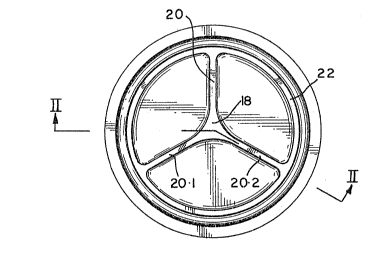
In figures 1 and 2 a breast pad for a
nursing mother has a liquid-impervious
vapour-permeable backing sheet 10 of cellulose tissue
treated with a repellant agent such as AQUAPEL 360XC
~trade name) from Hercules Company, with an absorbent
layer in the form of a pad 12 positioned on it. The
13V ~
13-
pad 12 is sandwiched between the sheet 10 and a
liquid-pervious sheet 1~ of polypropylene non woven
fabric. The sheets 10 and 14 are attached together
~y heat sealing around their periphery 16.
Before or after adhering the sheets 10 and
14 together, embossing is carried out to form the
embossed shape shown in figure 1. Thus there will be
first wicking means comprising a central indentation
18 and three radial indentations 20, 20.1 and 20.2
radially spaced at 120, and a second wicking means
in the form of a circumferential indentation 22,
joining the ends of the radial indentations to form a
three spoked wheel pattern.
In use, the indentations 18, 20 and 22
enable fluid to be led to and around the outer
peripheral portion of the absorbent layer.
~eferring now to figures 3 and 4, the
periphery of the pad is densified by means of crush
cutting at 24 to form second wicking means in the
form of a densified edge 26. Embossing is also
carried out to provide the first wicking means, i.e.
the central indentation 18 and the channels 20, 20.1
and 20~2. The crush cutting forms a densified edge
26 extending from one arm of the channel (e.g. 20) to
the next arm (e.g. 20.2).
;
In use, the body fluid from the mothers
nipple, reaching the centre of the pad is conducted
from the indentation 18 along the channels 20 and
then via the densified edge 26 around the
circumference of the pad. Excellent absorbency and
~L3~2~
-14-
dispersion of the fluid from the centre portion to
the circumference is obtained.
In figure 5, a pad shown generally at 30
comprises a fluid~pervious covering sheet 32 and
beneath which is a flexible absorbent fibrous layer
34. The sheet 32 is attached around its periphery 36
to a backing sheet (not visible) beneath the fibrous
layer. By means of embossing, a first wicking means
is provided. The first wicking means comprises a
helical path 38 extending from central indentation 40
outwardly towards the periphery 36. The first
wicking means ends at the end of the helix 42 and a
second, and substantially circular, wicking means 44
leads from the first wicking means. The second
wicking means is also formed by embossing. In use,
fluid moves through a helical path along the first
wicking means from tAe centre 40 until it reaches the
second wicking means at 42, when it is moved away
from the first wicking means around the periphery of
2~ the absorbent layer 34 but not close]y adjacent to
the periphery of the pad 30. In this way, the fluid
is directed over substantially all of the area of the
~ absorbent layer 34.
: '
In the embodiment illustrated in figure 5,
we have found that a pad conveniently can be made
with a helical spiral having approximately 3mm
between adjacent paths and with the embossed paths
about 3mm wide. Conveniently, the overall radius is
approximately 38mm and the nipple indentation
conveniently may have a radius of about 8mm.
' ;
,~
.
~3~ 6~a
-15-
In figure 6, a nursing mother's pad shown
generally at 50 has a fluid-pervious covering sheet
52 attached around its periphery 54 to a
liquid-impervious vapour-permeable backing sheet ~not
visible). A pattern shown generally at 56 is
embossed onto a fibrous layer 58. The pattern 56
comprises a central indentation 60 in fluid
connection with a plurality of spokes 62, the central
indentation and spokes together forming the first
wicking means. These spokes 62 extend radially
outwardly to a circular second wicking means 64.
Radial lines 66 extend outwardly from the second
wicking means 64 and act as a third wicking means.
The third wicking means extends as far as a circular
embossed fourth wicking means 68 spaced away from the
periphery 5~ of the pad 50.
The embodiment of figure 6, in use,
receives fluid from the mother's nipple onto the
central embossed indentation 60. The 1uid passes
outwardly along the radial spokes 62 and then around
the second wicking means 64. Although much of the
fluid is absorhed, excess fluid can pass along the
third wicking means 66 radially outwardly to the
fourth wicking means 68. In following these embossed
indentationsl the fluid is spread in a controlled
manner over a substantial area of the absorbent layer
58.
In still further embodiments (not shown),
yet further wicking means, similar to the third and
fourth wicking means, and in fluid conductivity with
the fourth wicking means can be provided, these
further wicking means then being located between the
13~ 6~
-16-
fourth wicking means and the periphery 54 of the pad
50.
Referring now to figure 7, a sanitary pad
is shown generally at 70. It has a fluld~pervious
cover sheet 72 attached around its periphery 74 to a
liquid-impervious flexible backing sheet ~not
visible). A fibrous layer capable of absorbing body
fluid is shown at 76. The fibrous layer has an
embossed pattern of wicking means shown generally at
78 formed on it. First wicking means 80 extends from
the centre (81) of the fibrous layer 76 by means of a
flattened helical path. It terminates at point 82
where second wlcking means 84, extending around the
periphery of the fibrous layer 76 (hut spaced
inwardly therefrom) is positioned. The first and
second wicking means 80 and 84 are in fluid
communication with each other.
The embodiment illustrated in figure 8 is
of a diaper/incontinence pad shown generally at 90.
The pad 90 has a fluid-pervious covering sheet 92
attached around its periphery 94 to a backing sheet
(not visible). Securing tabs 96, 96.1 are fixedly
attached to the backing sheet. A fluid-absorbent
fibrous layer 98 is positioned within the sandwich
formed by the fluid-pervious covering sheet and the
backing layer. The fibrous layer 98 has a first
wicking means 100 extending outwardly from the centre
102 of the fibrous pad to a second wicking means 104
which is positioned away from the edge of the fibrous
layer.
~3~6~
-17-
In use, all of the embodimenks of the
invention enable body fluid to be moved along the
first wicking means to the second wicking means,
being partially absorbed on the way.
In order -to test the embodiments of the
invention, a breast mould was moulded to the shape of
a woman's breast with approximately a lmm nipple and
an overall maximum diameter of about l90mm and
distance of the nipple from the back of the breast of
about 46mm. Coloured liquid, a-t a constant flow rate
was applied to a test pad through the breast mould to
which the pad was attached. The coloured liquid was
rhodamine red dye as a 1~ solution in water.
The procedure used was to set the flow rate
to 20ml per hour and to weigh the test pad before the
test. After placing the pad over the nipple and
securing it thereto, flow of liquid was started. The
flow of liquid was stopped once the pad failed.
Failure was determined once the red dye reached a
transparent plastic wrap positioned behind the pad,
failure being generally at the bottom edge of the
pad. The pad was then weighed again. Thereafter the
mass of liquid which was absorbed by the pad was
obtained by subtracting the second weight from the
first weight. By observing the fluid wicking and
absorbency of the embossing lines, and comparing the
results, it was possible to determine the absorbency
capacities of the pads and to show that the pads of
the invention had a high distribution of fluid into
the pulp. A number of experiments were carried out,
which are set forth below.
JZ~6~
-18-
xperiment 1
Two pads in accordance with figure 3 were
compared. One pad was of 90mm diameter size and
contained 26% more absorbent pulp than a smaller pad
of 80mm size. However, the larger pad was only 10~
more absorbent. This means that, on a mass by mass
basis, the smaller pad was 15~ more absorbent. In
the larger pad the first wicking means terminated
well away from the second wicking means whilst in the
smaller pad the first wicking means terminated within
the densified edge which comprised said second
wicking means. Therefore, in the smaller pad, the
liquid reaching the second wicking means continued
around the edge in a better manner than with the
larger pad where gravity had a substantial effect.
Experiment 2
Exp~eriment no 1 was repeated with a further
larger prototype but with the embodiment of figure 1.
Absorbency tests showed that the provision o~ the
second wicking means, compared with a standard pad
for which no second wicking means was provided,
caused an increased absorbency of 27%.
,
Experiment 3
A further pad of example l was compared
with a commercially available sample of a nursing pad
comprising defibrlllated pulp filler backed by an
~3~
--19--
impervious sheet and faced with a non-woven fabric.
It was ovate in shape and had two parallel sides and
two convexly rounded ends. The pulp of the
comparison pad had eight radial lines extending
outwardly from the centre starting 6mm from the
centre and ending l2mn1 from the edge of the pulp pad.
There was no second wicking means. The absorbency
capacity of the commercial pad was found to vary
depending on the radial position of the lines. It
failed after absorbing from 2,5 grams to 3,6 grams of
liquid depending on whether or not the wicking lines
were disposed vertically downwardly.
Contrary thereto, the pad or the invention absorbed
3,9 grams of liquid with a radial line pointing
vertically downwards (the worst theoretical position)
and also 3.9 grams of liquid with a radial line
pointing vertically upward ~the best theoretical
position).
Experiment 4
, .
Various embossing patterns using the pad
according to the invention were compared. The pads
; were tested for absorbency and compared with a
standard which was not embossed. Each of the
embossed pads had the first wicking means in the form
of spokes extending in a rim as the second wicking
means. The results were as follows:
Without embossing l,50g ~ 0,20g absorbed
Three spoked wheel l,82g + 0,l9g (21% increase)
~3~;~Z~
-20-
Five spoked wheel 2,10g + 0,5g (40% increase)
Eight spoked wheel 2,45g + 0,32g (63~ increase)
An experiment was carr.ied out to compare
pads of the invention with an eight spoked wheel
design and with a sixteen spoked wheel design, each
with a circumference. The samples comprised
defibrillated pulp and had a non-woven fabric facing
but no liquid-impervious backing. The sixteen spoked
wheel provided 50% densification by area and a liquid
travel di~tance of 720mm whereas the eight spoked
wheel provided a 35~ densification by area and a
liquid travel dlstance of 416mm. The results were:
Eight spoked wheel design 2,08g + 0,75g absorbed
Sixteen spoked wheel design 2,45 + 0,9g absorbed
Experiment 6
:
To determine the effect o~ embossing
pressure on the functioning of the wicking means, an
eight spoked wheel design according to the invention
and comprising a facing layer and a defibrillated
absorbent layer but with no backing layer was
embossed at various pressures. The results were as
` follows:
:
Embossing pressure Absorbency capacity
285 p.s.i. 2,08 + 0,75g
457 p.s.i. 2,11 + 0,25g
571 p.s.i. 2,26 + 0,42g
;
:~3~
-21-
79~ p.s~i. 2,35 + 0,22g
1028 p.s.i. 3,02 ~ 0,56g
Experiment 7
It was found that a longer embossing time
improved absorbency capacity as demonstrated by the
following results from an eight spoked wheel design
~ according to the invention.
:
Embossing time Absorbency capacity
1 second 2,08 + 0,75g
15 seconds 2,51 + 0,l9g
Experiment 8
To determine the amount of milk absorbed in
nursing pads when worn by nursing mothers, 320 pads
of various designs were worn by preselected nursing
~ (and leaking) mothers. 284 of the pads were returned
; and weighed to determine the mass of milk absorbed.
The results of these tests on the prior art pads
showed that in 90% of cases, the mass of milk
absorbed was less than 3 grams. In only 5% of cases
was the mass absorbed greater than 6 grams.
Experiment 9
As a comparison w1th experiment 8, pads in
accordance with figure 1 and of 80mm diameter were
worn by selected nursing (and leaking) mothers.
Although this involved only a limited number of pads,
the results were as follows:
, ~
~IL3~Z~
-22-
TABL~ A
Time worn 4 hours 4 to 8 hours 8 hours
~ Number of
: pads worn 5 22 6
~ABLE B
Milk
absorbed
(g)0-1 1-2 2-3 3-4 4-5 5-66-7more than 7
Number
~ pads 19 6 3 0 2 0 1* 2*
* s~mpl.e.s leaked to some extent
: The mass increase recorded for the three
pads which eventually leaked were 9,5g, 8 r 26g and
6,44g. This indicates that the pads will be
: effective in 95% of the cases.
'
As can be seen from the invention, a high
percentage of densified area is available for
absorption. Further, a substantial distance can be
provided on the pads of the invention through which
the fluid must travel before reaching the failure
zone (final edge) of the fibrous absorbent layer~
Furtherrnore, the method of enabling wicking to take
place according to the invention causes the fluid to
move, e~en against gravity.
:
~3~Z~
-~3-
If the wicking means is applied by
embossing, this stabilizes the de~ibrillated pulp of
the absorbent fibrous layer so that the product
resists breaking apart under the influence of body
movement. Without embossing, this would be
particularly likely with hardwood fibres because
these fibres are short and fine and do not intermesh
to form a stable batt, as do lonq coarse fibres of
softwood pulps.