Note: Descriptions are shown in the official language in which they were submitted.
13~`Zll~
--1--
The Present inventlon relates to a devlce for
filling uP a recess left in a concrete wall after
removal of a separator terminal when molds are
disassembled in construction of the concrete wall and.
more ParticularlY~ to such device comPrisins a main
body and an elastic water-swollen rubber cylindrical
component fixed on said main bodY so that said elastic
rubber cYllndrical component is water-swollen to
perfectlY fill up said recess for a high water seallng
effect.
In constructing the above-mentioned concrete
structure such as the concrete wall, the seParator is
usually used to hold each pair of molds opposed to each
other at a predetermined distace and such seParator is
left embedded in the concerete structure after
comPle$ion of this structure. More Partlcularly~ each
seParator ls Provided on its opPosite ends with
separator terminals, resPectivelY~ and these seParator
~3C~211~
--2--
terminals are removed when the molds are dlsassembled
upon complet~on of the construciton. Thls results in
formatlon of a recess in the concrete wall in a region
which has been occuPied bY each of the separator
terminals. Such recess must be filled up in a suitable
manner for water-sealing effect.
One well-known device for filling uP the above-
mentioned recess has alreadY been disclosed in UtilitY
Model Publication No . 56-1843.
Accordins to the invention disclosed by this
Utility Model Publication. an annular packing made of
rubber. sYnthetic resin sPonse~ rubber immersed
sYnthetic resin sPonge or other Plastic material is
placed around the threaded and of the seParator
proiectlng into the recess left in the concrete
wall after the seParator terminal has been removed and
then a flanged cap is hammer-driven or pressed against
said packing so that a hole of said flanged caP tishtlY
receives said threaded end of the seParator~ In this
way, the packing is held between a bottom surface of
the recess and the flange of the cap and said Packins
water-seals the Projecting end of the seParator.
However, this device of prior art is aCcompanied
with problems as follow:
( I ) No adequate area is available along whlch the
packing is contact with the Inner surface of the
13C~2~
--3--
recess.
(2) Upon contractlon as the Years go. there is
develoPed a gaP between the inner surface of the recess
and the Packins-
With a consequence. the packing can not provide asatisfactorY water-sealing effect.
A Principal ob~ect of the present invention is to
provide a device for filling uP a recess left in the
concrete wall after removal of the separator terminal
with a high water-sealing effect and therebY to solve
the above-mentioned Problems.
Another ob~ect of the presnt invention is to
provide said device which can be constructed from
relativelY few parts in a simPle structure, easilY
manufactured at a low cost and easilY maniPulated.
The present inventlon Provides a device for filling
up a recess left in a concrete wall after removal of a
separator terminal, said device comprislng a maln bodY
including a circumferential step formed around its
outer Periphery at a longitudinal intermediate locatlon
so that said clrcumferential steP defines a dlameter-
reduced Portlon and a diameter-enlarged portion of said
main bodY~ a threaded hole centrallY formed and axiallY
extending in an end surface of said diameter-reduced
S, l; . ...
--4--
Portion to be engaged with a threaded end of the
separator, tool recelvlng means formed in an end
surface of said diameter-enlarged portion and an
elastic water-swollen rubber cylinder put around said
diameter-reduced Portion so that an outer Periphery Of
said cYlinder Is tapered towards the end surface of
said diameter-reduced Portion and an end surface of
said cYlinder looking towards the end surface of said
diameter-enlarged portion bears against said step of
said main body while the end surface of sald cYlinder
looking towards the end surface of said diameter-reduced
portion extends at least to said end surface of said
diameter-reduced Portion.
To assure that the end surface of said elastic
water-swollen rubger cYlinder looking towards the end
surface of said diameter-reduced portion extends at
least to said end surface of said diameter-reduced
Portion. said elastlc water-swollen rubber cYlinder maY
be so arranged that the end surface thereof looking
towards the end surface of said diamter-reduced portion
reduced Portion or coincides with said end surface of
said diameter-reduced portion.
In the accompanying drawings:
Fig. 1 is a Partial longitudinal sectional view
illustrating a device constructed in accordance with a
13~}`211~
--5--
first embodiment of the present lnvention;
Fig. 2 is a side view illustrating the same;
Fig. 3 is a disassembled perspectlve view
illustratlng the same;
Fig. 4 is a longitudinal sectional view
illustrating said device as filllng uP a recess left in
a concrete wall after removal of a separator terminal;
Fig. 5 through 10 are Partial longitudinal
sectional views illustrating other embodiments, wherein
Fig. 5 illustrates a second embodiment, Fig. 6
illustrates a third embodiment, Fig. 7 illustrates a
fourth embodiment, Fig. 8 illustrates a fifth
embodiment, Flg. 9 illustrates a sixth embodiment and
Fig. 10 illustrates a seventh embodiment;
Flg. Il Is a frontal view illustrating a device
constructed in accordance with a eighth embodiment of
the Present invention;
Fig. 12 is a side view illustrating the same; and
Fig. 13 is a longitudinal sectlonal view
illustratins said device as filling uP a recess left in
a concrete wall after removal of a separator terminal.
The invention will be initiallY described with
respect to the first embodiment as lllustrated bY Figs.
I through 4. A reference ~ designates a device for
13~Zll~
--6--
filling and a reference 1 deslgnates a main bodY of
said device _ made of sYnthetic resin and shaped in a
truncated counce. Said main body 1 has a steP 2
circumferentially formed around its outer periPhery~ bY
which said main body 1 is divided into a diameter-
reduced Portion 3 and a diameter-enlarged Portion.
Said diameter-reduced Portion 3 is Provided centrallY
in its end surface with a threaded hole 6 while said
diameter-enlarged Portion is provided in its end
surface with tool recelving means 7 consisting of upper
and lower holes. An elastic water-swollen rubber
cYlindrical component 8 is rotatablY mounted on said
dlameter-reduced Portion 3 of the main bodY 1. This
cYlindrlcal component 8 includes a bottom plate having
a central opening 10 and Peripheral edge 11 projecting
axially forwards. After mounted on the main bodY 1.
said water-swollen rubber cYlindrical comPonent 8 has
its bottom plate 9 bearing against the end surface of
the diameter-reduced Portion 3. its end surface looking
towards the end surface of the diameter-enlarged
portion bearing against the steP 2 of the main bodY
and its outer cYlindrical surface slightlY proJecting
radially outwards with respect to the main bodY 1, thus
constituting the device 3 for filling uP of the
invention. Said diameter-reduced Portion 3 of the main
bodY 1 and said water-swollen rubber cYlindrical
13~2:~14
component 8 are, as shown. taPered towards the end
surface of said diameter-reduced portion 3.
Examples of the water-swelling waterstoP material
to be used for the water-swelling waterstoP rings 3. 7
and 15 include acrYl, vinyl and inorganic water-
swelling resins. It is ParticularlY preferable to use
a flexible material containing water-swelling
Polyurethane which comprises a mixture of a water-
swelling polYurethane resin and. for example, natural,
synthetic or reclaimed rubber, therefor.
Such a flexible material as described above may be
obtained bY kneading one or more PolYether polYols of
the following general formula:
R[(OR)n]P
wherein R rePresents a PolYhydric alcohol
residue; (OR) rePresents a polyoxyalkYlene
chain comprising oxyalkylene srouPs each
having an oxYethylene grouP and an alkYlene
group carrYing three or four carbon atoms,
provided that the content of the oxYethylene
sroups amounts to 20 to 100X of the total
molecular weight;
n is a number corresPondins to the degree
of Polymerization of the oxYalkylene grouPs
and giving a hYdroxyl group equivalent of 200
to 2500; and
~3~21~4
--8--
p is a number of 2 to 8. Preferably 2 to 4;
together with urthane polymer(s) having polYisocyanate
gorups, a crosslinking agent and the rubber as defined
above follwed bY curing.
Examples of said Polyhydrlc alcohol include
dihYdric alcohols such as ethYlene glYcol and Propylene
glycol; trihYdric alcohols such as glycerol and
trimethylolpropane; tetrahYdric alcohols such as
erythritol and PentaerYthritol; pentahydric alcohols
such as arabitol and xYlitol; and hexahYdric alcohols
such as sorbitol and mannitol.
Said PolYether PlYols may be obtalned by addlng
alkylene oxlde(s) to these PolYhydric alcohols in such
a manner as to give the desired molecular weight.
Either random or block addition maY be employed
therefor. When the content of the oxyethYlene groups
is less than 20X, the resulting material is
unsatisfactory as a waterstoP material. AnY
polyisocyanates maY be employed. The content of the
terminal isDcyanate srouPs may be 1 to 12X. prferablY 2
to 7X.
Examples of said crosslinking agent include
polyols and Polyamines each carrYing two to six active
hYdrosen atoms per molecule and has an average
molecular weight per active hYdrogen atom of 30 to
15000, for examPle~ low-molecular weight polYols~
~3-~Z~ ~4
a~ddition polYmers of low-molecular weight polYols and
alkylene oxides and addition polYmers of low-molecular
weight polYamines and alkYlene oxides, as well as
mixtures thereof.
It is preferable that the flexible material as
described above contains 20 to 800 Parts of the water-
swelling PolYurethane resin per 100 Parts of the
rubber.
Other examPles of preferable flexible materials
are those obtained bY further adding hYdraulic
material(s) to a comPosition comPrising said water-
swelling Polyurethane resin and rubber. Examples of
available hYdraullc materials include Portland cement.
blast furnace cement. colloidal cement and gYpsum. It
is preferable to employ a curing accelerator for cement
comprising calcium aluminate simultaneously therewith.
A flexibile material comPrisins such a hydraulic
material has an advantage that it shows little
shrinkage when dried. It is preferable that the
hYdraulic material is blended in an amount of 20 to 30
parts Per 100 Parts of the mixture of the water-
swelling Polyurethane and rubber.
The above flexible material maY further contain
appropriate water-absorbing material(s). ExamPles of
the water-absorbing materials include those mainly
comprising an d,~-unsaturated comPound~ which carries
13t~2114
- l o -
one or more carboxyl groups or those caPable of being
derived thereto such as carboxYl~ carboxYlate~
carboxylic limide. carboxYlic amide or carboxYlic
anhydrlde srouPs Per molecule, and optionallY
Polymerized with other ~ unsaturated compound(s)
and/or modified with isocYanate(s).
Examples of such a water-absorbing resin include
conventional water-absorbing PolYmers such as
starch/acrylic acid graft coPolYmer~ a salt of
styrene/maleic anhYdride copolymer, crosslinked
polY(sodium acrYlate)~ vinyl ester/ethYlenically
unsaturated carboxylic acids. and saponified Products
of derivatlves thereof.
The flexlble material maY be further vulcanized
with the use of a crosslinking agent such as sulfur.
It is Preferable that the comPosition of the
flexible material maY be controlled in such a manner as
to g1ve a water-swelling ratio of the resulting molded
article of 10 to 350 Y., still PreferablY 40 to 250 %.
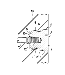
Fig. 4 is a longitudinal sectional view
illustrating said device as filling uP a recess left in
a concrete wall after removal of a seParator terminal.
A reference 4 designates a seParator as embedded in a
concrete wall 13. Said separator 4 is provided on its
opposite ends with threads 5 terminating in stoppers
12. respectlvelY.
13~21i~
A reference 14 designates a recess whlch has been
occupied bY the separator terminal havlng a head shaped
1n a truncated cone and left in the concrete wall 13
after removal of such seParator terminal.
It should be understood here that the expression
"concrete wall" covers the walls of varlous concrete
structures so far as theY are constructed wlth use of
the separators.
Now it will be described how to use the device of
the present invention.
After removal of the molds and the seParator
terminals upon comPletion of the concrete wall 13 bY
placing concrete, the recesses are left in the concrete
wall at positlons correspondlng to the resPective
separator terminals. The device 3 of the present
invention Is to fill uP each of these recesses 14. To
achieve It, the device _ Is Inserted, with Its
diameter-reduced portlon ahead, into the recess 14 so
that the threaded hole 6 Is aligned contact with the
threaded end of the separator 4, then a suitable tool
is engaged in the tool receiving means 7 and therebY
the main bodY I is rotated so as to engage the threaded
hole 6 thereof with the thread 5 of the separator 4.
In a consequence, as seen in Flg. 4, the main bodY I of
the device a is threaded on the end of the seParator 4
and secured within the recess 14. The bottom Plate 9
13~tZ114
-12-
of the elastic water-swollen rubber cylindrical
component 18 is tightlY Pressed along its pro~ecting
edge 11 particularly against the bottom surface of the
recess 14 as the main bodY 1 is threaded in whlle sald
elastlc water-swollen rubber cylindr~cal comPonent 8 is
compressed between the bottom surface of the recess 14
and the step 2 of the main bodY 1 and therebY radial 1Y
expanded so as to be Pressed agianst the Peripheral
surfaces of both the recess 14 and the main body 1. In
this manner. the device _ PerfectlY fills up the recess
14.
With a consequence, anY qUantitY of rainwater or
like Penetrating thorugh the surface of the wall 13
into a gap defined between the recess 14 and the
peripheral surface of the main bodY 1 of the device
is dammed uP by the elastic water-swollen rubber
cYlindrical comPonent 8 against further penetration
into the wall 13.
More speclfically~ when anY quantitY of rainwater
or like reaches said gap defined between the recess 14
and the Peripheral surface of the main bodY 1. said
elastic water-swollen rubber cylindrical comPonent 8 is
so swollen that the oPposite end surfaces thereof are
pressed against the bottom surface of the recess 14 and
the steP 2 of the main bodY 1. resPectively~ and
thereby its axial swelling is Prevented. As a result,
~3(~211~
-13-
said elastic water-swollen rubber cylindrical comPonent
8 is now radially swollen tightly against the
peripheral surfaces of both the recess 14 and the main
body I and reliably fills up the gaP defined between
the recess 14 and the device _, assisting the device _
to Prevent the quantity of water Present in said saP
from further penetrating into the wall 13.
Figs. 5 through lO illustrate other embodiments of
said device a.
In the device al of Fig. 5 constructed as the
second embodiment, the Projecting edge 11 formed on the
bottom plate 9 of the elastic water-swollen rubber
cYlindrical component 8 as the Part of the device a is
replaced bY an annular rldge 111 extending along the
perlpheral edge on the outer side of the bottom Plate
9.
The devlce a2 f Fig. 6 constructed as the third
embodiment differs from the device al as the second
embodiment in that said annular ridge 111 of the
elastic water-swollen rubber cYlindrical comPonent 8 is
disPosed~ instead of along the Peripheral edge. along a
circle concentric with said Peripheral edge and having
a radius smaller than that of said Peripheral edge on
the outer side of the bottom Plate 9.
In the device a3 of Fig. 7 constructed as the
fourth embodiment. the proiecting edge 11 formed on the
13~:114
-14-
bottom plate 9 of the elastic water-swollen rubber
cYlindrical component 8 ls replaced bY a pluralitY of
concentric annular ridges 112 each having a triangular
cross-sectlon extending along the peripheral edge on
the outer side of the bottom plate 9.
In the device a4 of Fig. 8 constructed as the
fifth embodiment, the bottom Plate 9 of the elastic
water-swollen rubber cYlindrical comPonent 8 is flat
without the pro~ecting edge or like.
The device a5 of Fig. 9 constructed as the sixth
embodiment differs from the device a4 as the fifth
embodiment in that there is provided an annular ridge
113 on the diameter-reduced end surface of the main
bodY 1 in said fifth embodiment.
The device a6 f Fig. 10 constructed as the
seventh embodiment differs from the device a4 as the
fifth embodiment in that the bottom plate 9 is removed
from the elastic water-swollen rubber cYlindrical
component 8 of said fifth embodiment and the diameter-
reduced end of the cYlindrical component extends
forwards beYond the diameter-reduced end surface of the
main bodY I so as to form a proiection 114.
These devices a1. a2. a3, 4 5 6
constructed as the second through seventh embodiments
function in the manner similar to the device _ as the
first embodiment.
l;~5~2:1~ 4
With the above-mentioned devices a, al, a2. a3,
a4. a5 and a6. the dlameter-reduced end surface of the
elastic water-swollen rubber cYlindrical comPonent 8
can be pressed against the bottom surface of the recess
in the annular line contact mode as the main bodY l of
each device is threaded on the end 5 of the seParator
4. Owing to such annular line contact, the diameter-
reduced end surface of the device can be tishtlY
pressed agianst the bottom surface of the recess 14
even when the main bodY I is rotated with a relativelY
small force.
The device a7 constructed in accordance with the
eighth embodiment and illustrated bY Figs. 11 through
13 corresponds to the device 3 as the first embodiment
in which the bottom Plate 9 Is removed from the elastic
water-swollen rubber cYlindrical comPonent 8 so that
the diameter-reduced end surface of said elastic water-
swollen rubber cYlindrical component 8 coincides with
the diameter-reduced end surface of the main bodY 1.
This eighth embodiment is identical to the first
embodiment in its operation and effect. SpecificallY.
as seen in Fig. 13. the device a7 secured within the
recess 14 bY threading the main body 1 on the end 5 of
the separator 4 and the outer peripheral surface of the
cylindrical comPonent 8 is Pressed against the inner
peripheral surface of the recess 14 while the opPosite
~3~Z1~4
-16-
end surfaces there of are Pressed against the bottom
surface of the recess 14 and the step 2 of the main
bodY 1. respectivelY~ In this manner, the device a7
fllls uP the recess 14.
The device of the present invention for fillins uP
the recess left in the concrete wall after removal of
the separator terminal provides significant effects as
follow:
(I) The feature that the device is threaded on
the end of the separator by a suitable tool assures
reliable and firm installaiton thereof, preventing the
device from be~ng disPlaced outwards and from fallins
off.
(2) The water-swollen rubber cyllndrical
component carried around the main bodY of the device is
compressed between the bottom surface of the recess and
the steP of the main bodY threaded on the end of the
separator and therebY radiallY exPanded tightly asainst
the Peripheral surfaces of both the recess and the main
bodY .
Therefore:
(a) The water-swollen rubber cylindrical
component is brought into contact with both the bottom
surface and the periPheral surface of the recess over a
sufficiently larse area to achieve a significant water-
sealing effect by said cylindrical component.
13~Z~
-17-
(b) Any quantitY of rainwater or like penetrating
through the wall surface into the gaP defined between
the Perlpheral surfaces of the recess and the main bodY
is dammed uP bY the water-swollen rubber cylindrical
component located outwardly of the main bodY against
further penetration into the wall.
(c) When anY quantity of rainwater or like
penetrating into the gaP between the periPheral
surfaces of the recess and the main bodY reaches the
water-swollen rubber cylindrical component, said
cYlindrical component is swollen, pressed at the
oPposite ends against the bottom surface of the recess
and the step of the main bodY. resPectively~ and
thereby prevented from being axlallY swollen. In
consequence, the cYllndrical component is radiallY
swollen tightlY agianst the PeriPheral surfaces of both
the recess and the main bodY over a sufficiently large
area to achieve a reliable sealing and therebY to
further assure that anY quantitY of water Present in
the saP defined therebetween is Prevented from further
penetrating into the wall.
(3) With the water-swollen rubber cYllndrical
component so arranged that the one end bears against
the steP of the main bodY and the other end extends
beyond the diameter-reduced end surface of said main
body when mounted around said maln bodY of the device,
13~21~4
-18-
the water-s~ollen rubber cYlindrical component is
compressed between the bottom surface of the recess and
the steP of the main bodY as said maln bodY of the
device is threaded on the end of the separator. Thus.
the cYlindrical comPonent is axiallY compressed and
thereby forciblY exPanded in the radial direction
futher tightlY against the periPheral surfaces of both
the recess and the main bodY.
(4) It ls effectivelY avoided by the invention
that rainwater or like penetrates through the wall
surface. then through the gap defined between the
recess and the device into the wall around the
separator. Therefore:
(a) The separator is prevented from being rusted
and thereby the durabilitY of the concrete structure is
improved.
(b) It is also effectivelY avoided that anY
quantity of rust containing water exudes over the wall
surface and injures the aesthetic appearance of the
wall surface.
(c) RelativelY small number of parts can be
easily assembled at a low cost into the device whlch
can be. in turn. easilY handled.