Note: Descriptions are shown in the official language in which they were submitted.
13(~Z33~
-- 1 --
CONVEYOR CARRIAGE
1 The invention relates to a conveyor carriage of the type for
an overhead conveying system having a proximity-readable
code carrier provided on the conveyor carriage.
A conveyor carriage of this type is known from DE-GM 85 35
331. The code carrier employed in this known conveyor
carrier is a computer-readable label (Bar code) or comprises
a number of cams or the like. Code carriers of this type
can only be applied to one side surface of the conveyor
carriage, so that they can be read or scanned from the
1~ respective side. This requires the conveyor carriage to
always travel along the rails at the same orientation, and
the reding or scanning apparatus to be always mounted on the
same side of the conveyor rails.
In addition, the known code carriers are rather failure-
prone and can easily be damaged, for instance by an impact
of the conveyor carrier or when the latter is taken off the
rails for storage. These shortcomings reduce the usefulness
of the known conveyor carriage. Morever, when a recording
of the conveyor carriage is desired, the code carrier has to
be replaceably mounted on the conveyor carriage, resulting
in difficulties regarding the selection of the correct code
carrier for any given application.
If is an object of the invention to provide a conveyor
carriage including a code carrier the reading of which can
be more readily adapted to operational conditions and which
is protected from damage and erroneous encoding.
Accordingly, in one aspect, the invention provides a
conveyor carriage, particularly for an overhead conveying
system, including a proximity-readable code carrier provided
on said conveyor carriage, characterized by its construction
~'
13VZ334
1 as a housing for the accommodation therein of a code carrier
including an electronic circuit of the non-contacting
control type.
The employ of an electronic circuit of the non-contacting
control type as the code carrier permits the reading unit to
be mounted at any suitable location in accordance with
operational and space considerations. Circuits of this non-
contacting controllable type are generally known from prior
art. Electromagnetically controllable and inductively
1 coupled circuits are thus for instance known from
EP-A-0 101 125, EP-A-0 242 906 and EP-A-0 257 688.
These known circuits are practically maintenance-free, they
are only supplied, however, together with a disc- or box-
shaped housing to be attached to the structural componentsto be identified. The attachment of a code carrier housing
of this type to a conveyor carriage is out of the question,
however, since this would result in the same problems as in
the case of the prior-art conveyor carriage. The
construction of the conveyor carriage itself as the housing
for the circuit alone permits the latter to be disposed at a
location permitting it to be controlled or read from both
sides of the conveyor carriage while ensuring its reliable
protection from damage due for instance to collision of two
or more conveyor carriages.
In a preferred embodiment, the invention provides a conveyor
carriage as hereinabove defined characterized in that in the
case of a conveyor carriage comprising a stirrup hanger,
said code carrier is housed in said stirrup hanger.
The accommodation of the code carrier and the manufacture of
the stirrup hanger are considerably simplified by the
construction wherein said stirrup hanger comprises two shell
portions formed as a housing. More preferably, when said
code carrier is embedded in a filler mass particularly a
5 `.
13~Z334
- 2A -
l cast resin, the construction ensures the hermetically sealed
accommodation of the circuit and its protection from dust
and environmental influences.
The employ of an electromagnetically or inductively
controlled circuit is economically advantageous. In
addition, a circuit of this type is small enough for its
accommodation in the conveyor carriage according to the
invention.
The construction of a conveyor carriage as hereinabove
defined characterized in that in the case of employ of a
hybrid circuit and a coil acting as an antenna, said coil is
disposed substantially perpendicular to the conveying
direction; is effective to improve readability and
controllability.
In a further aspect the invention provides a conveyor
carriagel for an overhead conveying system, including a U-
shaped frame, two casters for engaging a rail for travelling
along a conveying direction, and a proximity-readable code
carrier, said casters being supported and connected to one
another by said frame, said frame being formed with an
interior cavity so that said frame forms a housing for the
accommodation into said U-shaped frame of said proximity-
readable code carrier to protect said proximity-readable
code carrier from damage, said proximity-readable code
carrier including an electronic circuit of the non-
contacting control type.
An embodiment of the invention shall now be described by way
of example with reference to the accompanying drawings,
wherein:
fig. 1 shows a side view of a conveyor carriage according
to the invention,
fig. 2 shows a front view of the conveyor carriage according
13(~33~
1 to the invention, and
fig. 3 shows a sectional view taken along the line III-III
in fig. 1.
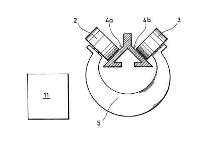
Figs. 1 and 2 respectively show a sideview and a front view
5 of a conveyor carriage 1 having a pair of casters 2 and 3
for travelling on a rail 4. Casters 2 and 3 are connected
to one another by a plastic stirrup hanger 5 so that their
axes extend at right angles relative to one another. Rail 4
has a substantially roof-shaped profile forming a support
10 surface 4a and 4b, respectively, for each castor 2, 3.
Stirrup hanger 5 is divided transversely of the conveying
direction along rail 4 and composed o~ two shell portions
5a and 5b. The two shell portions 5a and 5b are substant-
ially of the same shape, so that they can be cast or
15 injection-moulded in one and the same mould. The transverse
division of stirrup hanger 5 does not impair its rigidity
in the conveying direction.
At least one of the two shell portions 5a, 5b is formed
20 with an interior cavity 6 as shown in fig. 3. Inserted into
this cavity 6 is a ferrite core 7 having a coil 8 wound
thereon. Ferrite core 7 cooperates with coil 8 to act as an
antenna. Connector wires 9 connect coll 8 to a hybrid
circuit 10 acting as an information carrier. For the
25protection of hybrid circuit 10, ferrite core 7 with
coil 8 and connecting wires 9 from the influences of
climate, moisture and dust, the named components are
embedded in a cast resin completely filling cavity 6. For
facilitating assembly, particularly the touch-sensitive
0 hybrid circuit may be enclosed in a protective cover. After
the circuit has been thus embedded, the two shell portions
5a and 5b of stirrup hanger 5 are joined either releasably,
as by means of screws or detent members, or permanently,
as by means of an adhesive. In this manner stirrup hanger 5
forms a completely sealed housing for the code carrier.
The antenna, i.e. ferrite core 7 and coil 8, extends
substantially perpendicular to the conveying direction, and
lies substantially horizontal when casters 2 and 3 travel
~3~Z334
l on rail 4. A reading unit 11 is mounted ^t a suitable pos-
ition to the right or to the left of rai: 4, substantially
at the level of ferrite core 7.
When cGnveyor carriage 1 with its ferrite core 7 passes
5through a field generated by reading unit 11, a signal
corresponding to the informations stored in hybrid circuit
10 of the respective conveyor carriage 1 is generated for
display in reading unit 11 by an inducti~e coupling effect
(electromagnetic transmission), this signal permitting the
respective conveyor carriage 1 to be ide~tified without
having to be stopped. In addition, this -dentification
system composed of the circuit and the reading unit offers
the possibility of writing, i.e. the informations stored
in hybrid circuit 10 cannot only be read, but can also be
15rewritten or altered.
In a modification of the described and illustrated embodi-
ment, the housing for the code carrier may for instance
be formed by a carrier beam member exten~ing in the con-
20veying direction and interconnecting two stirrup hangerssupported on respective casters. When the antenna composed
of the ferrite core and the coil is disposed vertically and
perpendicular to the conveying direction~ the reading units
to be employed may be disposed above and~or below the
a5conveyor carriage. Any other orientation of the antenna
between the horizontal and the vertical Fositions is
likewise possible. If need be it is also possible to
provide two or more antennas, possibly at different
orientations. Instead of the described electromagnetically
30controllable and inductively coupled circuit it is also
possible to employ for instance an acoustically controllable
circuit (microphone circuit). If a highen expenditure in
terms of material is deemed acceptable, zt least the half
of the stirrup hanger not provided with the circuit may
consist of solid material. Finally, any castable plastic
compound may be used for embedding the circuit therein.