Note: Descriptions are shown in the official language in which they were submitted.
~l3~9~L
BACKGROUND OF THE INVEl~TI ON
3Field of the Invention
-
5The present invention relates to an explosive
6 detection system. Specifically, the present inv~ntion relates
7 to a detection system using thermal neutrons in combination with
8 a detector formed from an inorganic scintillator such as a
9 scintillator made of sodium iodide to provide for a more
efficient detection of explosives. A specific detection system
11 may be provided using a ring of detectors to detect the presence
12 of explosive within a particular plane of an object under
13 inspeCtiQn and with a continuous movement of the object
14 providiny for a three dimensional profile of the e~plosive.
~6Description of the Prior Art
.
17
1~A great need exists for the scanning of luggage,
19 baggage and other parcels for the detection of any explosive
material contained or concealed within their confines. For
21 example, a large number close to two million (2l000,000~ pieces
22 of luggage, are checked and/or carried onto aircraft daily by
23 close to seven hundred and fifty thousand (750,000) passengers
24 within six hundred (600) airports extending across the countryO
Many more packages move through the mails or are shipped to
26 sensitive buildings. There is a possibility, albeit smallg that
27 any one piece of luggage or parcel might contain explosive
28 material. It is, therefore, desirable to protect the public by
29
31
~2 1 ,
~3~2~
1 providing detection systems to scan the luygage and parcels to
Z detect the presence of any explosive material.
4 It thereby follows that any system of checking luggage
or parcels must have a very high probability of detection in
6 order to be effective. Because of the large number of parcels
7 processed, a high throughput is necessary for practicality. In
8 addition, any detection system because of the large number of
9 scanned items, is bound to occasionally give a false alarm. The
probabilit~ of these false alarms must be minimized in order to
11 provide for an effective explosive detection system. This is
12 true since when an alarm occurs it is not known, at that time,
13 whether it is true or false. This means that each time an alarm
14 occurs, a passenger or parcel must be detained for further
investigation. If false alarms are signif icantly high the
~ nuisance level and the delays could be unacceptable to the
17 public. It is, therefore, important that any explosive
18 detection system must have a very high probability of detection,
19 a high throughput rate, and yet at the same time, have a very
low probability of false alarms~ These conflicting criteria
21 have hampered efforts in the past to build a reliable and usable
22 system~
23
24 In general, prior art systems have not met the desired
characteristics of having a high probabil;ty of detection with a
26 low probability of false alarms at acceptable throughput rates.
27 As an example, one such prior art system is shown in Patent No.
28 3,832,545. This patent provides for a system for the detection
29 of nitrogen, which is generally present in the explosive
materials to be detected. The object under observation is
31
32
~3~2~
1 positioned within a cavity structure and with the object
2 bombarded by thermal neutrons~ The thermal neutron~ interact
3 with any nitrogen contained in the object to induce the emission
4 of gamma rays at an energy level characteristic of the nitrogen
element.
7 The emitted gamma rays are then detected by two
8 parallel planar arrays of ga~na ray detectors~ Patent No.
9 3,832,545 specifically provides for the use of li~uid or plastic
type organic scintillator detectors having an end surface for
11 viewing a portion of the article being inspected and with the
12 length of the organic scintillator being substantially greater
13 than the effective diameter of the end surface. As described in
14 this prior art patent, the array of organic scintillators
provides for a crude two aimensional profile of the nitrogen
~6 content within the object being inspected. The two dimensional
17 concentration profile of thë nitrogen i5 then used to provide
18 for a detection of an explosive. This type of prior art system
19 has a number of deficiencies, including both a low gamma ray
intensity and spatial resolution of the detection of the
21 concentration of the nitrogen contained in the object under
22 inspection, and the ins~nsitivity of the system to detect
23 explosive devices which are deliberately positioned ~ithin the
Z4 object under inspection so as to defy detection. Because of the
use of liquid or plastic type scintillator, long times are
26 required to make a decision about any object. The system
27 described in the prior art patent is also slow and cumbersome in
2~ operation which is a further limitation to its usefulness.
29
31
32 ' '
~3~
1 Other types of prior art explosive detection systems
2 depend upon the prior seeding of explosive materials with a
3 tracer material, such as a radioactive tracer. Althouyh this
4 type of system could be very useful if all explosive material
were manufactured with such tracer material, because of the
6 large amount of explosive material which has already been
7 manufactured and because of the difficulty of controlling the
8 manufacture of all explosive material so as to contain such
9 tracer material, this type of system is not practical. A usable
system must be able to detect the presence of explosive material
11 of a conventional type and of an unconventional type, whether
12 disposed within an object either in its original manufactured
13 form, or if deployed within the object so as to attempt to
14 con~use or evade the detection system. The prior art systems
have not met these various criteria and cannot produce the
~6 desired high probability of detection with the relatively low
17 production of false alarms.
18
19 An acceptable response to the explosive threat to
aviation, mails, or shipping requires detection techniques that
21 are highly sensitive t specific, rapid and non intrusive. The
22 efficient detection of nitrogen, at this point, offers the best
23 overall solution~ It is, therefore, important that this
24 detection of nitrogen be provided to give the maximum
information of the physical parameters of the explosive, such as
26 density and spatial distribution. The use of nuclear based
~7 techniques which subject the luggage or parcels to thermal
28 neutrons can be the basis of a system to produce the desired
29 results, but this system cannot be based on the prior art
techniques. It is important that the intensity~ energy and
P31
~2
2~
1 spatial distribution of the detected radiations from the object
2 under observation must ~e provided in such a way so as to help
3 to determine the presence or absense of explosives and this has
4 not yet been accomplished.
6 In addition to high detection sensitivity and low
7 false alarm the detection of the explosive should be independent
8 of the specific configuration and must be non-intrusive in order
9 to protect privacy. The detection equipment, of course, must be
non-hazardous to the contents of the checked items and to the
11 operating personnel and environment. Other more general
12 criteria are that the system must be reliable, easily maintained
13 and operable by relatively unskilled personnel and that the cost
14 must be low enough so as to be non-burdensome to airlines and
airports. Finally, it is desirable, when all other requirements
~6 achieved that the size of the system be relatively small so that
17 the system may be useful in a wide variety of environments.
1~ .,
19 In addition to the nuclear based systems des~ribed
above, non-nuclear systems have also been investigated. These
21 systems have achieved relatively high efficiencies of
22 detection, but generally have relatively high false alanm rates
23 and have long screening times. These type of non-nuclear
24 systems, therefore, by themselves cannot achieve the desired
results~ It is possible to combine a non nuclear system with a
26 nuclear system, but the present invention is directed to
27 specific improvements in the nuclear based type of system.
28
29 In order to develop a proper explosive detection
system, an understanding is required oE the properties of the
31
~2
~3~25;91~.
1 various explosives relevant to the specific techniques to be
2 used. Although there are a large number of explosive types, a
3 general classification into six major groups with minor
4 variations, has been proposed. The proposed classification
scheme includes the follo~ing types of explosives: (1)
6 nitroglycerine based dynamites, (2) ammonium nitrate based
7 dynamites, (3) military explosives, (4) homemade explosives, (5)
8 low order powders, and (6) special purpose explosives.
Nitroglycerine based dynamites are the most common
11 form of explosives. The basic composition includes equal
12 amounts of nitroglycerine and ethylene glycol dinitrate, plus a
13 desensitizing absorber in the form of cellulose in either sodium
14 or ammonium nitrate.
16 The ammonium nitrate based dynamites have been
17 replacing nitroglycerine based dynamites in popularity. These
18 types of dynamites are commonly referred to a~ slurries or
19 water gels. The two general types of ammonium based dynamites
are the cap-sensitive and the cap-insensitive types. The former
21 consists of aluminum, ammonium nitrate, ethylene glycol and
22 water ~hile the latter contains wax or fuel oil and water.
23
24 Military explosives are formed of Composition-4 (C-4),
TNT and picric acid. C-4 is composed of cyclotrimethylene
26 trinitramine ~RDX) and a plasticizer.
27
28 Homemade explosives are d;verse and are limited only
29 by the creativity of the perpetrator. Ammonium nitrate
31
32
~1 3~
1 (fertilizer) and fuel oil are the most cor~on and available
2 constituents.
4 Lo~ order powders (black and smokeless) have typically
been assemblea in pipe bomb configurations and have been used
6 ex-tensively in that form. Black powder contain potassium
7 nitrate, carbon and sufur. Smokeless powder is primarily pure
8 nitrocellulose or a mixture of nitrocellulose and
9 nitroglyerine.
11 Special purpose explosives include detonating cords,
12 blasting caps and primers. The explosive entities in the
13 special purpose explosives are PETN, lead azide, lead
14 styphanate, mercury fulminate and blasting gel.
~6 In general, all of these explosives contain a
17 relatively high amount of nitrogen ranging from nine to thirty
18 five percent by weight. The nominal density of these explosives
19 is typically 1.6 g/cm3 and with ranges between 1.25 to 2
g/cm3 or more. These physical properties demonstrate tha~ the
21 most unique signature of explosives is the high concentration
22 and ~ensity of the nitrogen content. There are other physical
23 factors that identify explosives, but these other factors do not
24 form part of the present invention. ~owever, one factor which
is important is that most explosives have a minimum progagation
26 thickness or diameter in order to be effective. The minimum
27 propagation thickness entails a sizable contiguous body o~
2~ explosives in the other two dimensions. This information i5
29 useful to the detection of explosives without making a specific
assumption of the actual shape of the explosiveO
31
32
~L3~ 5~
1 In can be seenV therefore, that a nuclear detection
2 technique can provide for the detection of the nitrogen content
3 to reliably indicate the presence of a large nitrogen content.
4 However, the frequent occurance of nitro~en in non-explosive
materials limits the level of detection sensitivity and merely
6 detecting the presence or absence of nitrogen alone is not
7 suf~icient. Therefore, a~ditional information is required
8 beyond simply sensing the presence of the nitrogen. The present
9 invention provides for this additional information using
specific structures and a specific detection configuration to
11 provide for a greater reliability in the detection of
12 explosives.
13
14 SUMMARY OF TEIE PRESENT INV13NTION
~6 The basis for the explosive detection system of the
17 present invention is the use of neutrons from a radioisotope or
18 an electronic neutron generator which neutrons are then slowed
19 down to create a cloud of low energy thermal neutrons wi~hin a
cavity. The luggage or other parcels pass through the cavity
21 and the thermal neutrons react with the variety of nuclei in the
22 luggage or parcels and produce characteristic high energy gamma
23 rays wh;ch may then be detected by external detectorsO The
24 detector processing electronics then converts the detected
signals into pulses suitable for computer processing.
26
27 The present invention relates to the specific
28 arrangement and type of the detectors relative to the use of
29 thermal neutrons as a source to provide the proper information.
The information may then be converted by computer process;ng to
31
32
~3~
1 indicate the possible presence of an explosive threat. At a
2 minimum, if there is a high enough count rate indicating the
3 presence of a great deal of nitrogen, the system of the present
4 invention can easily detect the presence of an explosive. The
system of thé present invention can also detect explosives
6 provided in more unconventional configurations and at the same
7 time reduce the number of false alarms to a relatively low
8 level. The prior art detector systems in general provide for
9 the gross detection, but cannot provide for the more sensitive
detection of the unconventional configurations while at the same
11 time, provide for a relatively low level of false alarms.
12
13 The explosive detection system of the present
14 invention includes the use of efficient inorganic scintillators
capable of resolving closely spaced high energy gamma ray lines~
~6 Specifically, sodium iodide scintillators are used to provide
17 for detection, but it is to be appreciated that other inorganic
18 scintillators such as cesium iodide, bismuth germanate and
19 barium floride scintillators may also be used. In addition,
inorganic solid state detectors such as lithium~drifted
2~ germanium, high purity germanium or mercuric iodide may be
22 used.
23
24 The inorganic scintillators of the present invention
are arranged to form at least one ring of detectors so as to
26 provide for a detection of a plurality of slices or parallel
27 successive planes of the object nder inspection as the object
28 is moved continuously through the ring of detectors. In a
29 specific embodiment of the invention9 this ring is broken into
sets of C-rings; and in order to provide for a better three
31 dimensional representation, two spaced sets of C-ring detectors
32
~30~Siig~
1 may be used with the open ends of the C-rings facing each other
2 so as to pr~vîde for a detection completely around the object
3 and with the plurality of successive planes building up a three
4 dimensional profile of the object under inspection.
6 The system of the present invention is capable of
7 scanning a continuous flow o luggage and parcels. In addition,
8 the operation of the system may be fully automatic so that the
9 system does not depend on operator experience or interpretation
and thereby provides for an automatic dètection of explosives.
11 .
12 BRIEF DESCRIPTION OF THE DRAWINGS
13
14 A clearer understanding of the present invention will
be seen with reference to the following description and drawings
16 wherein
17
18 Figure 1 illustrates a perspective view of a luggage
19 and parcel inspection system;
21 Figure 2 illustrates the system of Figure 1 with a
22 shield portion of the system removed;
23
24 Figure 3 illustrates a detailed view o a conveyer
path for the system showing the positioning of a pair of thermal
neutron sources and sets of inorganic scintillator detectors
27 constituting the C-ring detector array;
28
29 Figure 4 illustrates a block diagram of the system
showing the detection of part;cular gamma rays for detecting of
31
32 1. ,
- 10 -
~3~
1 explosive material and with waveforms ~a), (b) and (c)
2 representative of the signals at particular points in the
3 system; and
~'igure 5(a~, (b) and (c) illustrate typical spatial
6 profiles of nitrogen concentration for explosive and
7 non-explosive materials.
9 DESCRIPTION OF THE PREFERRED EMBODIMENT
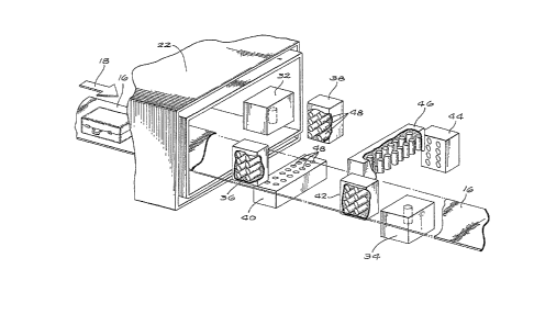
11 As shown in Figure 1, an explosive detect;on system 10
12 includes a loading station 12 (which may consist of a scale to
13 weigh the luggage) and an unloading station 14 (which may
14 consist o~ a diverter to separate the alarmed lugguge Erom the
rest). The loading station leads to a continuous conveyer belt
~6 16 which extends from the loadiny station 12 to the loading
17 station 16 and has a continuous motion as indicated by the
18 arrows 18. A central shield structure 20 encloses the explosive
19 detection system and wit~ two external wing portions 22 and 24
extending from the central structure 20 to encloses the conveyer
21 belt 16 leading from and to the loading and unloading stations
22 12 and 14.
23
24 As can be seen in Figure 2, wherein the shields 20, 22
and 24 are removed~ the explosive detection system is positioned
26 over a central portion of the conveyer belt 15. Speciically,
27 the explosive detection system includes a cavit~ structure 26
28 through which the conveyer belt 16 passes. As shown in Figures
~9 1 and 2, various articles of luggage and parcels may be
positioned on the loading station 12 and may then be carried
31
32
~,
~IL3q~2S~L
l through the cavity 26 to the unloading station 14 by the
2 conveyer belt 16.
4 The cavity 26 is formed by external wall members
including a top wall 28, side walls 30 and 31 and a bottom wall
6 (not shown) which is positioned below he conveyer ~elt 16.
7 Extending through the wall members are thermal neutron sources,
8 such as source 32, positioned at the top of the cavity and as
9 shown in Fi~ure 3, neutron source 34 spaced from the neutron
source 32 and positioned at the bottom of the cavity. Also as
ll- shown in Figures 2 and 3, detector structures are positioned to
12 form two C-rings of detectors having their opened ends facing
13 the neutron sources. This may be seen in Figure 3 wherein the
14 side detector structures 36 and 38 together with the bottom
l~ detector structure 40 are all associated with the neutron source
~6 32. Sim;larly, side detector structures 42 and 44 together with
17 the top detector structure 46 are all associated with the
18 neutron source 34.
19 . . .. . . . . .
As shown in Figure 3, the side detector structures are
21 provided by two sets of four detectors located in each side
22 detector structure 36 and 38. The bottom detector structure 40
23 includes two sets of seven detectors. The detectors associated
24 with the neutron source 34 similarly include two sets of four
detectors located in each side detector structure 42 and 44 and
26 with two sets of seven detec~ors located in the top detective
27 structure 46. The detectors associated with the neutron source
28 32, therefore, form a C-ring of detectors having the opened
29 portion of the C facing upward. In an opposite fashion the
3Q detectors associated with the neutron source 34 form a C-ring
31
~2
- 12
~L31D:~59~L
1 with the opened portion of the C facing downward. The
2 combination of the two sets of C-ring detectors thereby provide
3 for the detection of- a complete ring around the object under
4 inspection to produce a better three dimensional pro~ile of the
nitrogen distribution within any particular object passing
6 through both sets of detectors.
~ It is to be appreciated that the invention is
9 described with reference to the use of two C-ring detector
structures and with each C-ring including two sets of parallel
11 rows and columns of detectors.~ It should be appreciated that
12 only a single C-ring structure may be used with only a single
13 row and column of detectors. The use of the additional parallel
14 sets of detectors improves the visualization of the profile of
the concentration of nitrogen, but a simpler system could be
~6 used with a single C-ring and single rows and columns of
17 detectors. It is also to be appreciated that more detectors
18 could be used. A full ring of detectors could also be placed
19 out of the plane of the source, around the cavity.
21 The actual structure of the neutron source and its
22 environment, such as the structures 32 and 34, may be of any
23 type. For example, the neutron source may be a radioisotope
24 (such as 252Cf) or an electronic neutron source (such as (D,D~
or (D,T) generators). By collisions, mostly with the nuclei of
26 the selected materials surrounding the source the neutrons are
27 slowed down to create a cloud of low energy thermal neutrons
28 within the cavity. The low energy thermal neutrons specifically
29 interact with the variety of nuclei in the luggage or parcel.
The interaction of the low energy thermal neutrons produces
31
32
1 characteristie high energy gamma rays which are detected by the
2 external rows and columns forming the C-ring deteetors.
4 Each detector in the rows and eolumns preferably are
formed of inorganie seintillators. Speeifically, all of the
6 detectors, such as represented by a detector 48, may be formed
7 of an inorganie seintillator material, such as sodium iodide
8 (NaI). Other inorganie materials may be used and as an example,
9 inorganie materials such as cesium iodide (CsI), bismuth
germanate (BGo-Bi4 Ge3 12) or barium fluoride (BaF2)
11 also may be usèd to provide for the detector structure. In
12 addition inorganie solid state detectors sueh as lithium-drifted
13 germanium (Ge(Li)), high purity germanium (HPGe) or mercurie
14 iodide (~gI2) may be used. The particular details of a
speeifie detector strueture do not form a part of the present
~6 invention, but the speeifie use of an inorganie seintillator
17 with good energy resolution and effieieney to deteet gamma rays
1~ produced by thermal neutrons provides for a unique detection of
19 nitrogen and/or other elements do form a part of the present
invention.
21
22 Although inorganic seintillators have been used in the
23 past with thermal neutrons, this use was not or the detection
24 of nitrogen in explosives, but rather to provide for the
detection of ehlorine, iron, chromium, ete. as a background
26 component and not specifically for the detection of the nitrogen
27 component and spatial distribution of the explosive material.
28 Other uses of inorganie seintillators have been in combination
29 with fast neutron sources so as to detect nitrogenO but this
different type of neutron source provides for a different type
31 of detection.
32 1 ,
13~2~
l The present invention contemplates the specific
2 combination of a thermalized neutron source with an inorganic
3 scintillator, such as a sodium iodide detector. This specific
4 combination provides for the capability of resolving closely
spaced high energy gamma ray lines and specifically for
6 detecting the particular gamma ray lines representative of the
7 nitrogen content of explosives. These particular high energy
8 gamma rays lines occur at 10.8 MeV. The inorganic scintillator
9 detector is used because it is a very efficient detector and
because it provides acceptable features in a number of areas.
ll These areas include level of total countrate r the shape of the
12 detector, availability of detector, reliability and cost. It is
13 to be appreciated that the inorganic scintillator may also be
14 used to detect other elements representative of an explosive.
~6 As indicated above, the currently preferred inorganic
17 material is sodium iodide, but other inorganic materials may be
18 used. For example, bismuth germanate has a higher effective
l9 atomic number because of the bismuth and a higher density tha~
the sodium iodide. The efficiency of a bismuth germanate
21 scintillator is, therefore, higher than that of sodium iodide.
22 ~owever, bismuth germanate scintillators are in~erior to sodium
23 iodide in energy resolution and the cost for a bismuth germanate
24 ~ scintillator is much higher than that for sodium iodide and it
also has a background component that can interfer with the
26 nitrogen signal. ~owever, both of these inorganic structures
27 are superior to the organic scintillators used in the prior art
28 devices.
29
For example, on the basis of the mean free path of 1D
31 MeV gamma rays, sodium iodide and bismuth germanate are roughly
32
_ ~5 _
~3~2~
1 6 and 11 times more efficient than organic scintillators
, 2 Moreover, in terms of depositing the gamma energy in the
¦ 3 scintillators, sodium iodide and bismuth germanate are
1 4 roughly 10 and 40 times respectively more efficient than organic
scintillators. The energy resolution, which is the ability to
6 separate two lines, given as the peak's width at half the peak's
1 7 height, is around 200 to 300 KeV for sodium iodide and 400 to
8 500 KeV for bismuth germanate at high energies and with the
9 range depending on the crystal size and quality.
I ll The main advantage of the prior art organic
12 scintillators, which may k~ plastic or liquid, is their very
13 fast time response permitting exceedingly high count rates.
14 Because of the very high count rates, a high background from
lS other neutron reactions can be handled easily and thereb~
¦ ~6 eliminating the need for sophisticated cavity design. Another
1 17 advantage of the organic scintillators is their relatively low
18 cost and ease of manufacture. Even with these advantages with
l9 the use of organic scintillators, the use of the inorganic
scintillators of the present invention, and specifically in the
~ 21 particular C-ring configuration, provides for a hiyher
; 22 resolution and thereby a more efficient detection of any
23 explosive materialO The organic scintillators are inefficient
24 detectors for high energy gamma rays and their gamma
spectroscopical qualities are poor. Organic scintillators
26 thereby have poor energy resolution and make the separation
27 between nitrogen and deleterious signals, such as occur with C1,
28 Fe, Cr or Ni, very dif~icult.
29
As can be seen in Figure 3, any item to be scanned,
31 such as a piece of luggage, passes through the cavity on the
32
~3gD~9~
1 conveyor 16 and is subjected to the thermal neutrons produced
2 by the therlnal neutron source 32. At successive positions of
3 the piece of luggage, the individual detectors 4~, forming the
4 row 40 and columns 36 and 38, provide for a cross sectional
profile of any material containing nitrogen. The C-ring o~
6 detectors thereby provides for a two dimensional slice or plane
7 of the nitrogen concentration and with a three dimensional
8 profile built up by the successive slices produced as the
9 luggage moves through the C-ring o detectors.
11 The two dimensional plane provided by the detector
12 structures 36, 38 and 40 has less resolution at the upper end
13 since the C-ring is not complete. Although a detector structure
14 could also be provided along the upper surface of the cavity
such detector structure could interfere with the production of
~6 therm~l neutrons by the source 32 of such neutrons. A more
17 eficient way of complet;ng the ring is to have a second
18 C-shaped group of detector structures provided downstream of the
19 first group so that the luggage moves from the irst C~ring of
detector structures to the second C-ring of de~ector structures
21 and with the open ends of the C-rings in the first and second
22 sets being opposite to each other. The inormation from the two
2~ sets of C-rings o detector structures may be merged
24 electronically in a computer to provide for a complete picture.
As indicated above, this picture forms a three dimensional image
26 of the container such as the luggage and its contents by
27 building up the successive slices or planes of information.
28
29 Figure 4 illustrates in general the detection of the
information by any one of the individual detectors 48. As shown
31
32 ' '
- 17 -
5~
1 in Figure 4, neutrons from the sources, either 32 or 34, are
2 thermalized and impinge on a piece of luggage or parcel as
3 represented by the block 50. The individual detectors 48
4 forming the C-ring detector structures, each detect the
producticn of gamma rays. The reaction between the thermal
6 neutrons and the nitrogen in the explosive or other material, is
7 as follows:
14 1 15
9 N ~ n ~ N +
7 0 7
The first factor in the above equation is the nitrogen
12 in the explosive or other material within the luggage. For
13 example, wool, cotton, etc. all contain nitrogen. The nitrogen
14 when bombarded with thermal neutrons, as shown by the second
factor, produces nitrogen in a changed form (another isotope of
~6 nitrogen) plus gamma rays, of which approximately 14% are at
17 10.8 MeV. Each gamma ray as detected by a detector 48 produces
18 an output from the detector as shown in waveform (a) in Figure
19 4. As can be seen, the detector 48 produces an output signal
having a height "h" and with this signal decaying exponentially
21 to zero value at approximately one micro second. The detectors
22 48 are supplied with a high voltage from a high voltage source
23 52. The height "hn and the area under the decaying signal are
24 both proportional to the gamma ray energy.
26 The output from each detector 48 is passed directly or
27 through a preamp and amplifier 54 to produce an outpu~ signal a~
28 shown in waveform (b) in Figure 4O It can be seen that the
2g ind;vidual gamma ray is converted from the exponentially
decreasing signal to a pulse signal having a height n~ which is
31
32
- 18 -
~l3~259~
1 proportional to the area under the signal shown in waveform (a).
2 It is to be appreciated that each yamma ray received by each
3 detector 48 produces successive signa~s representing the
4 concentration of nitrogen.
6 The output from the preamp~amplifier 54 is passed
7 through an analog to digital (A to D) converter 56 to produce a
8 digital number representing the height "H" of the waveform (b)
9 of Figure 4. It can be seen, therefore, that the outputs from
the A to D converters 56 are a series of digital numbers
11 representing the detec~ion of-gamma rays representing the
lZ concentration of nitrogen. A small range of the digital numbers
13 correspond to the gamma rays of interest. As more and more
14 gamma rays are detected at each detector, the digital number
from the A to D converters 56 at each point in time is counted.
16 The counts of each ~igital number which occurs, which is
17 proportional to the number of nitrogen gamma rays incident on
18 the detector, are then coupled into a computer 58 for
19 computation of a profile for each slice or plane of the object
under observation and for the production of a three dimensional
21 representation of the concentration of nitrogen of the ob3ect~
22 Waveform (c) illustrates the profile of the spectrum received by
23 the detectors 48 and with the space 60 between the two lines
24 representing the area of interest, more specifically the gamma
rays representing nitrogen.
26
27 Figures 5~a), (b) and (c~ illustrate typical profiles
28 for explosive material in a block form, non-explosive materials,
29 such as a wool coat or jacketg and explosive material in sheet
form. As can be seen in Fi~ure 5~a), which represents the
31
32
; - 19 -
~L3~2~
l detection from one column of detectors at four successive,
2 planes as the object moves past the dectectors, the high
~ readings of 12 in two successive planes and 8 in a third
4 successive plane, represent a high concentration of nitrogen
rich material probably representive of a block of explosive
6 material. The detectors in the Qther column and along the row
7 would confirm the presence of such block material. The large
8 difference between readings in the profile of Figure 5(a) show
g an unusual density of nitrogen material not typical in other
types of items which contain nitrogen.
11
12 For example, Figure 5(b) illustrates an item such as a
13 wool coat or suit which may contain a relatively high amount of
14 nitrogen, but with the nitrogen spread out in a diffuse pattern
which would not be representative of an explosive material.
~6 Although the overall nitrogen content of the w~ol article is
17 quite high, the concentration does not reach the levels of
18 explosive material.
19
Figure 5(c) illustrates an explosive material in a
21 sheet form along one side or edge of the luggage and again, the
22 concentration o~ nitrogen and high readings relative t~ the
23 lower readings indicates the presence of something having a
24~ ` relative high concentration of nitrogen, plus a relatively high
density for this concentrationL This again would typically be a
26 profile of an exp~losive materialO The computer 589 therefore;
27 may be programmed to identify such specific profiles and
28 provide for an alarm such as through an alarm 62 so that the
29 luggage or parcel may be subjected to a more thorough
inspection.
31
32
,
- 20 -
~.3~2~
1 The present invention is, therefore~ directed to an
2 explosive detection system using thermalized neutrons from a
3 source to impinge on an object potentially containing explosive
4 material and with the thermal neutrons reacting with the
nitrogen contained in the object to produce gamma rays. The
6 gamma rays are detected by inorganic scintillators and in a
7 preferred embodiment, the scintillators are arranged in a ring
8 configuration to provide for detection of a two dimensional
9 slice or plane of the object under observation. The object is
moved continuously through the ring of detectors so that
11 successive slices or planes provide for the build up of a three
12 dimensional profile of the nitrogen bearing material within the
13 object under observation. The three dimensional profile may
14 then be used to provide for a determination of the concentration
and distribution of the nitrogen bearing material to make a
~6 determination whether such nitrogen bearing material has a
-17 profile likely to be an expiosive material, such as high
18 nitrogen density.
1~
In a preferred embodiment, the inorganic scintillator
21 is sodium iodide and with two oppositely disposed C-ring
22 detectors having their open ends facing each other to provide
23 for a complete profile of each slice or plane along all four
24 sides. In addition, the detectors may be formed of sets of
detectors in rows and columns to increase the detection
26 capability by receiving additional gamma rays produced by the
27 interaction of the thermal neutrons and nitrogen in the cavity.
28 The present invention~ therefore t provides for a greater
29 resolution and efficiency in the detection of potentially
explosive material and with khis accomplished in a fast period
31
~2
- 2~ -
~3t)~
1 of time so as to provide for an adequate throughput of the
2 luggage or parcels through the detection system.
4 Although the invention has been desc~ibed with
reference to a particular embodiment, it is to be appreciated
6 that various adaptations and modifications may be made and the
7 invention is only to be limited by the appended claims.
11 ` - .
12
13
14
~6
17
18.
19
21
22
23
24
26
27
28
29
31
32
- 2~ -