Note: Descriptions are shown in the official language in which they were submitted.
~3~2S~ '
BACRGROUND OY T~ INVENTION
The present invention is directed to a beam generating
system for electron beam measuring instruments, particularly, a
beam generating system for electron beam measuring instruments
having an electron accelerating electrode, a control electrode, a
directly heated boride cathode an~ a holding part for the
absorption of the retaining forces generated by the clamping
mechanism.
Prior art beam generating systems are disclosed, for
example, in J. Vac. Sci. Technol. 15 (4), 1978, pages 1554
through 1560 (in particular, see page 1558, FIG. 7) and in German
patent DE 31 50 848. The life expectancy of lanthanum hexaboride
(LaB6) crystals used as cathodes in these beam generating systems
is limited by their thermically disadvantageous mount. As a
consequence of a temperature gradient existing between a tip o
the crystal and a sllan~ of the crystal, an increased evaporation
rate occurs in the region of the mount in comparison to the
tip. The evaporation rate destroys the mechanical stabllity of
the cathode ~see, for example, Scanning Electxon Microscopy,
1985/4, pages 1327 through 1338, particularly page 1331, FIG.
6a~.
SUMMARY GF T~E INVENTIO~
. . . _ .
An ohject of khe present invention is to provide a beam
generating system of the type initially cited having a
thermically and mechanically improved cathode mount. The present
invention provides a beam generating system for electron beam
measuring instruments having an electron accelerating electrode,
a control electrode, a directly heated boride cathode and a
holding part for the absorption of the retaining forces generated
, -2
~3~ZS~2 203~5 2813
by the clamping mechanism. The holding part is located im-
mediately under electron-emitting regions of the boride cathode.
According to a broad aspect of the invention there
is provided a beam generating system for electron beam measuriny
instruments having an electron-accelerating electrode, a
control electrode, a directly heated boride cathode having a
tip for emitting electrons and a cathode mount that has a
clamping mechanism, the clamping mechanism contacting the
boride cathode via a means for holding comprising the means
for holding located immediately under the tip for emitting
electrons of the boride cathode.
According to another broad aspect of the invention
there is provided a beam generating system for electron beam
measuring instruments having an electron accelerating electrode
for accelerating electrons in an electron beam, a control
electrode, and a directly heated boride cathode having a tip
for emitting electrons and held in a cathode mount that has a
clamping mechanism, the clamping mechanism contacting the
boride cathode ~ia a means for holding, comprising -the means
for holding located immediately under and adjacent to the tip
for emitting electrons of the boride cathode.
According to another broad aspect of the invention
there is provided a beam generating system for electron beam
measuring instruments having an electron accelerating electrode
for accelerating electrons in an electron beam, a control
electrode and a directly heated lanthan hexaboride cathode
having a tip for emitting electrons and held in a cathode mount
that has a clamping mechanism, the clamping mechanism contacting
the ca-thode via a means for holding, comprising the means for
holding located immediately under the tip for emitting electrons
31~2S~
20365-2813
of the eathode, the means for holding being composed of two
graphite cubes for contacting opposed sides of the cathode.
The advantage obtainable wi-th the present invention
is that the life expectancy of a boride cathode can be notice-
ably enhanced. Further, a si~nificantly lower power is required
for heating the eathode to the required operating temperature.
BRIEF DESCRIPTION OF THE DRAWING
The features of the present invention whieh are
believed to be novel, are set forth with particularity in the
appended claims. The invention, together with further objects
and advantages, may best be understood by reference to the
Eollowing description taken in conjunction with the accompanying
drawing, and in whieh:
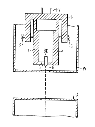
The single Figure shows the schematic structure of
a beam generating system of the present invention.
DESCRIPTION OF THE PREFERRED EMBODIMENT
A beam generator for electron beam measuring
instruments, particularly scanning electron microscopes and
electron beam testersl schematically shown in the Figure, is
essentially composed of an anode A usually being at a grounded
potential, of a control electrode W (for example, a Wehnelt
electrode) and of a directly heated boride eathode BK that a
mount H holds centered in an opening of the control electrode
W. The control electrode W is negatively biased in comparison
to the cathode BK. The mount H has kwo set screws S and a clamp-
ing mechanism composed of two metallic clamps K. This clamping
mechanism transmits the retaining forces generated by the set
- 3a -
~3~25~ `
screws S onto the two graphite cubes G located immediately below
the tip of the lanthan hexaboride (~aB6) crystal of the cathode
BK. As a consequence of this thermically and mechanically
beneficial mount, only a low heating power of, for example~ 10
watts is needed in order to bring the boride cathode BX, which is
in a high vacuum (10 6 through 10 7 Torr), to the required
operating temepexature range of about 1200 C to 1800C. A
filament voltage is supplied to the system via the terminal posts
~V to provide a cathode potential of about ~3 kV through -30 kV.
The inventive mount of the cathode BK guarantees that
the LaB6 crystal is only insignificantly hotter at the clamping
location than it is at the electron-emitting tip. A considerably
lower evaporation rate results r particularly at crystal faces
lying opposite the graphite cubes G, in comparison to prior art
cathode mounts which have a high temperature difference between
their crystal tips and crystal shanks in the region of the
electrical contacts. The electrical contact is also preserved
for a longer operating period of the cathode BK. Moreover, its
mechanical stability is not deteriorated by a reduction of the
crystal cross section above the clamping location which can be
observed in prior art systems.
The invention is not limited to the particular details
of the apparatus depicted and other modifications and
applications are contemplated. Certain other changes may be made
in the above described apparatus without departlng from the true
spirit and scope of the invention herein involvedO It is
intended, therefore, that the subject matter in the above
depiction shall be interpreted as illustrative and not in a
limiting sense.