Note: Descriptions are shown in the official language in which they were submitted.
~3~
DISPLAY CARTON FOR HOLDING UPRIGHT ARTlCLES
Field of the Invention
This invention relates to display cartons. ~ore
particularly, it relates to a display carton for holdin~ relatively
thin articles on ed~e while havin~ the capability to carry and
display other articles of different shape.
Background of the Invention
Display cartons are used to package articles so that
shoppers can view the contents of the carton without openin~ it.
Many different types of articles are packaged in this way, usually
requirin~ different carton designs for each different type of
product. Products of unusual siæe or shape can make the task of
desi~ning a display carton very difficult, sspecially when the
package should be as compact and inexpensive as possible and yet
I5 present the articles in an attractive, appealin~ manner. When
products of different size and shape are packaged in the same
display carton the problems are understandably multiplied.
Despite the problems encountered in packaging different
types of products in the same display carton, there are some groups
of different but related products which should be packaged together
if at aLl possible. For example, picnic plates and cups are
generally bou~ht at the same time, but because of their ~reatly
different siæe and shape are usually packaged in separate cartons.
It would be desirable to package both the plates and cups in the
same display carton so that customers would be able to view the
entire set together. The cost of such an arrangement, however, must
be low enough to make the display carton practical.
Brief Summary of the Invention
This invention provides a display carton having front, back
and end panels foldably connected to a bottom panel. A top panel
foldably connected to the front panel terminates short of the back
panel. The space between the front and back panels is adapted to
receive relatively thin articles standing on edge, and the space in
the interior of the carton bounded by the front, end and top panels
is adapted to receive articles of different shape. The top panel
13~3;~
may contain a cutout through which the upper portions of the
different shaped articles can protrude, and the front panel may
contain a cutout through which the articles can be viewed. In
addition, means are provided to hold the top panel in place in
spaced relationship to the back panel.
The design of the display carton permits the carton to be
fabricated quite inexpensively, as will be explained further
hereinafter.
Other features and aspects of the invention, as well as its
various benefits, will be made clear in the more detailed
description of the invention which follows.
Brief Description of the Drawin~s
FIG. 1 is a plan view of a production blank from which the
display carton of the present invention can be fabricated;
FIG. 2 is a pictorial representation of the blank of FIG.l,
showing the front and back panels and the dust flaps in folded
condition;
FIG. 3 is a pictorial representation of one of the end
panels of the carton as it would appear in an interim stage of
formation;
FIG. 4 is a view similar to that of FIG. 3, but showing the
end panel after it has been fully formed;
FIG. 5 is a transverse sectional view of the end panel
taken on line 5-5 of FIG. 4;
FIG. 6 is a pictorial representation of the next step in
fabricating the display carton of the present invention following
the formation of the end panels;
FIG. 7 is a view similar to that of FIG. 6, but showing the
top panel as it is being moved into locking position over stacks of
cups to be contained in the carton;
FIG. 8 is a plan view of the display carton of the present
invention after it has been fully formed;
FIG. 9 is a transverse sectional view of the carton, taken
along line 9-9 of FIG. 8, showing a stack of cups supported therein;
and
13~ 9'~1
FIG. 10 is a pictorial representation of the fully
fabricated display carton of the present invention, showing a stack
of plates supported on end between the top and back panels and also
showing stacks of two different sizes of cups in the interior of the
carton.
Description of the Invention
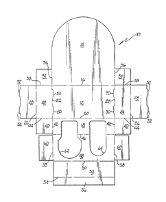
Referring to FIG. 1, a display carton blank 10, typically
formed of paperboard, comprises a bottom panel portion 12 connected
to a relatively large back panel portion 14 along fold line 16, and
to a relatively short front panel portion 18 along fold line 20.
Also connected to the bottom panel portion 12 along fold lines 22
are end panel portions 24, which in turn are connected by fold lines
26 to end flaps 28. The fold lines 22 contain two slits 30 which
extend slightly inwardly into the bottom panel portion 12, and the
end flaps 28 contain two short tabs 32 adapted to oe inserted into
the slits 30 in a manner to be explained hereinafter.
Dust flaps 34 are foldably attached to the back panel
portion 14 along fold lines 36, which are generally extensions of
the fold lines 22. The dust flaps are separated from the end panel
portions 24 by slits 38, which are generally extensions of the fold
line 16. Similarly, dust flaps 40 are foldably connected to the
front panel portion 18 along fold lines 42, which are also generally
extensions of the fold lines 22. The dust flaps 40 are separated
from the end panel portions 24 by slits 44.
Connected to the front panel portion 18 along fold line 46
is top panel portion 48, which at its opposite end is connected
along fold line 50 to intermediate back panel portion 52. The
intermediate back panel portion 52 in turn is connected at its
opposite end along fold line 54 to locking flap 56. The purpose of
this arrangement will be made clear hereinafter.
Connected to the ends of the top panel portion 48 along
fold lines 58 are top panel end flaps 60. Spaced inwardly from the
fold lines 42 and 58 is a cutout 62 which extellds through portions
of both the front panel portion 18 and the top panel portion 48.
The purpose of the cutout is to hold in place articles positioned in
~30~
--4--
the inter;or of a carton formed from the blank 10 and to permit the
articles to be viewed on display. In like manner a ~enerally
similar but smaller cutout 6~l is inwardly spaced from the other fold
lines 42 and 58 to hold smaller articles in place and to permit them
S to be viewed.
Referrin~ to FIG. 2, the blank is shown in the first steps
of being folded into carton form. The back panel 14 has been folded
up about fold line 16, and the front panel 18 has been folded up
about fold line 20. Also, dust flaps 34 and 40 have been folded in
about their fold lines 36 and 42, respectively, to lie in a plane
substantially at right angles to the front and back panels. The end
panel portions 24 and the end flaps 28 at this stage are still in
their flat unfolded condition.
As shown in FIG. 3, which illustrates one of the end panels
at the next sta~e of its formation, after the dust flaps 34 and 40
have been folded in toward each other, the end panel 24 is folded up
against the outer faces of the dust flaps. As shown in FIG. 4, the
next step is to fold the end flap 28 down against the inner faces of
the dust flaps. The short tabs 32 extendin~ from the ends of the
end flaps 28 mate with the slits 30 in the bottom panel 12 to lock
the end panel construction in place. The resulting configuration is
illustrated in FIG. 5, wherein the dust flap 34 is shown to be
sandwiched between the end panel 24 and the end flap 28. It will be
understood that the opposite end panel would be of the same
construction.
Referring now to FIG. 6, the psrtially formed carton is
shown after the end panel construction has been formed but before
the front and top panels 18 and 48 have been fixed in place. At
this stage, the articles to be contained in the interior of the
carton are placed on the bottom panel prior to folding the top panel
down to cover the interior space. Thus, in usin~ the display carton
of the present invention to package paper or plastic cups, the cups
C1 and C2 are placed on the bottom panel 12 in alignment with the
cutouts 62 and 64 in the front and top panels. As illustrated, the
cups C1, which typically would be drinkin~ cups, are the larger of
13~ 3'3'~
-5-
the two sizes and are arranged in stacked condition aligned with the
larger cutout 62. The smaller cups C2, which typically would be
fruit cups, are arranged in a stack i.n alignment with the smaller
cutout 64. The number of cups to be packaged obviously may vary.
Eight cups in a stack would be a comn~on arrangement.
As shown in FIG. 7, the next step in the formation of the
display carton is to fold the top panel 48 down about its fold line
46. The top panel end flaps 60 would first have been folded down
about their fold lines 58 to form a right angle with the top panel
in order to fit inside the end panel structure when the top panel is
folded down. During this step, the narrower portions of the stacked
tapered cups may penetrate the cutouts in the top panel to protrude
therethrough. The dimensions of the cutouts are coordinated with
the dimensions of the cups so that there is not enough space
surrounding the protruding cup to allow the wider portion of the cup
located beneath the top panel to pass through the cutout. The cups
are thus held in place inside the carton.
Still referring to FIG. 7, the intermediate back panel 52
is then folded down about its fold line 50 and the locking flap 56
is folded up about its fold line 54 prior to moving the intermediate
back panel and the locking flap into their final positions.
Continued movement of the top panel down into place will move the
intermediate back panel into a vertical position spaced from the
back panel 14 a distance substantially equal to the width of the
locking flap 56. The intermediate back panel 52 thus forms the back
wall of the carton interior in which the cups are located, and the
space between the back panel 14 and the intermediate back panel 52
is the space in which the thin articles, such as paper or plastic
plates, can be stacked on edge.
This arrangement is more clearly depicted in FIGS. 8 and 9,
which show the carton after it has been fully erected with the cups
Cl and C2 contained therein. Although for purpose of clarity the
storage space between the back panel 14 and the intermediate back
panel 52 is shown to be empty, it should be understood that the
space is ready to receive articles to be displayed. As best
~13~3 o ~
;llustrated in FIG~ 8, the base portions of the tapered cups C1 and
C2 protrude through the top panel ~l8 but the wider portions adjacent
the rims of the CUp5 do not. This arran~ement allows the cups to
extelld upwardly for a limited distance for display purposes, but
keeps the cups from falling out of the carton. The slloulder
portions 66 on the cutout associated with the lar~er cups Cl result
in the top panel 48 having a wider portion between the end panel 24
alld the cutout 62 than would be the case if the cutout were to
extend strai~ht out to the front panel 18 in the manner of the
cutout 64. This precludes an area of potential weakness from
developing along the fold line between the top and front panels when
a wide cutout is provided. -
~
FIG. 9 more clearly shows the locking flap 56 extendingfrom the bottom of the intermediate back panel 52 into contact with
the back panel 14. The combination of the flap width, the
flexibility of the paperboard flap, and the biasing tendency of the
fold 50 to push the intermediate back panel 52 toward the back panel
14 creates a frictional wedging action between the flap and the back
panel. This wedging mechanism holds the entire front, top and
intermediate back panel assembly securely in place. Also visible in
this view is the far top panel end flap 60, the back ed~e of which
~cts as a backing or support for the intermediate back panel 52.
The near top panel end flap, not visible in the view, also provides
a similar function. The cutout in the front panel terminates short
of the bottom panel to provide a lip which prevents the cups from
extendin~ through the cutout beyond the front panel.
As shown in FIG. 10, the display carton 10 when erected and
loaded with a set of picnic plates and cups would contain two
different sizes of cups C1 and C2 as well as plates P, standing on
edge and supported on the bottom panel in the space between the back
panel and the intermediate back panel. The back panel can be any
convenient height, provided it is tall enou~h to afford adequate
support for the plates.
It should now be clear that the present invention provides
a carton that can contain and hold in place different sizes of cups
t2~
as well as a stack of plates, while displayin~ the contents to
customers. The carton is inexpensive to produce, bein~ fabricated
from a ninimum of paperboard material without costly time consumin~
~luin~ operatiolls. It is held in erected form by a novel frictional
S wedgin~ support arran~ement which creates the plate receiving space
between the back panel of the car~on and the intermediate back
panel. Obviously, if desired, the cup sizes can be the same and the
number of stacks of cups and correspondin~ cutouts is not limited to
two.
It should be obvious that althou~h a preferred embodiment
of the invention has been described, chan~es to certain specific
details of the preferred embodiment can be made without departing
from the spirit and scope of the invention.