Note: Descriptions are shown in the official language in which they were submitted.
~3~
The invention relates to electric cable terminals
consisting of two elements, one of which is a metal part to
be secured to the cable lead while the other is acting as
an insulating sleeve bearing the cable marking elements. These
elements are assembled by axial sliding and the sleeve can
rotate with respect to the metal element for a better
orientation and easy reading of the marking elements.
Terminals which can take on various shapes according
to connection requirements are already well known and include
lO prod, clip-on, ring, spade, and fork types, as well as
"Faston" (Trade Mark) (male-female) terminals. These terminals
are marked according to various well known marking techniques.
According to currently adopted techniques, one end
of the metal component is incorporated by melting into the
insulating element of these terminals, as described in the
French Patents 2477305 and 1468859 and in the European Patent
00345460.
These known solutions have two main drawbacks, i.e.
20 the metal element and insulating sleeve are firmly assembled
and will not permit rotation of the sleeve after connection,
for a better and easier identification of the cables.
The second drawback is due to the fact that it is
difficult to secure the metal component to the cable lead,
which requires a special crimping tool. In this case the
insulating part of the envelope is also involved in the
crimping procedure and may be deformed or even become useless,
especially if recessed for introduction of sleeve marker rings.
To prevent crimping damage, the insulating part is now
13~31~i~
manufactured in Polyvinyl Chloride since this material
has excellent flexibility and crushing strength. No other
plastic materials can be used for this purpose since they
cannot withstand crimping stresses.
According to the Italian Patent No.12505 A/86,
the first drawback was eliminated by rotating the metal
component with respect to the insulating sleeve, but the
cecond drawback still remained to be solved.
European Patent No. 0117166 is also known, according
to which the terminal is made from flat die-cut shapes which
are progressively bent so as to surround the cable lead.
However, this approach has also several disadvantages. In
the first place, it prevents the sleeve from being rotated
in order to ensure easy reading of the markings. Then, there
is the fact that this system requires special tools for
deformation of the flat links and for application of the
envelope and this equipment must be used on the site where
the cables are connected, thus involving discomfort for
the operator and loss of time. Furthermore, it seems that
this system is only used for prods, to the exclusion of all
other terminal types.
This invention has the aim to eliminate all these
drawbacks of known terminals and of their manufacturing
systems and to make available an implementation system for
any kind of terminals which will ensure that the sleeve can
be turned with respect to the fixed metal component while
ensuring that crimping of the metal element on the lead will
absolutely not involve the insulating sleeve. Furthermore,
the terminal according to the invention will simplify its
~3~J31~
application, since the metal element and sleeve are
separately manufactured and are assembled by axial sliding
in two subsequent stages, i.e. first to thread the cable
and fastening the latter by crimping onto the lead, and
then a final stage in which the sleeve will cover the
connection between the metal component and the leaa.
According to this invention, the metal component
is fitted with a mechanism for connection to the electrical
appliances (prod, fork, ring, Faston (Trade Mark)and the
like; this mechanism being coupled by a first ring-shaped
zone which then continues, at the end opposite the connecting
mechanism, by a second equally ring-shaped but slightly more
open zone, so that it will be peripherally projecting. The
insulating element has essentially a hollow tubular shape
with two internal annular steps which determine, together
with the second-ring shaped zone, the two axial sliding
positions The cable markings are visible on the outside
of the insulating sleeve and marking may be performed according
to well known systems, for instance by means of ring-shaped
marking elements introduced in a transparent recess.
These features result in a terminal of new structural
and functional design by which the markings can be turned for
easy identification and the metal element can be crimped onto
the lead without involving the insulating sleeve which will
then cover the connection. This solution will also make the
connection of cables to equipment or appliances easier for the
operator.
The various features of novelty which characterize
the invention are pointed out with more particularity
:~3U31~i~
in the claims annexed to and forming a part of this disclosure.
For a bet-ter understanding of the invention, its operating
advantages and specific objects attained by its use, reference
should be had to the accompanying drawings and descriptive
matter in which there are illustrated and described preferred
embodiments of the invention.
IN THE DRAWINGS
Figures 1, 2 and 3 respectively show a vertical section,
a top view and a horizontal section of the metal component of
a fork-shaped connection in accordance with the invention;
Figures 4 and 5 respectively show a view from left
and right of the metal component illustrated in Fig. l;
Figure 5 shows a vertical longitudinal section of the
insulating element fitted, for illustrative purposes, with a
system of ring-shaped marking elements;
Figures 9, 10 and 11 show the progressive assembly
stages of the terminal on a cable;
Figure 12 shows a view from the right of the terminal
illustrated in Fig. 11;
Figures 13 and 14 show terminals with other marking
systems, and r
Figures 15, 16 and 17 show a top view of the metal
component of the terminal with different connecting devices.
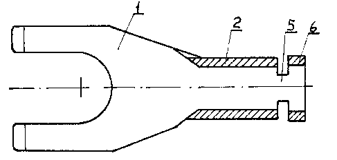
With reference the drawings, the device 1 is adapted
to be coupled to an electrical equipment or appliance. For
instance, device 1 may be a fork. This device is connected to
the zone 2 which forms a closed ring having a diameter consistent
with the diameter of the lead 3 of cable 4 and long enough to
permit crimping as described hereinafter.
~3V3~
This initial zone 2 is connected by a narrow lower
link 5 to a second zone 6 of limited width forming a slightly
open ring, so that this second ring 6 is slightly projecting
with respect to the first ring 2.
The insulating element 7 has a hollow tubular shape
and in-ternally features from left to right, i.e. starting from
the connecting mechanism, a flaring 8, forming a first step
9, a slight annular recess lO having the same width as the
second ring 6, a second step ll, and an end section 12 having
about the same diameter as the annular zone 6. The cable
marking will appear on one side of this sleeve, as exemplified
in the Figures 6, 7 and 8 and by means of ring shaped marking
elements 13, introduced in a transparent longitudinal recess
14.
After having thus defined the metal and insulating
components, the two parts are assembled as shown in Fig. 9,
by fitting the second annular shaped zone 6 into the first
section of the sleeve 7, initially causing a deformation of
the bellmouth 8 and the first step 9, until this second ring
shaped zone snaps into the annular recess 10 where it remains
locked through the action of the first step 9.
In these conditions, the operator will have access
to the terminal and can fit it on the cable featuring the bare
lead 3. The operator will then thread this lead into the first
ring 2 of the terminal and will use special pinchers for
deformation of the ring 2 into 2' thus securing the cable
to the terminal as shown in Fig. 10. This operation is easily
completed and will not affect the insulating envelope according
to the objectives of the invention.
13U3~
Subsequently, the opera-tor will push the sleeve 7
towards the connecting mechanism 1 until the sleeve 7 covers
the terminal/conductor coupling zone, as shown in Figure 11.
By the latter operation, the second annular zone 6 fits into
the end section 12 resting against the second step 11 of the
sleeve 7.
Figures 11 and 12 clearly show that the metal
component and the insulating element always remain reciprocally
independent although there may be a slight friction between
the two elements. This means that the sleeve 7 can freely
rotate in the direction of the arrows F shown in Figure 12,
so that the identification code can be located in the best
position for easy reading, according to the objectives of
the Invention.
As explained above, the insulating sleeve 7 may
provide for cable marking in various modes. Mention has already
been made of ring shaped marking elements 13, fitted into a
longitudinal recess 14, but the markings 15 may also be
directly printed or stamped on the sleeve as shown in Figure 13,
or code labels 17 may be introduced in the slot 16 as shown
in Figure 14. Any marking system may be used for the terminal
of the invention.
The device to be connected to the electric equipment
or appliance may also be of any design.
For instance, Figures 1 through 12 feature a fork or
"spade" type connector 1 for exemplification purposes. However
this device may also be ring-shaped 18 as shown in Figure 15,
or a prod 19, as shown in Figure 16, or a male or female
Faston (Trade Mark) 20, as shown in Figure 17, or a hook, or
the like. 13~)31~
Obviously, the first and second annular shaped
zones may be replaced by complete rings without notches,
although the second ring 6 will always have a slightly larger
diameter than the first ring 2.
The foregoing is a description of a preferred
embodiment of the invention which is given here by way of
example only. The invention is not to be taken as limited
to any of the specific features as described, but comprehends
all such variations thereof as come within the scope of the
appended claims.