Sélection de la langue

Search

Sommaire du brevet 1303168 

Énoncé de désistement de responsabilité concernant l'information provenant de tiers

Une partie des informations de ce site Web a été fournie par des sources externes. Le gouvernement du Canada n'assume aucune responsabilité concernant la précision, l'actualité ou la fiabilité des informations fournies par les sources externes. Les utilisateurs qui désirent employer cette information devraient consulter directement la source des informations. Le contenu fourni par les sources externes n'est pas assujetti aux exigences sur les langues officielles, la protection des renseignements personnels et l'accessibilité.

Disponibilité de l'Abrégé et des Revendications

L'apparition de différences dans le texte et l'image des Revendications et de l'Abrégé dépend du moment auquel le document est publié. Les textes des Revendications et de l'Abrégé sont affichés :

  • lorsque la demande peut être examinée par le public;
  • lorsque le brevet est émis (délivrance).
(12) Brevet: (11) CA 1303168
(21) Numéro de la demande: 1303168
(54) Titre français: CONNEXION A DEUX ELEMENTS INDEPENDANTS CONCUS POUR UNE COOPERATION PAR GLISSEMENT
(54) Titre anglais: ELECTRICAL CABLE TERMINAL CONSISTING OF TWO INDEPENDENT ELEMENTS TO BE ASSEMBLED BY AXIAL SLIDING
Statut: Durée expirée - après l'octroi
Données bibliographiques
(51) Classification internationale des brevets (CIB):
  • H01R 4/18 (2006.01)
  • H01R 43/20 (2006.01)
(72) Inventeurs :
  • PIANA, IVANA (Italie)
  • PIANA, SILVANO (Italie)
(73) Titulaires :
  • GRAFOPLAST S.P.A.
(71) Demandeurs :
  • GRAFOPLAST S.P.A. (Italie)
(74) Agent: MARKS & CLERK
(74) Co-agent:
(45) Délivré: 1992-06-09
(22) Date de dépôt: 1988-06-15
Licence disponible: S.O.
Cédé au domaine public: S.O.
(25) Langue des documents déposés: Anglais

Traité de coopération en matière de brevets (PCT): Non

(30) Données de priorité de la demande:
Numéro de la demande Pays / territoire Date
12503 A/87 (Italie) 1987-06-19

Abrégés

Abrégé anglais


ABSTRACT OF THE DISCLOSURE
An electrical terminal has two elements, one of
which is formed by a metal coupling device, a first ring
connected to the coupling device and a second ring connected
to the first ring by means of a narrow lower link, so that
the second ring is externally projecting beyond the first
ring, and the other element is formed by a hollow, tubular
insulating sleeve internally featuring a flaring forming an
initial step, followed by an annular recess, a second step
almost centrically located with respect to a cylindrical end
section, and assembled by introducing the second ring in
the sleeve until it is positioned in the annular recess and
resting against the first step. After connection to the lead
by crimping the first ring, the sleeve is moved axially so
as to cover the coupling zone, i.e. until the second ring
fits into the end portion of the sleeve against the second
step.

Revendications

Note : Les revendications sont présentées dans la langue officielle dans laquelle elles ont été soumises.


The embodiments of the invention in which an exclusive
property or privilege is claimed are defined as follows:
1. A cable terminal comprising an elongated metal conducting
element and an elongated tubular insulating sleeve, wherein said
elongated metal conducting element comprises;
a first end termination in means for connection to an
appliance or equipment and an opposed cable receiving end;
first ring means for securing a cable lead to said
conducting element, said first ring means having a length and
internal and external diameters and being positioned between said
ends of said conducting element; and,
second ring means for locking said conducting element in
said insulating sleeve, said second ring means being positioned
at the cable receiving end of said conducting element, said
second ring means being spaced apart from and aligned with said
first ring means, said second ring means having an external
diameter larger than that of said first ring means;
said elongated tubular insulating sleeve comprises first and
second opposed ends and an internal bore extending from said
first end to said second end, said bore having a first portion
having a diameter substantially the same as the external diameter
of said first ring means and a second portion having a diameter
substantially the same as the external diameter of said second
ring means;
an internal annular wall defined by the transition from said
first portion of said bore to the second portion of said bore;
an internally directed flaring at said first end of said
sleeve, and,
-8-

an annular recess positioned between said flaring and said
first portion of said bore, said annular recess having a length
substantially the same as the length of said first ring means and
having a diameter smaller than the external diameter of said
second ring means;
whereby when said second ring means of said conducting
element is inserted into the first end of said sleeve past said
flaring of said sleeve, it temporarily mates with said annular
recess of said sleeve while a wire lead is secured to said first
ring means, said second ring means then being forced through said
first portion of said bore past said annular wall into said
second portion of said bore whereby said conduction element
becomes locked in said insulating sleeve.
2. The cable terminal according to claim 1, wherein the
connecting means comprises a fork, a spade, a ring, a prod, or a
faston-type connector.
3. The cable terminal according to claim 1, wherein the
insulating sleeve is provided with cable identification means.
4. The cable terminal according to claim 3, wherein the cable
identification means comprises a slot adapted for displaying a
cable marker.
5. The cable terminal according to claim 1, wherein the first
and second ring means of the metal element comprise closed rings.
6. The cable terminal according to claim 1, wherein the first
and second ring means of the metal element comprise split rings.
-9-

Description

Note : Les descriptions sont présentées dans la langue officielle dans laquelle elles ont été soumises.

~3~
The invention relates to electric cable terminals
consisting of two elements, one of which is a metal part to
be secured to the cable lead while the other is acting as
an insulating sleeve bearing the cable marking elements. These
elements are assembled by axial sliding and the sleeve can
rotate with respect to the metal element for a better
orientation and easy reading of the marking elements.
Terminals which can take on various shapes according
to connection requirements are already well known and include
lO prod, clip-on, ring, spade, and fork types, as well as
"Faston" (Trade Mark) (male-female) terminals. These terminals
are marked according to various well known marking techniques.
According to currently adopted techniques, one end
of the metal component is incorporated by melting into the
insulating element of these terminals, as described in the
French Patents 2477305 and 1468859 and in the European Patent
00345460.
These known solutions have two main drawbacks, i.e.
20 the metal element and insulating sleeve are firmly assembled
and will not permit rotation of the sleeve after connection,
for a better and easier identification of the cables.
The second drawback is due to the fact that it is
difficult to secure the metal component to the cable lead,
which requires a special crimping tool. In this case the
insulating part of the envelope is also involved in the
crimping procedure and may be deformed or even become useless,
especially if recessed for introduction of sleeve marker rings.
To prevent crimping damage, the insulating part is now

13~31~i~
manufactured in Polyvinyl Chloride since this material
has excellent flexibility and crushing strength. No other
plastic materials can be used for this purpose since they
cannot withstand crimping stresses.
According to the Italian Patent No.12505 A/86,
the first drawback was eliminated by rotating the metal
component with respect to the insulating sleeve, but the
cecond drawback still remained to be solved.
European Patent No. 0117166 is also known, according
to which the terminal is made from flat die-cut shapes which
are progressively bent so as to surround the cable lead.
However, this approach has also several disadvantages. In
the first place, it prevents the sleeve from being rotated
in order to ensure easy reading of the markings. Then, there
is the fact that this system requires special tools for
deformation of the flat links and for application of the
envelope and this equipment must be used on the site where
the cables are connected, thus involving discomfort for
the operator and loss of time. Furthermore, it seems that
this system is only used for prods, to the exclusion of all
other terminal types.
This invention has the aim to eliminate all these
drawbacks of known terminals and of their manufacturing
systems and to make available an implementation system for
any kind of terminals which will ensure that the sleeve can
be turned with respect to the fixed metal component while
ensuring that crimping of the metal element on the lead will
absolutely not involve the insulating sleeve. Furthermore,
the terminal according to the invention will simplify its

~3~J31~
application, since the metal element and sleeve are
separately manufactured and are assembled by axial sliding
in two subsequent stages, i.e. first to thread the cable
and fastening the latter by crimping onto the lead, and
then a final stage in which the sleeve will cover the
connection between the metal component and the leaa.
According to this invention, the metal component
is fitted with a mechanism for connection to the electrical
appliances (prod, fork, ring, Faston (Trade Mark)and the
like; this mechanism being coupled by a first ring-shaped
zone which then continues, at the end opposite the connecting
mechanism, by a second equally ring-shaped but slightly more
open zone, so that it will be peripherally projecting. The
insulating element has essentially a hollow tubular shape
with two internal annular steps which determine, together
with the second-ring shaped zone, the two axial sliding
positions The cable markings are visible on the outside
of the insulating sleeve and marking may be performed according
to well known systems, for instance by means of ring-shaped
marking elements introduced in a transparent recess.
These features result in a terminal of new structural
and functional design by which the markings can be turned for
easy identification and the metal element can be crimped onto
the lead without involving the insulating sleeve which will
then cover the connection. This solution will also make the
connection of cables to equipment or appliances easier for the
operator.
The various features of novelty which characterize
the invention are pointed out with more particularity

:~3U31~i~
in the claims annexed to and forming a part of this disclosure.
For a bet-ter understanding of the invention, its operating
advantages and specific objects attained by its use, reference
should be had to the accompanying drawings and descriptive
matter in which there are illustrated and described preferred
embodiments of the invention.
IN THE DRAWINGS
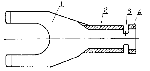
Figures 1, 2 and 3 respectively show a vertical section,
a top view and a horizontal section of the metal component of
a fork-shaped connection in accordance with the invention;
Figures 4 and 5 respectively show a view from left
and right of the metal component illustrated in Fig. l;
Figure 5 shows a vertical longitudinal section of the
insulating element fitted, for illustrative purposes, with a
system of ring-shaped marking elements;
Figures 9, 10 and 11 show the progressive assembly
stages of the terminal on a cable;
Figure 12 shows a view from the right of the terminal
illustrated in Fig. 11;
Figures 13 and 14 show terminals with other marking
systems, and r
Figures 15, 16 and 17 show a top view of the metal
component of the terminal with different connecting devices.
With reference the drawings, the device 1 is adapted
to be coupled to an electrical equipment or appliance. For
instance, device 1 may be a fork. This device is connected to
the zone 2 which forms a closed ring having a diameter consistent
with the diameter of the lead 3 of cable 4 and long enough to
permit crimping as described hereinafter.

~3V3~
This initial zone 2 is connected by a narrow lower
link 5 to a second zone 6 of limited width forming a slightly
open ring, so that this second ring 6 is slightly projecting
with respect to the first ring 2.
The insulating element 7 has a hollow tubular shape
and in-ternally features from left to right, i.e. starting from
the connecting mechanism, a flaring 8, forming a first step
9, a slight annular recess lO having the same width as the
second ring 6, a second step ll, and an end section 12 having
about the same diameter as the annular zone 6. The cable
marking will appear on one side of this sleeve, as exemplified
in the Figures 6, 7 and 8 and by means of ring shaped marking
elements 13, introduced in a transparent longitudinal recess
14.
After having thus defined the metal and insulating
components, the two parts are assembled as shown in Fig. 9,
by fitting the second annular shaped zone 6 into the first
section of the sleeve 7, initially causing a deformation of
the bellmouth 8 and the first step 9, until this second ring
shaped zone snaps into the annular recess 10 where it remains
locked through the action of the first step 9.
In these conditions, the operator will have access
to the terminal and can fit it on the cable featuring the bare
lead 3. The operator will then thread this lead into the first
ring 2 of the terminal and will use special pinchers for
deformation of the ring 2 into 2' thus securing the cable
to the terminal as shown in Fig. 10. This operation is easily
completed and will not affect the insulating envelope according
to the objectives of the invention.

13U3~
Subsequently, the opera-tor will push the sleeve 7
towards the connecting mechanism 1 until the sleeve 7 covers
the terminal/conductor coupling zone, as shown in Figure 11.
By the latter operation, the second annular zone 6 fits into
the end section 12 resting against the second step 11 of the
sleeve 7.
Figures 11 and 12 clearly show that the metal
component and the insulating element always remain reciprocally
independent although there may be a slight friction between
the two elements. This means that the sleeve 7 can freely
rotate in the direction of the arrows F shown in Figure 12,
so that the identification code can be located in the best
position for easy reading, according to the objectives of
the Invention.
As explained above, the insulating sleeve 7 may
provide for cable marking in various modes. Mention has already
been made of ring shaped marking elements 13, fitted into a
longitudinal recess 14, but the markings 15 may also be
directly printed or stamped on the sleeve as shown in Figure 13,
or code labels 17 may be introduced in the slot 16 as shown
in Figure 14. Any marking system may be used for the terminal
of the invention.
The device to be connected to the electric equipment
or appliance may also be of any design.
For instance, Figures 1 through 12 feature a fork or
"spade" type connector 1 for exemplification purposes. However
this device may also be ring-shaped 18 as shown in Figure 15,
or a prod 19, as shown in Figure 16, or a male or female
Faston (Trade Mark) 20, as shown in Figure 17, or a hook, or

the like. 13~)31~
Obviously, the first and second annular shaped
zones may be replaced by complete rings without notches,
although the second ring 6 will always have a slightly larger
diameter than the first ring 2.
The foregoing is a description of a preferred
embodiment of the invention which is given here by way of
example only. The invention is not to be taken as limited
to any of the specific features as described, but comprehends
all such variations thereof as come within the scope of the
appended claims.

Dessin représentatif
Une figure unique qui représente un dessin illustrant l'invention.
États administratifs

2024-08-01 : Dans le cadre de la transition vers les Brevets de nouvelle génération (BNG), la base de données sur les brevets canadiens (BDBC) contient désormais un Historique d'événement plus détaillé, qui reproduit le Journal des événements de notre nouvelle solution interne.

Veuillez noter que les événements débutant par « Inactive : » se réfèrent à des événements qui ne sont plus utilisés dans notre nouvelle solution interne.

Pour une meilleure compréhension de l'état de la demande ou brevet qui figure sur cette page, la rubrique Mise en garde , et les descriptions de Brevet , Historique d'événement , Taxes périodiques et Historique des paiements devraient être consultées.

Historique d'événement

Description Date
Inactive : Périmé (brevet sous l'ancienne loi) date de péremption possible la plus tardive 2009-06-09
Exigences relatives à la nomination d'un agent - jugée conforme 2007-03-30
Exigences relatives à la révocation de la nomination d'un agent - jugée conforme 2007-03-30
Inactive : Lettre officielle 2007-03-30
Demande visant la nomination d'un agent 2007-03-05
Demande visant la révocation de la nomination d'un agent 2007-03-05
Inactive : Grandeur de l'entité changée 2002-05-29
Accordé par délivrance 1992-06-09

Historique d'abandonnement

Il n'y a pas d'historique d'abandonnement

Titulaires au dossier

Les titulaires actuels et antérieures au dossier sont affichés en ordre alphabétique.

Titulaires actuels au dossier
GRAFOPLAST S.P.A.
Titulaires antérieures au dossier
IVANA PIANA
SILVANO PIANA
Les propriétaires antérieurs qui ne figurent pas dans la liste des « Propriétaires au dossier » apparaîtront dans d'autres documents au dossier.
Documents

Pour visionner les fichiers sélectionnés, entrer le code reCAPTCHA :


Pour visualiser une image, cliquer sur un lien dans la colonne description du document. Pour télécharger l'image (les images), cliquer l'une ou plusieurs cases à cocher dans la première colonne et ensuite cliquer sur le bouton "Télécharger sélection en format PDF (archive Zip)" ou le bouton "Télécharger sélection (en un fichier PDF fusionné)".

Liste des documents de brevet publiés et non publiés sur la BDBC .

Si vous avez des difficultés à accéder au contenu, veuillez communiquer avec le Centre de services à la clientèle au 1-866-997-1936, ou envoyer un courriel au Centre de service à la clientèle de l'OPIC.


Description du
Document 
Date
(aaaa-mm-jj) 
Nombre de pages   Taille de l'image (Ko) 
Page couverture 1993-10-31 1 12
Abrégé 1993-10-31 1 21
Revendications 1993-10-31 2 64
Dessins 1993-10-31 3 85
Description 1993-10-31 7 213
Dessin représentatif 2001-10-22 1 6
Correspondance 2007-03-05 2 73
Correspondance 2007-03-30 1 13
Correspondance 2007-03-30 1 17
Paiement de taxe périodique 1997-05-20 1 107
Paiement de taxe périodique 1996-05-17 1 81
Paiement de taxe périodique 1995-05-18 1 81
Paiement de taxe périodique 1994-05-19 1 81