Note: Descriptions are shown in the official language in which they were submitted.
1 ~3n~3~88
1 53,828
TRANSPORTATION APPARATUS
BACKGROUND OF THE INVENTION
Field of the Invention:
The invention relates in general to transporta-
tion apparatus, such as escalators and moving walks, and
more specifically to transportation apparatus having an
electrically controlled brake.
Descri~tion of the Prior Art:
My U.S. Patent 4,600,865, entitled Transportation
Apparatus, which issued July 15, 1986, describes and claims
transportation apparatus in which deceleration is directly
controlled when such apparatus is stopped. The direct
control of deceleration includes a deceleration servo loop
which provides a current signal for an inner current loop
which regulates brake current to cause the transportation
apparatus to stop at a predetermined constant deceleration
rate. In one embodiment of the invention set forth in my
U.S. patent, the running brake current, ie., the brake
current prior to the initiation of a controlled stop, is
also included in the servo loop, and regulated to a prede-
termined constant value. It was felt that by regulatingthe running brake current to a constant value, the brake
would always be fully lifted when the transportation
apparatus was in its normal running mode, compensating for
brakes which were sensitive to brake temperature and supply
voltage variations.
3~
88
2 53,828
Actual experience with an escalator having an
electrically controlled brake constructed as set forth in
my U.S. patent has proven that partial setting of the brake
can still occur during normal running conditions, notwith-
standing regulating the brake running current to a constantvalue.
SUMMARY OF THE INVENTION
~ riefly, the present invention relates to new and
improved transportation apparatus, and methods of operating
same, in which a brake is electrically controlled, to
permit controlled stops as set forth in the hereinbefore
mentioned U.S. patent. Further, the running brake current
is controlled to prevent partial setting or "dragging" of
the brake during normal operation of the apparatus.
Instead of regulating the running brake current
to a predetermined constant value, the running brake
current is regulated to provide an electromagnetic flux
which substantially cancels magnetic flux provided by
permanent magnets in the brake, notwithstanding a magnetic
flux value which changes with brake temperature. In
addition to the expected change in the resistance of the
brake coil with brake temperature, the permanent magnets,
which set the brake in the absence of a cancelling electro-
magnetic flux produced by the brake coil, were found to
provide a declining value of magnetic flux with increasing
brake temperature. In the present invention, the running
brake current is regulated to always provide the required
cancelling magnitude of electromagnetic flux at any temper-
ature over the operating temperature range of the brake, by
providing brake voltage feedback as well as brake current
feedback. The values of the brake voltage feedback and the
brake current feed back are selected to provide a ratio
which causes the brake current to change with brake temper-
ature according to the change in magnetic flux provided by
the brake magnets.
If the brake current is precisely regulated
according to the brake voltage and brake current feedback,
~30~188
3 53,828
the brake will always fully recover from a brake current
transient which causes momentary dragging of the brake.
The range of the ~rake current versus brake temperature
which will permit full recovery, however, i5 relatively
narrow, making the adjustment of the brake controller
somewhat critical. In a preferred embodiment of the
invention, this range of brake current is widened, signifi-
cantly reducing the criticality of setting the feedback
values, by pulsing the brake current during normal running
conditions. The brake current pulsing, which does not
change the average brake current, and which is terminated
at the start of a controlled stop of the apparatus, allows
the average brake current to be outside the critical narrow
range. The pulse magnitude is selected such that a
non-critical setting of the feedback ratio will always
cause a brake current pulse to intersect the narrow criti-
cal range of brake current. Thus, the brake will always
fully lift after each transient excursion of the brake
current into a brake current range which causes partial
setting or dragging of the brake.
A further improvement is provided by relating the
initial brake current pulse to initial release of the brake
upon start up of the transportation apparatus, to always
drive the brake current through the narrow critical brake
release range with the first brake pulse. This results in
the initial release of the brake being faster and with less
drag than it would be without brake pulsing, or with a
brake pulsing arrangement which does not control the
initial pulse.
A
1~0~188
3A
Accordinqly, in one aspect the invention provides
a method of operating transportation apparatus having a
conveyor driven by an electrical motor, an electrically
released, magnetically set brake having a brake coil and
permanent magnets, and a servo loop for regulating the
brake coil current, wherein the brake has hysteresis
caused by overlapping first and second brake current
release ranges for increasing and decreasing values,
respectively, of the brake current, with the overlapping
portions defining a narrow brake current relase window
which will cause release of the brake notwithstanding a
momentary brake current excursion into a brake setting
value outside either brake current excursion into a brake
setting value outside either brake current release range,
and wherein the brake coil and permanent magnets have
temperature dependent characteristics which cause the
upper and lower limits of the narrow brake current release
window to shift with brake temperature, the improvement
comprising; compensating for the temperature
characteristic of the brake while the electrical motor is
driving the conveyor to cause the regulated brake coil
current to change with the shifting brake current window,
said compensating step including the steps of; providing
both brake voltage feedback and brake current feedback for
the servo loop, and selecting the values of the brake
voltage feedback and brake current feedback to cause the
electromagnetic flux provided by the brake current to
substantially cancel the permanent magnet flux over the
operating temperature of the brake.
In a further aspect the invention provides a
transportation apparatus having a conveyor driven by an
electrical motor, an electrically released, magnetically
~303~l38
set brake having a brake coil and permanent magnets, and a
servo loop for regulating the brake coil current, wherein
the brake has hysteresis caused by overlapping first and
second brake current release ranges for increasing and
decreasing values, respectively, of the brake current,
with the overlapping portions defining a narrow brake
current release window which will cause release of the
brake notwithstanding a momentary brake current excursion
into a brake setting value outside either brake current
release range, and wherein the brake coil and permanent
magnets have temperature dependent characteristics which
cause the upper and lower limits of the narrow brake
current release window to shift with brake temperature,
the improvement comprising; means for compensating the
servo loop for the temperature characteristic of the brake
while the electrical motor is driving the conveyor to
cause the regulated brake coil current to change with the
shifting brake current window, said compensating means
including means for providing brake voltage feedback and
means for providing brake current feedback, with the
values of the brake voltage feedback and the brake current
feedback being selected to cause the electromagnetic flux
provided by the brake current to substantially cancel the
permanent magnet flux over the operating temperature range
of the brake.
BRIEF DESCRIPTION OF THE DRAWINGS
The invention may be better understood and
further advantages and uses thereof more readily apparent
when considered in view of the following detailed descrip-
tion of exemplary embodiments, taken with the accompanying
drawings, in which:
O3188
4 53,~28
Figure 1 is a schematic diagram of a brake
controller for transportation apparatus constructed
according to the teachings of the invention;
Figure 2 is a side elevational view of a magneti-
cally set-electrically lifted brake which may be used for
the brake shown in the brake controller shown in Eigure 1,
with the brake being shown in its set or applied condition;
Figure 3 illustrates the brake shown in Figure 3
in its lifted or picked condition;
Figure 4 is a graph which compares braking force
versus braking current of a brake such as the brake shown
in Figures 2 and 3;
Figure 5 is a graph which plots brake current
versus time, for increasing and decreasing values of brake
current, with the non- cross hatched portions indicating
brake current values when the brake is fully lifted;
Figure 6 illustrates brake current values versus
temperature for actual brake current Ib for the brake
controller shown in Figure 1, as well as the ideal brake
current, the brake current when constant current regulation
is used, and the brake current when constant voltage
regulation is used;
Figures 7, 8 and 9 illustrate brake current
values and the effect of transient excursions of brake
current from different initial starting current values;
Figures 10, 11 and 12 are brake current values
similar to those of Figures 7, 8 and 9, respectively,
except illustrating the effect of transient excursions of
brake current when the running brake current is pulsed
according to the teachings of the invention;
Figure 13 is block diagram setting forth servo
loops utilized in the brake controller of Figure l; and
Figure 14 is a detailed schematic diagram of
voltage feedback and brake current pulsing circuits which
may be used for those functions shown in block form in
Figure 1.
1~3031138
5 53,828
DESCRIPTION OF PREFERRED EMBODIMENTS
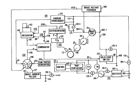
Figure 1 of the present application is similar to
Figure 6 of herein~efore mentioned U.S. Patent No. 4,600,865,
except modified to illustrate the teachings of the
invention. In general, Figure 6 of U.S. Patent No. 4,600,865
has ~een modified to provide:
(a) a brake voltage feedback function 180 which
receives a voltage from ~rake terminals BR(+) and BR(-) and
provides a signal VFB for mixer 146, and
(b) a brake current pulsing function 182 which
receives a signal RS which is at the logic one level when
the associated transportation apparatus 10 is running, and
which is at the logic zero level when transportation
apparatus 10 is not running. For example, signal ~S may be
provided by a normall~ open contact 2R-5 of running relay
2R, a positive source of unidirectional potential, and a
resistor 184. Brake current pulser 182 provides a sguare
wave signal CP to mixer 146 while apparatus 10 is running.
Before describing the added functions in detail,
the reasons for the added functions will first be de-
scribed. Figures 2 and 3 illustrate a brake 64 which may
be used for the brake 64 shown in Figure 1. Figure 2
illustrates brake 64 when it is set or applied, and Figure
3 illustrates brake 64 when it is lifted. Brake 64 in-
cludes a brake magnet assembly 74 which is stationary, and
an armature 76 which is attached to the shaft to be con-
trolled, ie., shaft 66 which drives apparatus 10 from a
suitable electric motor and speed reducer (not shown).
Brake magnet assembly 74 includes a mounting plate 77, a
non-magnetic spacer 81, and a housing 79. Housing 79
includes an electromagnetic brake coil 78, a plurality of
permanent magnets 80, and a friction surface 84. Armature
76 is essentially a magnetic plate member having a flat
surface 86 which, when it contacts surface 84, provides a
~.
i. . -
1~03188
6 53,828
frictional engagement which develops braking torque in
shaft 66. A spring seat 83 is fixed to shaft 66, and a
plurality of springs 82 are disposed to exert a biasing
force on the armature 76 in a direction which tends to
disengage or lift the brake. As shown in Figure 2, in the
absence of current in braXe coil 78~ magnetic flux 85
provided by permanent magnets 80 follows a flux path which
includes housing 79 and armature 76, with the magnetic flux
attracting armature 76 towards surface 84 with an
attractive force which exceeds the oppositely directed
biasing force exerted on the armature 76 by the springs 82.
Thus, in the absence of current in brake coil 78, surface
86 of armature 78 is tightly pressed against surface 84,
and brake 64 is applied or set, providing maximum braking
force. This maximum braking force is illustrated at point
186 in the graph of Figure 4, with Figure 4 plotting force
on the ordinate and brake current Ib on the abcissa. The
substantially V-shaped curve 188 represents the magnetic
force when brake 64 is set or applied, and the substantial-
ly V-shaped curve 190 represents the magnetic force when
brake 64 is lifted.
Initiating current in brake coil 78 produces an
electromagnetic field or flux 87 which opposes the magnetic
flux 85 provided by the permanent magnets 80. Thus, the
flux produced by the brake coil 78 reduces the net flux, it
reduces the attractive force provided by the magnets on
armature 76, and it reduces the braking torque. Increasing
the brake coil current to a value of I2 reduces the magnet-
ic attractive force provided by the resultant flux along
curve 188 until the attractive force is equal to the spring
force at curve point 191. The spring force is illustrated
in Figure 4 by the horizontal broken line 192. A slight
additional increase in the brake coil current then reduces
the attractive force below the spring force, and the
springs 82 start to move the armature 76 away from the
brake magnet assembly 74. This provides an air gap 88
between surfaces 84 and 86 which increases the reluctance
1~0~ 8
7 53,828
of the magnetic path, further reducing the net flux. This
is an unstable condition which results in a quick move of
armature 76 to the maximum air gap 88, resulting in a
vertically downward drop of the attractive force from point
191 on the brake-applied curve 188 to point 193 on the
brake-released curve 190.
Further increases in brake coil current result in
a change in the direction of the flux, but the absolute
value increases as does the net attractive force. If the
brake coil current is increased sufficiently along curve
portion 194 until curve point 195 is reached at current
value I4, the bias spring force is again balanced by the
magnetive attractive force and the armature 76 is attracted
toward the magnet assembly 74. When this occurs, the
reluctance of the magnetic path decreases and causes the
net flux to increase. Thus, the armature gap quickly
closes to apply braking torque again, and the attractive
braking force jumps from point 195 on the brake-released
curve 190 to point 196 on the brake-applied curve 188.
Normally, the brake coil current is not increased to this
high a level, but transient excursions of the brake coil
current can and do occur which may either increase or
decrease the coil current.
Reducing the brake coil current towards zero from
point 196 reduces the magnetic attractive force along curve
portion 197 until it reaches the spring force 192 at point
198 and current value I6. The attractive force then
quickly drops to point 199 on the brake-released curve 190,
as the armature 76 moves away from the brake magnet assem-
bly 74. As the brake coil current continues to reduce, the
magnetic attractive force starts to increase along curve
portion 200 until curve 190 intersects the spring force
curve 192 at point 201 and current value I8, at which time
the attractive force jumps to point 202 on the brake
applied curve 188.
As shown at the top of Figure 4, for an increas-
ing brake coil current, the cross-hatched area 204
138
8 53,828
indicates there is no air gap from zero brake coil current
to current value I2, the open area 206 between current
values I2 and I4 indicates an air gap, and the
cross-hatched area 208 for current values exceeding value
I4 again indicates no air gap.
For a decreasing coil current, the cross-hatched
area 210 indicates no air gap until the brake coil current
value drops to value I6, the open area 212 between current
values I6 and I8 indicate an air gap, and the cross-hatched
area 214 from current value I8 to current zero again
indicates no air gap.
To more clearly indicate the brake coil current
hysteresis involved, the brake coil current Ib is plotted
on the ordinate in Figure 5, versus time on the abcissa.
It will be noted that only a brake coil current in the
relatively narrow range between values I2 and I6 will
result in an air gap regardless of whether the brake coil
current reached that value while increasing or decreasing.
In other words, the brake 64 has first and second overlap-
ping brake current release ranges for increasing anddecreasing values, respectively, of brake coil current,
with the overlapping portions defining a narrow brake
current release window which will cause release of the
brake notwithstanding a momentary brake current excursion
into a brake setting value outside either brake current
release range.
During normal running of the transportation
apparatus 10 it is imperative to always have the brake 64
in the fully released condition. Any rubbing or drag of
the armature 76 on the brake magnet assembly 74 will cause
excessive wear and/or overheating of the brake 64. Com-
plete lifting of the brake 64 can be achieved while appara-
tus 10 is running by controlling the brake coil current to
always be between current values I2 and I6. However, as
the brake temperature changes, so does the value of the
magnetic flux provided by the permanent magnets 80. Thus,
the values of I2 and I6 which will maintain the brake fully
38
9 53,828
released, regardless of the direction of the brake current
when it arrived between values I2 and I6, change with brake
operating temperature, such as illustrated in Figure 6.
Figure 6 illustrates brake current values I2 and I6 and how
they decrease with increasing brake operating temperature
across the operating temperature range of the brake 64. It
will be noted that the ideal brake current is halfway
between current values I2 and I6 regardless of brake
operating temperature. It will also be noted that main-
taining the brake current constant with constant currentregulation causes the brake current to be between values I2
and I6 for only a very short temperature range. Thus, to
maintain the net flux value at the level which will cause
the brake current to be between values I2 and I6, the
running brake current level will have to track the changing
values of I2 and I5. As will be hereinafter described in
detail, this result is achieved by adding a permanent
magnet temperature compensation circuit to the brake
controller of the incorporated patent.
It will be appreciated that the initial adjust-
ment of the temperature compensation circuit is very
critical because the range between current values I2 and I6
is relatively narrow. If the adjustment is incorrect,
brake rubbing can occur. This is illustrated in Figures 7,
8 and 9, which illustrate brake current Ib versus time,
with the current values I2, I4, I6 and I8 being illustrated
with broken horizontal lines. Figure 7 illustrates a
correct adjustment of the brake current Ib. If a positive
going transient at point 216 should cause the brake current
to rise above level I4, brake rubbing will occur at point
218 as the brake current level exceeds I4, and it will
cease at point 220 when the brake current drops below I6.
Brake rubbing is indicated by the heavier portions of the
brake current curves.
In like manner, should a momentary drop in brake
coil current occur at point 222, such as might be caused by
a momentary loss of electrical power, brake rubbing will
1~0~ 8
53,828
occur at point 224 as the brake coil current drops below
value I8, and it will continue until the bra~e current
rises above level I2 at point 226.
Figure 8 illustrates the effect of having the
brake current adjusted such that it normally exceeds level
I6. No brake rubbing will occur until a positive transient
at point 228 drives the brake current above value I4, with
rubbing starting at point 230. Since the brake current
does not fall below the brake release value I6, rubbing
will then continue indefinitely. A negative going tran-
sient from the adjusted level at point 232 in Figure 8 will
not cause prolonged rubbing, as the rubbing will start at
point 234 when the current drops below level I8, and it
will cease at point 236 as the current level passes through
release level I2.
Figure 9 illustrates the effect of having the
brake current adjusted such that it is normally below level
I2, and adjusted to be non-rubbing by first increasing the
value above I6. A positive going transient at point 238
will only cause rubbing from points 240 to 242, while a
negative going transient at 244 will cause indefinite
rubbing, starting at point 246.
The invention effectively widens the brake
current release zone, making the adjustment of the tempera-
ture tracking circuitry much less critical, by pulsing the
brake current during the normal running of the transporta-
tion apparatus 10. The pulsing is uniform, raising and
lowering the coil current by the same magnitude for the
same periods of time, resulting in no change in the average
brake coil current. The magnitude of the pulsing is
selected to be great enough to drive the brake current
through the brake release levels, ie., above I2 when
returning from a negative going transient, and below I6
when returning from a positive going transient. The pulse
amplitude should not be great enough, however, to cause the
operating current to rise above I4 or drop below I8 for any
normal average value of operating current. This solution
~4~ 8
11 53,828
works well for brakes where the magnitude of the range
between I2 and I6 is less than the magnitude of the range
between I6 and I4, and less than the magnitude of the range
between I2 and I8. This has been found to be true for the
brakes tested.
Figures 10, 11 and 12 are similar to Figures 7, 8
and 9, respectively, except illustrating the effects of
adding a pulsing waveform to the operating level of the
brake current. In Figure lO the average brake current
indicated by line 248 is between I2 and I6 and thus the
brake will release following a positive or negative tran-
sient, with or without the square wave pulsing waveform 249
added to the average current waveform. A positive going
transient at 250 initiates brake rubbing at 252 when
current level I4 is reached, which persists only until the
waveform drops to and crosses release level I6 at 254. A
negative going transient at 256 initiates brake rubbing at
258 as the transient crosses level I8, which persists only
until release level I2 is crossed at 260.
Figure 11 illustrates the condition where the
average brake current 262 is above level I6. A positive
going transient at 264 initiates brake rubbing at 266 as
the current passes level I4, and it terminates at 268 as
the lower half cycle of the square wave pulse waveform
drives the current level through the release level I6. A
negative going transient at 270 initiates rubbing at 272 as
the current drops through level 272, and it terminates at
274 as the current rises to and passes through release
level I2.
Figure 12 illustrates the condition where the
average brake current 276 is below release level I2. A
positive going transient at 278 initiates brake rubbing at
280 as the current goes through level I4, with the rubbing
terminating at 282 as the current falls through release
level I6. A negative going transient at 284 initiates
brake rubbing at 286 as the current falls through level I8,
1~0~ 8
12 53,828
and rubbing terminates at 288 as the upper half of the
square wave drives ~he current through release level I2.
Another benefit that is derived from current
pulsing is an improvement in initial brake release. The
first current pulse is oriented such that the upper half
cycle always appears when the brake is to be lifted,
driving the brake current immediately to its maximum value,
ie., above level I6. The current is thus driven more
quickly above level I2 and the brake releases faster and
more positively. With a random pulse initiation, the brake
could drag initially if the first pulse happened to be a
lower half cycle, as the initial current magnitude would be
below release level I2. Without current pulsing, if the
operating current is set below I2, the brake would ~ever
fully lift.
Figure 13 is a block diagram of a servo loop
illustrating how the invention implements temperature
compensation of the permanent magnets 80. Block H1 repre-
sents voltage feedback, and block H2 represents current
feedback. In US. Patent No. 4,500,865 only current feed-
back was used. The voltage feedback Hl is used to cause
the brake current to have the correct temperature charac-
teristic. The ratio of the current and voltage feedback is
set to cause the brake current to track the temperature
dependent change of the permanent magnets. The values of
the current and voltage feedback may be determined by
different techniques, including trial and error. The
following method is a simple, straight forward analytical
one.
In the following equations, the brake resistance
(ohms) increases by Kl (0.393 % per degree C), the resis-
tance temperature coefficient for copper wire. It is
desired to decrease the brake current with increasing brake
temperature by K2, the reduction in magnetic flux from the
permanent magnets 80 with increasing temperature (0.20% per
degree C). The solution chosen uses equations written for
two temperatures in the range of interest, 20 degrees C and
il8
13 53,828
50 degrees C. Solving the equations produced 0.0648 for
Hl, 18.0555 for H2 and 160 for Gl. The results are also
shown in Figure 6, as the "actual Ib". It will be noted
that the "ideal Ib" in Figure 6 is a straight line from
about 274 milliamps at -20 degrees C to about 214 milliamps
at 100 degrees C. The actual brake current, regulated for
zero flux regulation according to the exemplary implementa-
tion cuts through the ideal Ib at points 290 and 292, at 20
degrees C and 50 degrees C, respectively, the calculated
points. For a temperature range of interest of -20 degrees
C to 70 degrees C, the maximum deviation occurs at -20
degrees C and is only about 3.5 ma. This corresponds to a
deviation of about 1.3 %. For comparison, the maximum
deviation using constant current regulation is ab~ut 10.9 %
at 70 degrees C. For constant voltage regulation the
maximum error occurs at -20 degrees C, and is about 9.9 %.
Also, for comparison, the values of I6 and I2 are shown in
Figure 6. It will be noted that the actual Ib for zero
flux regulation stays well between these limits over the
20 temperature range of -20 degrees C to 100 degrees C.
Permanent magnet temperature compensation is therefor
achieved by adding voltage feedback, and changing the value
of current feedback to suit the required compensation
level.
EQUATIONS FOR DETERMINING Hl AND H2
G2 = l/RB (RB = resistance of brake)
GA = Gl/(1 + Gl*Hl)
GB = GA*G2
GC = GB/(l + GB*H2) or (Gl*G2)/(1 + Gl*Hl + Gl*G2*H2) or
30 IB/IR
At Temperature T1:
RBl = RB20*(1 + Kl*(Tl - T20)
IBl = IB20*(1 - K2*(Tl - T20) (desired current)
G2 = G21 = 1/RBl
35 GC = GCl = (Gl*G21)/(1 + Gl*Hl + Gl*G21*H2)
GCl = IBl/IR
14 53,828
At Temperature T2:
RB2 - RB20*(1 + Kl*(T2 - T20)
IB2 = IB20*(1 - K2*(T2 - T20) (desired current)
G2 = G22 = 1/RB2
GC = GC2 = (Gl~G22)/(1 + Gl*Hl + Gl*G22*H2)
GC2 = IB2jI~
From the above, two simultaneous equations may be written
to evaluate H1 and H2:
1) Hl + G21*H2 = G21/GC1 - 1/Gl
2) Hl l G22*H2 ~ G22/GC2 - l/Gl
Rewriting in general terms:
lA) Ml*Hl + Nl*H2 = Ll
2A) M2*Hl + N2*H2 = L2
From which:
Hl = (Ll*N2 - L2*N1)/(Ml*N2 - M2*Nl)
H2 = (Ml*L2 - M2*L1)/(Ml*N2 - M2~Nl)
The values for M1, M2, Nl, N2, Ll and L2 may be obtained
from equations 1 and 2.
The values of ~1 and H2 obtained from the equations force
the brake current to go through the desired current points
at temperatures Tl and T2. The changes in brake coil
resistance and permanent magnet flux are compensated at T1
and T2.
Figure 14 is a detailed schematic diagram which
illustrates how Figure 7 of U.S. Patent 4,600,865, may be
modified according to the teachings of the invention, to
incorporate both temperature compensation for the permanent
magnets ~0 in the brake 64 and the square wave addition to
the running brake current waveform. The voltage feedback
function 180 is provided by an operational amplifier 300
connected as a conventional differential amplifier. The
differential amplifier monitors the voltage across the
brake coil 78 and provides a feedback signal VEB. The
current feedback IA is adjusted to provide the calculated
ratio of current to voltage feedback by proper selection of
the value of resistor 301. Resistor 301 is shown as being
rA
1~-0~ 38
53,828
adjustable, but its value may be calculated and a fix~d
resistor used to prevent accidental misadjustment.
The square wave pulsing function 182 is provided
by operational amplifiers 302 and 304 connected as an
astable multivibrator. The output, which is ~aken from
operational amplifier 302, is a square wave having a
magnitude of about +/- 14 volts and a frequency of about
2/3 Hz. Two solid state switches 306 and 308 are used to
control the current pulsing function, such as AD7510DI.
The control involves properly orienting the initial pulse
to insure maximum brake current when the brake is to be
initially lifted, and the termination of the pulsing when a
controlled stop is initiated.
More specifically, solid state switches 306 and
308, which are normally closed and normally open, respec-
tively, are controlled by the condition of running relay 2R
shown in Figure 1. When the transportation apparatus 10 is
not being driven by its drive motor, such as at the start
of a controlled stop, running relay 2R is dropped out, its
contact 2R-S is open, and normally open switch 308 is open,
disconnecting the current pulsing waveform CP from junction
310 and mixer 146. Thus, there is no current pulsing from
function 182 during the controlled deceleration interval.
When the transportation apparatus is not running,
the normally closed switch 306 connects a source of posi-
tive unidirectional potential to the astable multivibrator
to maintain feedback capacitor 312 of operational amplifier
304 charged to about -14 volts. When transportation
apparatus 10 is started, the run contactor 120 energizes
relay 2R, contact 2R-5 closes, switch 306 opens and switch
308 closes. Operational amplifier 302 changes state, and
the negative portion of the initial pulse is applied to
mixer 146 which inverts this to cause the brake current to
rise to its highest value on release of the brake. The
change in state of operational amplifier 302 causes capaci-
tor 312 to begin charging towards the opposite polarity.
At about +5 volts it changes the state of operational
i;~O~ 8
16 53,828
amplifier 3~2, which functions as a Schmitt trigger The
circuit then continues to periodically change state to
generate the desired square waveform pulses.
In summary, the present invention improves the
operation of transportation apparatus, such as escalators,
which have one or more brakes which are controlled to
provide a controlled stop. The present invention does not
relate to the controlled stop function per se, but to the
operation of the brake, or brakes, while the transportation
apparatus is running, before the initiation of a controlled
stop. The invention adds brake voltage feedback to the
brake current feedback of U.S. Patent 4,600,865, with the
value of current feedback being selected to provide a ratio
of current to voltage feedback which causes the running
brake current to closely track the temperature characteris-
tic of the permanent magnets used in the controlled brake.
Thus, the desired flux cancellation is maintained over the
operating temperature range of the brake. The criticality
in the setting of the brake current feedback is greatly
alleviated by another aspect of the invention in which a
pulsing waveform is added to the running brake current.
Thus, the average brake current may be above or below the
desired narrow range and the added waveform will still
drive the current into th~ brake release range, to prevent
a transient in the brake current from initiating brake
dragging for an indefinite period of time. The first pulse
is additionally controlled such that the brake current is
driven to its maximum value when the brake is lifted to
initiate running of the transportation apparatus, to insure
a fast, clean brake release with minimal dragging.