Language selection

Search

Patent 1303640 Summary

Third-party information liability

Some of the information on this Web page has been provided by external sources. The Government of Canada is not responsible for the accuracy, reliability or currency of the information supplied by external sources. Users wishing to rely upon this information should consult directly with the source of the information. Content provided by external sources is not subject to official languages, privacy and accessibility requirements.

Claims and Abstract availability

Any discrepancies in the text and image of the Claims and Abstract are due to differing posting times. Text of the Claims and Abstract are posted:

  • At the time the application is open to public inspection;
  • At the time of issue of the patent (grant).
(12) Patent: (11) CA 1303640
(21) Application Number: 1303640
(54) English Title: FOLD AND ROLL STAGING
(54) French Title: SCENE REPLIABLE MOBILE SUR ROULETTES
Status: Expired and beyond the Period of Reversal
Bibliographic Data
(51) International Patent Classification (IPC):
  • A63J 01/00 (2006.01)
  • A47B 25/00 (2006.01)
  • E04H 03/24 (2006.01)
  • E04H 03/28 (2006.01)
(72) Inventors :
  • STATEN, KENNETH EDWARD (United States of America)
  • ROGERS, ORLEY DAVID (United States of America)
(73) Owners :
  • STAGERIGHT CORPORATION
(71) Applicants :
  • STAGERIGHT CORPORATION (United States of America)
(74) Agent: MARKS & CLERK
(74) Associate agent:
(45) Issued: 1992-06-16
(22) Filed Date: 1988-07-06
Availability of licence: N/A
Dedicated to the Public: N/A
(25) Language of filing: English

Patent Cooperation Treaty (PCT): No

(30) Application Priority Data:
Application No. Country/Territory Date
80,301 (United States of America) 1987-07-31

Abstracts

English Abstract


ABSTRACT OF THE DISCLOSURE
A portable and foldable platform stage assembly has
two support panels movable from a collapsed position with panels
closely adjacent each other to an operative position with the
panels in a single plane, the inner edges in substantial contact.
Roller wheels move from a storage position when the panels are
in operative position to a floor contacting position when the
panels are collapsed for storage or movement. Outer legs move
from a storage position to a vertical operative position when
the panels are shifted to operative position. A central support
frame pivotally supports the inner edges of the platform panels
in the two positions with shaped spaced support links which
provide positive support in the operative position and adapt to
a receiving position when the panels are moved to storage
positions.


Claims

Note: Claims are shown in the official language in which they were submitted.

THE EMBODIMENTS OF THE INVENTION IN WHICH AN EXCLUSIVE PROPERTY OR
PRIVILEGE IS CLAIMED ARE DEFINED AS FOLLOWS:
1.
A fold and roll platform assembly comprising:
(a) a pair of platform panels,
(b) outer legs on each said panels to support the
outer edges in operative position,
(c) a central support frame to support the panels
in storage position when said panels are disposed parallel to
each other or in operative position when positioned inner edge
to inner edge in a common plane, said support frame comprising:
(1) a base member on said frame extending in
the same direction and spaced from said
common plane,
(2) main support legs at each end of said frame
extending upwardly and pivotally connected
to said respective panels adjacent the
respective inner edges of said panels, and
pivotally connected to said base member,
(3) secondary support legs spaced from said
main support legs each pivotally connected
to said respective panels and said base
member,
said main and secondary support legs being
simultaneously movable to allow said panels to shift from a
vertical upright storage position to a horizontal operative
position, said main and secondary support legs acting in
substantially parallel position to support the inner edges of
said panels on said base member of said frame.
- 6 -

2.
A fold and roll platform assembly as defined in claim 1
in which operative links respectively connect said outer legs
with said main support legs to move said outer legs from a
storage position adjacent a panel to an operative position
perpendicular to a panel when said panels are moved from a
storage position to an operative position.
3.
A fold and roll platform assembly as defined in claim 2
in which roller wheels are mounted on extensions of said
respective operative links to shift from a surface contacting
position to a storage position when said panels are moved on
said frame from a storage position to an operative position.
4.
A fold and roll platform assembly as defined in claim 1
in which said secondary legs are formed in a dogleg shape to
provide a concave clearance area for the inner edge of a panel
as it moves to a storage position.
5.
A fold and roll platform assembly as defined in claim 1
in which each said main support leg has a bend to provide a
storage space for one end of each said secondary support leg
when said panels are in storage position.
-7-

6.
A fold and roll platform assembly as defined in claim 1
in which a short arm is positioned and secured adjacent the
inner edge of each said platform panel, and the upper ends of
said main support legs and said secondary support legs are
pivotally attached to said arm at spaced positions.
7.
A fold and roll platform assembly as defined in claim 6
in which each said main support leg has a bend to provide a
storage space for said short arm and one end of said secondary
leg when said panels are in storage position.
- 8 -

Description

Note: Descriptions are shown in the official language in which they were submitted.


1~036~a0
Title
FOLD AND RO$L STAGI~G
Field of Invention
Portable equipment for forming stage platforms for
musical and dramatic presentations.
Bac~around and Features of the Invention
Many educational and religious organizations cannot
provide permanent stage platforms in tbe physical facilities
available. When visiting choruses or dramatic groups are invited
for a performance, it is possible to rent staging eguipment for
a temporary set-up after which the equipment is dismantled and
returned. In addition, when visiting musical stars come into
auditoriums, stadiums, or arenas, frequently it is necessary
to set up an extensive stage area not normally available.
To meet these needs, it is desirable to have staging
equipment which can be easily stored and transported. It is
also preferable to have equipment which can be folded into
compact units to save space for storage and trucking. It is
also desirable to have stage units which can be readily handled
by one, or, at most, two persons so that large set-up crews are
not needed.
, *
~' ^'

i~036~0
It i3 an ob~ect of the present invention to provide
a foldable staging unit which is easily moved around by one
person, which can be stored in a compact form and readily
transported, and which can be easily qet up to provide a solid
stable unit which meets all the requirements of safety when
used for holding qroups of people, musical instruments, and the
like.
Other objects and features of the invention will be
set forth in the following description and claims in which the
principles of the invention are set forth together with details
to enable persons skilled in the art to practice the invention,
all in connection with the best mode presently contemplated for
the invention.
Brief DescriDtion of the Dravinqs
DRA~INGS accompany the disclosure and the various
views thereof may be briefly described as:
FIG. 1, an elevation view of a folded stage unit.
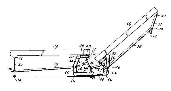
FIG. 2, an elevation view of a stage unit with one
section open.
FIG. 3, an elevation view similar to FIG. 2 with one
section open and a second section in a transition position.
FIG. ~, a stage unit entirely opened to operative
position.
FIG. 5, an enlarged view of the central support system
for the unit in a fully open position.
-2-
`

1~03~
Detailed Description of the Invention
and the Mbnner and Proces6 of ~-~nq It
In FIG. 1, a folded stage unit 1s illustrated with
two platform panel elements 20 and 22 connected by a special
hinging system which positions two rollers at the base to
facilitate moving the folded unit to and from storage or trucking
facilities. In FIG. 2, the platform element 20 is still in
upright position while element 22 is lowered to an operative
position. Each unit has similar support systems on each side
; of the platform elements and only one side will be described
in detail. The panel elements 20, 22 are constructed in a
conventional manner of plywood, or honeycomb reinforced panels
of suitable load bearing quality.
` Outer legs 30 are hinged at 32 to the bottom outer end
; of the platform elements and each has an end 34 to contact the
support floor. These ends 34 may be suitably padded and may
be extensible if different heights are desired.
',
~' Each outer leg 30 is pivotally connected at 36 to an
operating and stabilizing link 38 which at an inner end is
connected pivotally at 40 to a central support frame having
vertical main support leg elements 44 pivotally connected at
the bottom ends at 46 to a cross brace member 4B. The leg
elements are bent inwardly at the pivot point 40. At the top end
of the legs 44 a short arm 50 is pivotally connected at 52.
This arm is positioned horizontally below the inner edge of the
platform element 22 as shown in FIG. 2 when the platform element
is in operative position. A plate 60 secures the arm 50 to the
i bottom surface of the platform elements 20 and 22 adjacent the inner edges.
3-
:

13036'~0
Each llnk 38 has a b~furcato bracket exten~ion 62
wh~ch mounts a roller wheel 6~ on a short axle 66. As illustrated
in FIG. 2, the wheel 62 in the open side below platform element
22 is spaced away from the support plane 68. On the right ~ide
in conjunction in the upriqht element 20 the roller 64 is in
contact with the support plane.
Reverting to the central support frame, the legs 44
and the cross brace members 48 are pivotally secured together,
and suitable lateral members extend transversely of the platform
elements to rigidly connect the opposed frames and outer leg~
on each side of the platform elements. The cross brace member
48 has a short vertical upright post 70. Dogleg struts or links
~ 1
-172 are pivoted at the short end at 74 to the inner end of arm 50
and at the long end at 76 to the upright post 70.
,;
. .~,1
IlIn FIG. 3, the parts are shown with platform element
. .
22 in open position and element 20 moved from the storage
position to a 45 position to illustrate how the moving support
partQ function. FIG. 4 illustrates the fully operative position
with both platform panels horizontally positioned with the inner
edges close together. FIG. 5 shows the central support frame in
a larger ~ize, again in fully open position.
It will be appreciated that in the opening or closing
movement, the links 38 will act on the outer legs to move them
respectively to the vertical support position or ta the folded
,. . .,
position shown in FIG. 1. Also, in FIG. 1 and at the right side
of FIG. 2, the importance of the shape of legs 44 and dogleg
llnks 72 i# evident. The inner edges of the panels 20, 22 drop
1 into the recess formed by the dogleg links 72, and the bend-in
~ 4-
.. '''~ ~

legs 44 permlts the nestling of the arms 50 and cros~ member
assoclated wlth the spaced frames. In the storage posltion,
the roller wheels 64 contact the support surface to permit easy
movement of the collapsed assembly to and from the selected
site. In the operative position, the wheels 62 are in a non-
functioning storage positlon.
In the operative position of the panels ~FIGS. 4 and
5~, they are supported centrally by the legs 44 and links 72,
each in turn supported in substantially parallel position on
the frame base 48 with the short vertical post 70 supporting
the lower end of link 72. In the folded position shown at the
right side of FIG. 2, the panels are supported mainly by legs 44.
If vertical extensions are desired to raise the level
of the entire unit, retractible extensions can readily be
installed at 34 on legs 30 and to the base end of legs 44.
The swinging mount on the two platform panels has a
., .
significant function in the operation of the assembly. In
essence, there is a parallelogram mount with the main leg 44
and the secondary leg 72 operating simultaneously. The secondary
leg is shorter than the main leg. With this system, when a
platform panel is lifted in the initial movement to move it to
a storage position, it actually moves lineally away from the
other panel 80 there is ample clearance to avoid interference
of tbe inner edges of the panels as the panel is lifted. At the
end of the upward stroke, the æhape of the legs 44 and 72
..
~ function as described to allow the panel edge to move into the
, 1 .
lowered storage poæition. The leg 44 starts in a substantially
vertical position in storage position and ends in the same
. , ~
position when in platform position. This makes it possible to
provide a lock on this main leg in either position.
,' ~ ~`'
`', ~ ~, . '
~ , .

Representative Drawing
A single figure which represents the drawing illustrating the invention.
Administrative Status

2024-08-01:As part of the Next Generation Patents (NGP) transition, the Canadian Patents Database (CPD) now contains a more detailed Event History, which replicates the Event Log of our new back-office solution.

Please note that "Inactive:" events refers to events no longer in use in our new back-office solution.

For a clearer understanding of the status of the application/patent presented on this page, the site Disclaimer , as well as the definitions for Patent , Event History , Maintenance Fee  and Payment History  should be consulted.

Event History

Description Date
Time Limit for Reversal Expired 2008-06-16
Letter Sent 2007-06-18
Inactive: IPC from MCD 2006-03-11
Grant by Issuance 1992-06-16

Abandonment History

There is no abandonment history.

Owners on Record

Note: Records showing the ownership history in alphabetical order.

Current Owners on Record
STAGERIGHT CORPORATION
Past Owners on Record
KENNETH EDWARD STATEN
ORLEY DAVID ROGERS
Past Owners that do not appear in the "Owners on Record" listing will appear in other documentation within the application.
Documents

To view selected files, please enter reCAPTCHA code :


To view images, click a link in the Document Description column. To download the documents, select one or more checkboxes in the first column and then click the "Download Selected in PDF format (Zip Archive)" or the "Download Selected as Single PDF" button.

List of published and non-published patent-specific documents on the CPD .

If you have any difficulty accessing content, you can call the Client Service Centre at 1-866-997-1936 or send them an e-mail at CIPO Client Service Centre.


Document
Description 
Date
(yyyy-mm-dd) 
Number of pages   Size of Image (KB) 
Claims 1993-10-31 3 79
Abstract 1993-10-31 1 22
Drawings 1993-10-31 3 62
Descriptions 1993-10-31 5 175
Representative drawing 2000-08-06 1 12
Maintenance Fee Notice 2007-07-29 1 172
Maintenance fee payment 1996-05-15 1 34
Maintenance fee payment 1995-05-10 1 33
Maintenance fee payment 1994-05-15 1 29