Sélection de la langue

Search

Sommaire du brevet 1303640 

Énoncé de désistement de responsabilité concernant l'information provenant de tiers

Une partie des informations de ce site Web a été fournie par des sources externes. Le gouvernement du Canada n'assume aucune responsabilité concernant la précision, l'actualité ou la fiabilité des informations fournies par les sources externes. Les utilisateurs qui désirent employer cette information devraient consulter directement la source des informations. Le contenu fourni par les sources externes n'est pas assujetti aux exigences sur les langues officielles, la protection des renseignements personnels et l'accessibilité.

Disponibilité de l'Abrégé et des Revendications

L'apparition de différences dans le texte et l'image des Revendications et de l'Abrégé dépend du moment auquel le document est publié. Les textes des Revendications et de l'Abrégé sont affichés :

  • lorsque la demande peut être examinée par le public;
  • lorsque le brevet est émis (délivrance).
(12) Brevet: (11) CA 1303640
(21) Numéro de la demande: 1303640
(54) Titre français: SCENE REPLIABLE MOBILE SUR ROULETTES
(54) Titre anglais: FOLD AND ROLL STAGING
Statut: Périmé et au-delà du délai pour l’annulation
Données bibliographiques
(51) Classification internationale des brevets (CIB):
  • A63J 01/00 (2006.01)
  • A47B 25/00 (2006.01)
  • E04H 03/24 (2006.01)
  • E04H 03/28 (2006.01)
(72) Inventeurs :
  • STATEN, KENNETH EDWARD (Etats-Unis d'Amérique)
  • ROGERS, ORLEY DAVID (Etats-Unis d'Amérique)
(73) Titulaires :
  • STAGERIGHT CORPORATION
(71) Demandeurs :
  • STAGERIGHT CORPORATION (Etats-Unis d'Amérique)
(74) Agent: MARKS & CLERK
(74) Co-agent:
(45) Délivré: 1992-06-16
(22) Date de dépôt: 1988-07-06
Licence disponible: S.O.
Cédé au domaine public: S.O.
(25) Langue des documents déposés: Anglais

Traité de coopération en matière de brevets (PCT): Non

(30) Données de priorité de la demande:
Numéro de la demande Pays / territoire Date
80,301 (Etats-Unis d'Amérique) 1987-07-31

Abrégés

Abrégé anglais


ABSTRACT OF THE DISCLOSURE
A portable and foldable platform stage assembly has
two support panels movable from a collapsed position with panels
closely adjacent each other to an operative position with the
panels in a single plane, the inner edges in substantial contact.
Roller wheels move from a storage position when the panels are
in operative position to a floor contacting position when the
panels are collapsed for storage or movement. Outer legs move
from a storage position to a vertical operative position when
the panels are shifted to operative position. A central support
frame pivotally supports the inner edges of the platform panels
in the two positions with shaped spaced support links which
provide positive support in the operative position and adapt to
a receiving position when the panels are moved to storage
positions.

Revendications

Note : Les revendications sont présentées dans la langue officielle dans laquelle elles ont été soumises.


THE EMBODIMENTS OF THE INVENTION IN WHICH AN EXCLUSIVE PROPERTY OR
PRIVILEGE IS CLAIMED ARE DEFINED AS FOLLOWS:
1.
A fold and roll platform assembly comprising:
(a) a pair of platform panels,
(b) outer legs on each said panels to support the
outer edges in operative position,
(c) a central support frame to support the panels
in storage position when said panels are disposed parallel to
each other or in operative position when positioned inner edge
to inner edge in a common plane, said support frame comprising:
(1) a base member on said frame extending in
the same direction and spaced from said
common plane,
(2) main support legs at each end of said frame
extending upwardly and pivotally connected
to said respective panels adjacent the
respective inner edges of said panels, and
pivotally connected to said base member,
(3) secondary support legs spaced from said
main support legs each pivotally connected
to said respective panels and said base
member,
said main and secondary support legs being
simultaneously movable to allow said panels to shift from a
vertical upright storage position to a horizontal operative
position, said main and secondary support legs acting in
substantially parallel position to support the inner edges of
said panels on said base member of said frame.
- 6 -

2.
A fold and roll platform assembly as defined in claim 1
in which operative links respectively connect said outer legs
with said main support legs to move said outer legs from a
storage position adjacent a panel to an operative position
perpendicular to a panel when said panels are moved from a
storage position to an operative position.
3.
A fold and roll platform assembly as defined in claim 2
in which roller wheels are mounted on extensions of said
respective operative links to shift from a surface contacting
position to a storage position when said panels are moved on
said frame from a storage position to an operative position.
4.
A fold and roll platform assembly as defined in claim 1
in which said secondary legs are formed in a dogleg shape to
provide a concave clearance area for the inner edge of a panel
as it moves to a storage position.
5.
A fold and roll platform assembly as defined in claim 1
in which each said main support leg has a bend to provide a
storage space for one end of each said secondary support leg
when said panels are in storage position.
-7-

6.
A fold and roll platform assembly as defined in claim 1
in which a short arm is positioned and secured adjacent the
inner edge of each said platform panel, and the upper ends of
said main support legs and said secondary support legs are
pivotally attached to said arm at spaced positions.
7.
A fold and roll platform assembly as defined in claim 6
in which each said main support leg has a bend to provide a
storage space for said short arm and one end of said secondary
leg when said panels are in storage position.
- 8 -

Description

Note : Les descriptions sont présentées dans la langue officielle dans laquelle elles ont été soumises.

1~036~a0
Title
FOLD AND RO$L STAGI~G
Field of Invention
Portable equipment for forming stage platforms for
musical and dramatic presentations.
Bac~around and Features of the Invention
Many educational and religious organizations cannot
provide permanent stage platforms in tbe physical facilities
available. When visiting choruses or dramatic groups are invited
for a performance, it is possible to rent staging eguipment for
a temporary set-up after which the equipment is dismantled and
returned. In addition, when visiting musical stars come into
auditoriums, stadiums, or arenas, frequently it is necessary
to set up an extensive stage area not normally available.
To meet these needs, it is desirable to have staging
equipment which can be easily stored and transported. It is
also preferable to have equipment which can be folded into
compact units to save space for storage and trucking. It is
also desirable to have stage units which can be readily handled
by one, or, at most, two persons so that large set-up crews are
not needed.
, *
~' ^'

i~036~0
It i3 an ob~ect of the present invention to provide
a foldable staging unit which is easily moved around by one
person, which can be stored in a compact form and readily
transported, and which can be easily qet up to provide a solid
stable unit which meets all the requirements of safety when
used for holding qroups of people, musical instruments, and the
like.
Other objects and features of the invention will be
set forth in the following description and claims in which the
principles of the invention are set forth together with details
to enable persons skilled in the art to practice the invention,
all in connection with the best mode presently contemplated for
the invention.
Brief DescriDtion of the Dravinqs
DRA~INGS accompany the disclosure and the various
views thereof may be briefly described as:
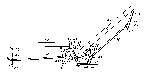
FIG. 1, an elevation view of a folded stage unit.
FIG. 2, an elevation view of a stage unit with one
section open.
FIG. 3, an elevation view similar to FIG. 2 with one
section open and a second section in a transition position.
FIG. ~, a stage unit entirely opened to operative
position.
FIG. 5, an enlarged view of the central support system
for the unit in a fully open position.
-2-
`

1~03~
Detailed Description of the Invention
and the Mbnner and Proces6 of ~-~nq It
In FIG. 1, a folded stage unit 1s illustrated with
two platform panel elements 20 and 22 connected by a special
hinging system which positions two rollers at the base to
facilitate moving the folded unit to and from storage or trucking
facilities. In FIG. 2, the platform element 20 is still in
upright position while element 22 is lowered to an operative
position. Each unit has similar support systems on each side
; of the platform elements and only one side will be described
in detail. The panel elements 20, 22 are constructed in a
conventional manner of plywood, or honeycomb reinforced panels
of suitable load bearing quality.
` Outer legs 30 are hinged at 32 to the bottom outer end
; of the platform elements and each has an end 34 to contact the
support floor. These ends 34 may be suitably padded and may
be extensible if different heights are desired.
',
~' Each outer leg 30 is pivotally connected at 36 to an
operating and stabilizing link 38 which at an inner end is
connected pivotally at 40 to a central support frame having
vertical main support leg elements 44 pivotally connected at
the bottom ends at 46 to a cross brace member 4B. The leg
elements are bent inwardly at the pivot point 40. At the top end
of the legs 44 a short arm 50 is pivotally connected at 52.
This arm is positioned horizontally below the inner edge of the
platform element 22 as shown in FIG. 2 when the platform element
is in operative position. A plate 60 secures the arm 50 to the
i bottom surface of the platform elements 20 and 22 adjacent the inner edges.
3-
:

13036'~0
Each llnk 38 has a b~furcato bracket exten~ion 62
wh~ch mounts a roller wheel 6~ on a short axle 66. As illustrated
in FIG. 2, the wheel 62 in the open side below platform element
22 is spaced away from the support plane 68. On the right ~ide
in conjunction in the upriqht element 20 the roller 64 is in
contact with the support plane.
Reverting to the central support frame, the legs 44
and the cross brace members 48 are pivotally secured together,
and suitable lateral members extend transversely of the platform
elements to rigidly connect the opposed frames and outer leg~
on each side of the platform elements. The cross brace member
48 has a short vertical upright post 70. Dogleg struts or links
~ 1
-172 are pivoted at the short end at 74 to the inner end of arm 50
and at the long end at 76 to the upright post 70.
,;
. .~,1
IlIn FIG. 3, the parts are shown with platform element
. .
22 in open position and element 20 moved from the storage
position to a 45 position to illustrate how the moving support
partQ function. FIG. 4 illustrates the fully operative position
with both platform panels horizontally positioned with the inner
edges close together. FIG. 5 shows the central support frame in
a larger ~ize, again in fully open position.
It will be appreciated that in the opening or closing
movement, the links 38 will act on the outer legs to move them
respectively to the vertical support position or ta the folded
,. . .,
position shown in FIG. 1. Also, in FIG. 1 and at the right side
of FIG. 2, the importance of the shape of legs 44 and dogleg
llnks 72 i# evident. The inner edges of the panels 20, 22 drop
1 into the recess formed by the dogleg links 72, and the bend-in
~ 4-
.. '''~ ~

legs 44 permlts the nestling of the arms 50 and cros~ member
assoclated wlth the spaced frames. In the storage posltion,
the roller wheels 64 contact the support surface to permit easy
movement of the collapsed assembly to and from the selected
site. In the operative position, the wheels 62 are in a non-
functioning storage positlon.
In the operative position of the panels ~FIGS. 4 and
5~, they are supported centrally by the legs 44 and links 72,
each in turn supported in substantially parallel position on
the frame base 48 with the short vertical post 70 supporting
the lower end of link 72. In the folded position shown at the
right side of FIG. 2, the panels are supported mainly by legs 44.
If vertical extensions are desired to raise the level
of the entire unit, retractible extensions can readily be
installed at 34 on legs 30 and to the base end of legs 44.
The swinging mount on the two platform panels has a
., .
significant function in the operation of the assembly. In
essence, there is a parallelogram mount with the main leg 44
and the secondary leg 72 operating simultaneously. The secondary
leg is shorter than the main leg. With this system, when a
platform panel is lifted in the initial movement to move it to
a storage position, it actually moves lineally away from the
other panel 80 there is ample clearance to avoid interference
of tbe inner edges of the panels as the panel is lifted. At the
end of the upward stroke, the æhape of the legs 44 and 72
..
~ function as described to allow the panel edge to move into the
, 1 .
lowered storage poæition. The leg 44 starts in a substantially
vertical position in storage position and ends in the same
. , ~
position when in platform position. This makes it possible to
provide a lock on this main leg in either position.
,' ~ ~`'
`', ~ ~, . '
~ , .

Dessin représentatif
Une figure unique qui représente un dessin illustrant l'invention.
États administratifs

2024-08-01 : Dans le cadre de la transition vers les Brevets de nouvelle génération (BNG), la base de données sur les brevets canadiens (BDBC) contient désormais un Historique d'événement plus détaillé, qui reproduit le Journal des événements de notre nouvelle solution interne.

Veuillez noter que les événements débutant par « Inactive : » se réfèrent à des événements qui ne sont plus utilisés dans notre nouvelle solution interne.

Pour une meilleure compréhension de l'état de la demande ou brevet qui figure sur cette page, la rubrique Mise en garde , et les descriptions de Brevet , Historique d'événement , Taxes périodiques et Historique des paiements devraient être consultées.

Historique d'événement

Description Date
Le délai pour l'annulation est expiré 2008-06-16
Lettre envoyée 2007-06-18
Inactive : CIB de MCD 2006-03-11
Accordé par délivrance 1992-06-16

Historique d'abandonnement

Il n'y a pas d'historique d'abandonnement

Titulaires au dossier

Les titulaires actuels et antérieures au dossier sont affichés en ordre alphabétique.

Titulaires actuels au dossier
STAGERIGHT CORPORATION
Titulaires antérieures au dossier
KENNETH EDWARD STATEN
ORLEY DAVID ROGERS
Les propriétaires antérieurs qui ne figurent pas dans la liste des « Propriétaires au dossier » apparaîtront dans d'autres documents au dossier.
Documents

Pour visionner les fichiers sélectionnés, entrer le code reCAPTCHA :


Pour visualiser une image, cliquer sur un lien dans la colonne description du document. Pour télécharger l'image (les images), cliquer l'une ou plusieurs cases à cocher dans la première colonne et ensuite cliquer sur le bouton "Télécharger sélection en format PDF (archive Zip)" ou le bouton "Télécharger sélection (en un fichier PDF fusionné)".

Liste des documents de brevet publiés et non publiés sur la BDBC .

Si vous avez des difficultés à accéder au contenu, veuillez communiquer avec le Centre de services à la clientèle au 1-866-997-1936, ou envoyer un courriel au Centre de service à la clientèle de l'OPIC.


Description du
Document 
Date
(aaaa-mm-jj) 
Nombre de pages   Taille de l'image (Ko) 
Revendications 1993-10-31 3 79
Abrégé 1993-10-31 1 22
Dessins 1993-10-31 3 62
Description 1993-10-31 5 175
Dessin représentatif 2000-08-06 1 12
Avis concernant la taxe de maintien 2007-07-29 1 172
Paiement de taxe périodique 1996-05-15 1 34
Paiement de taxe périodique 1995-05-10 1 33
Paiement de taxe périodique 1994-05-15 1 29