Note: Descriptions are shown in the official language in which they were submitted.
3675-0l0-00l
~3~7
REMOTE TEACHING SYSTEM
Technical Field
Th~ present invention concerns a system which
permits a teacher to instruct a number of students in which
the students and the teacher are dispersed among remote
sites.
' 10 Backqround Art
Instruction by a teacher of students assembled in a
classroom is an effective method of teaching, since a student
in a classroom can ask questions of the teacher and receive
an immediate answer to clarify points of the lesson being
taught which the student does not understand. In addition,
the teacher can pose questions to students in the classroom
and receive immediate replies to maintain the attentiveness
of the students and to verify that the students are
comprehending the lesson being taught.
However, it is often necessary to teach students
who cannot be brought together in a ~lassroom with a teacher.
For example, it may be necessary to teach students who are
hospitalized or who for some other reason cannot attend a
classroom lecture. It may also be desired to provide
instruction in a continuing-education program or employee-
training program to persons no longer in schosl who live or
work at widely dispersed sites and for whom it would be
impractical to bring together in a classroom for instruction.
!
2--
~3~3~
Various schemes involving televised or video taped
lectures have been tried for teaching students at sites
remote from a teacher. However, no altogether satisfactory
method has heretofore been available for teaching students
located at sites remote from each other and the teacher.
One approach for teaching students in remote sites
involves providing a direct television :Link between each
student site and the teacher in paralle:L with a telephone
link between the student sites and the teacher. In this way
the lecture of the teacher can ~e transmitted "live" to each
of the students and the students can ask questions of the
teacher over the telephone link. However, a direct
television link to a remote site is extremely expensive and
consequently live broadcasts of a lecture with provision for
student response by telephone is generally impractical for
economic reasons, particularly when more than a few student
sites are involved.
An article by D. Scott published in the February
1982 issue of Popular Science discloses a microprocessor-
~ased audio-visual teaching system for linking students at
widely scattered study centers and a teacher at a university.
Terminal equipment for each study center consists of a
microprocessor unit, a television set, two telephone lines
and a stereo cassette recorder. Prerecorded lessons can be
played on the stereo cassette recorder. One of the telephone
lines is for audio communications and the other telephone
line is for communicating visual information. The teaching
system of the Scott article provides for talk-back and
write-back from every terminal. Write-back is accomplished
by means of a light pen. The system uses internal programs
that can be taped, transmitted live or a mixture of the two.
A teacher can make his or her own taped lessons by rec~rding
illustrative material with a television ca~era, making
~a3~31~7
drawings on a graphics tablet, or entering typed information
on a keyboard. The picture elements thus entered can be
arranged and scaled on a video monitor to suit the teacher
and then transferred to a stereo cassette tape. According to
the article, the tape can be used by inclividual machines or
sent over phone lines.
The audio-visual teaching syst:em disclosed in the
Scott article has a number of significarlt drawbacks. For
example, conventional stereo cassette tapes have limited data
~torage capacity so that only a relatively limited set of
images can be stored on the tape.
Disclosure of Invention
I have invented a remote teaching system which
permits a teacher to instruct a plurality of students at
widely separated remote sites and which avoids problems o~`
the prior art noted above.
Broadly, the remote teaching system of the
invention includes a teacher station and a plurality of
student stations. The teacher station and the student
stations may be located at remote ~ites which are
interconnected by a telephone system.
Each station includes a voice telephone set which
is connectable to the telephone system for voice
communication among the various stations. ~ach station also
includes a video display monitor such as a television set for
displaying visual images. Each station also includes a video
media player connected to the video display monitor for
playing video media such as a video recorded lecture by a
teacher to produce visual images on the display monitor. The
video media player has a start/stop-control-signal input port
X
~3~
and is adapted to start and stop the playing of video media
in response to start/stop control signals applied to the
start/stop-control signal input port.
Each student station of the remote teaching system
of the invention includes a video-media-playPr controller
which is connected to the start/stop-control-signal input
port o~ the video media player. The video msdia-player
controller is connectable to the telephone system for
receiving telephonic start/stop control signals ov~r the
telephone system. The video-media-player controller is
adapted to transmit start/stop control signals to the
start/stop-control-~ignal input port of the video media
player in response to receipt of telephonic start/stop
control signals to controllably start and stop the playing of
video media in the video media player.
The teacher station of the remote teaching system
of the invention includes a video-media-player master
controller which i5 connected to the start/stop-control-
signal input port of the video media player of the teacherstation. The video-media-player master controller is
connectable to the telephone system for transmitting
telephonic start/stop control signals over the telephone
system. The video-media-player master controller is adapted
to generate start/stop control signals in response to
instructions from an operator of the master controller and to
apply the signals to the start/stop-control-signal input port
of the video media player o~ the teacher station. The
video-media-player master controller is ~urther adapted to
transmit corresponding telephonic start/stop control signals
over the telephone system to the video-media-player
controllers of the student stations, so that playing of the
~'e~
~'.1"
~.3~3~
video media player of the teacher station and the video media
players of the student stations can be started and stopped
substantially in synchronism.
Preferably, the video-media-p]ayer master
controller includes a digital computer and a modem. The
digital computer has random-access memory for storing data
and programs, a central processing unit in communication with
the random-access memory for accessing programs stored in the
memory, a keyboard in communication Wit~l the random-access
memory for entering data and programs into the memory, and an
input/output channel. Th digital computer preferably also
includes a removable-media mass storage device such as a
~loppy magnetic disk storage unit for data and program entry
and storage. The modem is connected to the input/output
channel of the digital computer for receiving start/stop-
control-signal communication commands from the computer. The
modem is connectable to the telephone system for transmitting
the telephonic start/stop control signals over the telephone
system in response to the start/stop~control-signal
communication co~mands. The input/output channel of the
digital computer is also ccnnected to the start/stop-
control-signal input port of the video-media player of the
teacher station for transmitting start/stop control signals
to the video media player.
The video-media-player controller of each student
station preferably comprises a digital computer and a modem.
The digital computer has a random-access memory, a central
processing unit, a keyboard, and an input/output channel as
does the digital computer of the preferred video-media-player
master controller of the teacher station. The digital
computer of each student station also preferably includes a
~loppy magnetic disk storage unit or other removable-media
mass storagP device ~or data and program entry and storage.
6--
~3~3~
The input/output channel of the digital computer of the
video-media-player controller of each student station is
connected to the modem and to the start/stop control-signal
input port of tha video media player of the student stat~on.
The modem of ~ach student station i5 connectable to the
telephone system for receiving telephon:ic start/stop control
signals over the telephone system from the video-media-player
master controller of the teacher station. The modem
transmits start/stop-control-signal control commands to the
digital computer in response to the telephonic start/stop
control signals. ~he digital computer in turn transmits
start/stop control signals to the start/stop-control-signal
input port of the video media player for starting ancl
stopping the playing o~ video media in the video media player
of the student station.
The modems of the teacher station and the student
stations are preferably integrated voice/data modems, so that
the voice telephone set of each station can be connected to
the telephone system through the modem. Integrated
voice/data modems permit the teacher station and the various
student stations to be interconnected over the telephone
system by a sin~le conference-call telephone link.
Alternatively, if data-only modems are used, the modems of
the student stations and the teacher station can be connected
over the telephone system by a first conference-call
telephone link for exchanging telephonic data signals among
the modems, and the voice telephone sets of the teacher
station and the student stations can be interconnected by a
second conference-call telephone link. Generally telephone
costs involvad in operating the remote teaching system are
significantly lower if the teacher station and the student
stations are interconnected by one conference call telephone
~3~3~3~7
link instead of two conference-call telephone links. Thus
the use of integrated voice/data modems is generally
preferred over th~ use of data-only modems.
Preferably, the input/output channel of the digital
computer of the video-media~player controllers and the master
controller includes a computer video-signal output port. The
input/output channel of such a preferred digital computer is
capable of generating a computer video signal at the computer
video-signal output port ~or driving the video display
monitor of the associated student or teacher station. Each
of the student stations and the ~acher station preferably
includes an electrically-controlled double-throw video-signal
switch. The electrically-controlled double-throw video-
signal switch has a computer video-signal input port, a
video-media-player video-signal input port, a display-monitor
video-signal output port and a switch-control signal input
port. The double-throw video-signal switch is adapted to
connect the display-monitor video-signal output port to one
of the computer video-signal input psrt or the video-media-
player video-signal input port in response to a video-
signal-selection control signal applied to the switch-
control-signal input port. The computer video-signal input
port of the video-signal switch is connected to the computer
video-signal output port of the digital computer of the
station. The video-media-player video signal inpl~t port is
connected to a video-signal output port of the video media
player. The switch-control-signal input port of the video-
signal switch is connected to the input/output channel of the
digital computer. Conseguently, the video display monitor of
the ~tation can be caused to display either images generated
by the digital computer or images from the video media player
in response to video signal-selection control signals
generated by the digital computer ~nd applied to the
electrically-controlled double-throw video-signal switch.
; " ~
3L3~)3~7
The digital computer associated with each of the
preferred student stations having a double-throw video-signal
switch may be programmed to generate video-signal-selection
control signals in response to telephonic video~signal-
selection control signals received by the associated modem
from a teacher station over the telephone system so that the
teacher at the teacher station can control the source of the
video signal displayed on the video display monitor of the
student station. Programs and data for the digital computers
of the student stations to generate graphic displays
pre~erably can also be transmitted from the digital computer
at the teacher station over the telephone system to the
digital computers at the student stations. Preferably, the
teacher station includes a graphics tablet or other graphics
input device connected to the digital computer at the teacher
station so that the teacher can readily enter digitally-
encoded graphic images into the computer. For example,
digitally-encoded graphic images could be entered by the
teacher into the digital computer at the teacher station
during a teaching session and transmitted to the digital
computers at the ~tudent stations for display to the students
during the session.
Preferably the video media players of the student
stations and the teacher station are video-tape cassette
players because of the ease by which video-tape cassettes may
be recorded and distributed. Other video media players such
as video disk players may be used if desired. If video-tape
casæette players are used in the remote teaching system of
the invention, a teacher would ordinarily prepare a video-
taped lesson by televising and recording a lecture on videotape. Other televised study material could be included with
the lecture if desired. Multiple copies of the video-taped
- 9 -
iL3~3~
lesson thus prepared would be made on video-tape cassettes,
with one copy being provided for each student station and for
the teacher station.
If desired, timing signals can be recorded on the
audio channels of the video tapes and each digital computer
provided with a timing-signal interface circuit connected to
an audio~signal output port of the associated video-~ape
cassette player to permit the computer to monitor the timing
signals. A di~ital computer so equipped can khen identify
~pecific portions of the video tapes by means of the timing
signals. The use of ~uch timing signals generally permits
the synchronism of the playing of the various video-tape
cassette players in a remote teaching system of the invention
to be maintained accurately throughout the course of a
teaching session.
PrePerably, funations of the video-media players in
addition to start and stop can be controlled by the video-
media-player controller associated with each student and
teacher station of the remote teaching system of the
invention. For example, each video media player is
preferably capable of performing the functions of fast
forward (scan), reverse (scan), and pause to display a single
image frame, in addition to the functions of start and stop
in response to player-operation control signals applied to a
player operation control-signal input port of the video media
player. The video-media-player controller of each studenk
station is preferably adapted to transmit player-operation
control signals to the player-operation-control-signal input
port of the video media player in response to receipt of
telephonic player-operation control signals to control the
operation of the video media player. The video-media-player
master controller of the teacher station is preferably
adapted to generate player-operation control signals in
~,r 1
--10~
~.3~3~
response to instructions from the operator and to apply the
signals to the player-operation~control signal input port of
the video media player o~ the teacher station. The video-
media-player master controller is also preferably adapted to
transmit corre6ponding telephonic player-operation control
signals over the telephone system to the video-media-player
controllers of the student stations, so that operation of the
video media player of the teacher station and the video media
players of the student stations can be controlled
substantially in synchronism with respect to the five
functions o~ start, stop, fast forward, reverse, and pause to
display a single image ~rame.
A preferred remote teaching system of the invention
may be operated as follows. Pre recorded video-tape
cassettes of a video-taped lesson such as a video-taped
lecture by the teacher are distributed to each re.mote student
site in advance of a teaching session. At the beginning o~
the teaching session, the integrated voice/data modems at the
remote student sites and at the teacher station are
interconnected over a telephone system in a conference-call
telephone link. The digital computer at each student station
is loaded with a slave video-display control program and the
digital computer at the teacher station is loaded with a
master video display control program. The teacher and the
students initiat~ the running of the video-display control
programs. Each student at a remote student site loads a
video-tape cassette of the lecture into the video~cassette
player at the site. The teacher at the teacher station
similarly loads the video tape cassette of the lecture into
the video-tape cassette player at the teacher station. The
teacher can then start and stop all of the video-tapa
cassette players at the various remote student sites and at
the teacher station substantially in synchronism by entering
commands into the digital computer at the teacher station
~3~3~
from the keyboard. The start and stop commands for the
video-tape cassette players are transmitted from the digital
computer at the teacher station to the computers at the
remote student sites via the voice/data modems and th~
telephone system. Since all of the video-tape cassette
players are stopped and started substantially in ~ynchronism,
each of thP video-tape cassette players plays essentially the
same element of the tape at the same time.
If a student has a question about a point in the
lecture playing on the video-tape ca~sette players, he or she
can speak to the teacher over the voice telephone set at the
remote site to ask the question. The other students will
hear the question since the telephone sets are connected in a
conference-call telephone link. Mcreover, since all students
are watching the same point in the video-taped lecture
because of the synchronism of the playing of the video~tape
cassette players, all of the students will be able to
understand the context of the question with respect to the
lecture.
To answer the question of a student, the teacher
will typically first stop all of the video-tape cassette
players by entering appropriate commands into the digital
computer at the teacher station. The teacher may then
respond to the question verbally over the voice telephone set
at the teacher station to transmit a verbal response to the
students at the remote student sites. Alternatively, the
instructor can provide a written or typed response to the
question. Written material such as a formula, diagram or
sketch can be entered into the digital computer at the
teacher station by meanæ of a graphic tablet or other
graphics input device; typed material can ba entered by way
of the keyboard of the computer. At the command of thç
teacher, the digital computer at the teacher station
t'
-12-
~ 3~3~
transmits such written or typed material to the digital
computers at the remote student sites via the modems and
telephone system. Upon receipt of telephonic video-signal-
selection control signals from the teacher station, the
computers at the remote student sites - by signalling the
video-signal switches to which they are connected - display
the written or typed material on the video monitors at the
remote sitesO After the response to the question has been
transmitted to the students, the instructor can restart the
video-tape cassette players to continue the taped lecture.
Thus students receivP the benefits of an immediate response
to questions even though the students are located at sites
remote from the teacher. In addition, the teacher can stop
the video-tape cassette players at any point in the lecture
and pose questions to students individually or collectively.
Because of the synchronism of the playing of the video-tape
cassette players, the students will be able to understand the
context of the teacher's questions with respect to the
video-taped lecture.
The remote teaching system of the present invention
permits students at scattered remote sites to receive the
benefits of direct communication with a teacher during a
video-taped lecture without the expense of providing direct
television links between the teacher and the remote student
sites.
Brief Description of the Drawings
A preferred embodiment of the invention is
described below with reference to the following drawings.
Figure l is a schematic diagram of a teacher
station and a student station of a preferred remote teaching
system of the invention.
.~.,~
-13-
3~
Figures 2A and 2B together constitute a circuit
diagram of an inter~ace controller o~ the remote teaching
system of Figure l.
Figure 3 i8 a partial circuit diagram of an
alternative interface con-troller of the remote teaching
system of Figure l.
Figure 4 is a circuit diagram of a monostable
multivibrator employed in the al ernative interface
controller of ~igure 3.
Best Mod2 for Carrying Out the Invention
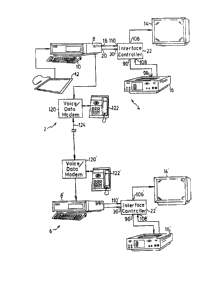
Referring now to Figure l, a remote teaching system
2 includes a teacher station 4 and a plurality of student
stations 6, only one of which student station is shown in
Fi.yure l for clarity.
The teacher station 4 comprises a digital
computer 8, which includes a keyboard lO, random-access
memory (not shown), a central processing unit (not shown) an
input/output channel (not shown) and a floppy ~agnetic disk
storage unit ~not shown)0 A suitable digital computer is the
'~IBM Personal Computer" commercially available from IBM
Corporation of Armonk, New York or the l'Professional 350"
pexsonal computer commercially available fro~ Digital
Equipment Corporation of Maynard, Massachusetts. A graphics
tabl~t 12 is connected to the input/output channel o~ the
digital computer 8 to permit graphics data to be entered into
the computer.
The teacher station 4 includes a video display
monitor 14 which is capable of displaying standard television
video signals. A video-tape cassette player 16 is capable of
*Trade-Mark
,
-14-
~3~
playing conventional video-tape cassettes to generate video
signals suitable for driving the video display monitor 14. A
æuitable video-tape cassette player 16 is the Model No. NV-
8170 video cassette recorder, commercially available from JVC
Company of ~merica of Elmwood Park, New Jer~ey. The personal
computar 8 has a computer video-signal output port 18 and a
printer output port 20. The computer 8 is capable of
generating video signals at the video-signal output port 18
suitable for driving the video display monitor 14. The
printer output port 20 is of the parallel interface type.
An interface controller 22 interconnects the
digital computer 8, the video-tape aassette player 16 and the
video display monitor 14 and, as described in detail below,
permits the digital computer ~ to control the operation of
the video-tape cassette player 16 and enables the computer 8
to select the source of the video signal for the video
display monitor 14.
Turning now to Figure 2A, a control-signal input
port 30 of the interface controller 22 has six control-signal
input terminals 31-36 together with a ground-connection
terminal 37. The control-signal input terminals 31-36 and
ground connection 37 of the control-signal input port 30 are
mounted within a connector adapted to mate with cable for a
parallel-interface printer. Each of the input terminals 3~-
36 is connected respectively to the input of an inverting
buffer 40-46. The six inverting buffers 41-46 are packaged
together in an integrated circui~ 40 of the 4049 hex buffer
type. A suita~le 4049 hex buffer integrated circuit is
marketed by RCA Corporation of Summerville, ~ew Jersey under
the trade designation "CD4049UB."
~3~3~3~7
The output of aach inverting buffer 41-46 i5
connected respectively to a light emitting diode 71-76. The
light-emitting diodes 71-76 are arranged on the face of a
cover (not shown) for the interface controller 22 to provide
an indication of the functioning of the controller. The
output of each inverting buffer 41-46 is also connected to an
actuating coil 87 of a five-volt single--pole single-throw
relay 81-86 across a series-connected diode 78. A parallel-
connected diode 80 is connected in parallel to the actuating
coil 87 of the relay 81-86.
A suitable diode for the series and parallel-
connected diodes 78 and 80 is signal diode type lN914. The
series-connected diode 78 isolates the output of the
inverting buf~er 41-~6 from the actuating coil 87 of the
relay 81-86. The parallel connected diode 80 tends to
suppress transient currents generated in energizing and de-
energizing the actuating coil 87. Each relay 81-86 has a
switch closure 88 which closes when the actuating coil 87 is
energized.
~0
A video-player control-signal output port 90 has
five video-player control-signal output tarminals 91-95
together with a common-connection terminal 97. Each of the
video-player control-signal output terminals 91-96
corresponds to a video-player control-signal input terminal
of a video-player control-signal input port 98 of the video-
tape cassette player 16. Electrical connection of a
particular video-player control-signal input terminal to a
common-connection terminal causes the video-tape cassatte
player 16 to per~orm a specific function in connection with
playing a video-tape cassette. The functions controlled by
the video~playar control-signal input terminals are start,
fast forward (scan~, reverse (scan), pause to display a
single-image frame, and stop. The video-player control-
-16-
~3~3~4~
signal output port 90 is adapted to be connected to the
video-player control-signal input port 98 of the video-tape
cassette player 16 by a six conductor cable so that each of
the five video~playar control-signal output terminals 91-95
is connected to a corresponding video-player control-signal
input terminal of the video-tape cassette player. The
common-connection terminal 97 of the video-player contrQl-
signal output port 90 is likewise connected to a common
connection terminal of the video-player control-signal input
port 95.
One side of the switch closure 88 of a video-signal
selection control relay 86 is connected to the supply voltage
Vcc. ~he other side of the switch closure 88 is connected to
an actuating coil 100 o~ a double-pole double~throw relay 102
across a series-connected diode 78. Two center movable arms
104 o~ the double-pole double-throw relay 102 are connected
to a two-terminal video-display-monitor video-signal output
port 106. One pair of contacts o~ the double-pole double-
throw relay 102 are connected to a two-terminal video-player
video-signal input port 108. The other pair of contacts of
the relay 102 are connected to a two-terminal computer
video~signal input port 110. When the actuating coil 100 sf
the double-role double-throw relay 102 is not energized, the
two terminals o~ the video-player video-signal input port 108
are connected respectively to the two terminals of the
video-display video-signal output port 106. When the
actuating coil 100 of the double-pole double-throw relay 102
is ~nergized, the two terminals of the computer video-signal
input port 110 are connected respectively to the two
terminals of the video-display-monitor video signal output
port 106. Thus the presence or absence of a control signal
on a video-signal-selection control-signal input kerminal 36
causes the video-display-monitor video-signal output port 106
'.X.
1~3~
to be connected respectively to th~ computer video-signal
input port 110 or to the video-player video-signal input port
108 of the interface ontroller 22.
Turning again to Figure l, a data-channel port of
an integrated voice/data modem 120 is connected to the
input/output channel of the digital computer 18. A speaker
telephone 122 is connected to a voice-channel port of the
voice/data modem 120. A suitable voice/data modem is
commercially available from Optel Communications Inc. of New
York, New York under the trade designation slVoice Too Modem."
A telephone-line connection port of the voice/data modem 122
is connected tc a telephone system symbolized by telephone
line 124 in Figure 1.
Each student station 6 includes a voice/data modem
120', a speaker telephone 122', a digital computer 8', a
video-display monitor 14', a video-tape cassette player 16',
and an interface controller 22'. Except for the programming
of the digital computer 8' of the student station 6, the
componen s of the student station 6 are essentially identical
to the corresponding components of the teacher station 4
described above and are interconnected in essentially the
same way. For conciseness, that description will not be
repeated.
Tllrning now to Figure 3, an alternative interface
controller 24 differs from the interface controller 22
discussed above in connection with Figures 2A and 2B in that
the output of each înverting buffer 41-46 is connected
respectively to a trigger input 50 of a corresponding
monostable multivibrator 51 56. For simplicity, only one of
the six inverting buffers 41-46 and only one of the six
-^'. ; !
.... .
-18-
~3~3~ 1L7
monostable multivibrators 51-56 is ~hown in Figure 3, the
other five inverting hu~fers and the other five monostable
multivihrators being connected identically.
As shown in Figure 4 t the monostable multivibrator
51 includes an integratsd-circuit timer 60 configured as a
monostable multivibrator. The integrat~d-circuit timer 60 is
one half of a dual integrated-circuit timer of the 556 timer
type. A ~uitable integrated circuit t.imer is marketed by
Signetics Corporation of Sunnyvale, California under the
10 trade designation ~SE556 Dual Timer.~ A threshold input 61
of the integrated circuit timer ~0 is connected to a positive
supply voltage Vcc of about 5 volts across a resistor 62
having a resistance of about lOOkn. A reset input 63 of the
integrated circuit timer 60 is tied directly to the supply
voltage Vcc. A discharge input 64 o~ the integratecl circuit
timer ~0 is connected directly to the threshold input 61 and
is connected to signal ground across a capacitor 65 having a
value of 4.7~F. A control voltage input 66 is oonnected to
signal ground across a capacitor 67 having a value of O.Ol~F.
The supply voltage te~minal 68 and the ground return terminal
69 of the integrated circuit 60 are connscted respectively to
the supply voltage Vcc and to a signal ground. The
monostable multivibrator 60 produces a pulse approximately
msec long at a pulse output 70 in response to a trigger
signal applied to the trigger input 50.
Turning again to Figure 3, the output 70 of each
monostable multivibrator 51-56 of the alternative interface
controller 24 is connected respectivel~ as the output of the
corresponding inverter buffer 31-36 of the interface
controller 22 of Figures 2A and 2B is connected. As noted
above, the remaining circuitry of the alternative interface
controller 24 is identical to the circuitry of the int~rface
, ~ ,
--19--
~3~3~147
controller 22. Reference is made to Figures 2A and 2B and
th~ corresponding discussion above for a d~scription of such
circuitry.
In order to maintain a switch closure 8~ o~ a
particular relay 81-86 in a closed configuration in the
alternative interface controller 24, a train of trigger
pulses is applied to the corresponding control-signal input
terminal 31-36. So long as the spacing between the trigger
pulses is greater tban the lenyth of the pulse of the
monostable multivibrator 51-56 by an amount less than a
response time of the correspondi~g relay 81-86, the switch
closure 86 of the relay remains in a closed configuration.
The digital computer 8 can be programmed to generate such a
train of trigger pulses on a particular terminal of the
parallel printer port 30 in order to control the functions of
the video-tape cassette player 16.
The pre~erred remote teaching system 2 of Figure 1
may be used to conduct a teaching session as follows. Video
cassettes containing essentially identical copies of a
video-taped lecture are distributed to each of the student
stations 6 and to the teacher station 4 in advance of the
teaching session. At the start of the teaching session, the
integrated voice/data modems 120, 120' of the teacher station
4 and the various student stations 6 are interconnected over
the telephone system 124 in a conference-call telephone linkO
Thus the students at the student stations 6 and the teacher
at the teacher station 4 can communicate by voice over the
speaker telephones 122, 122'. At the instruction of the
teacher over the speaker telephones, the students load the
video-tape cassettes of the video-taped lecture in the
video-tape cassette players 16' at the student stations 6.
~ .
~3~3~L7
Similarly, the teacher loads his or her video-tape cassette
in the video-tape cassette player 16 of the teacher
station 4.
In advance of the teaching session, floppy magnetic
disks containing a slave video-display control program are
distributed to each student station. F.ach student loads the
slave video-display control program into the digital computer
8' at his or her student station by inserting the floppy
magnetic disk into the floppy-magnetic-disk storage unit of
1o the digital computer ~' and entering the appropriate commands
for loading a program on the keyboard of the computer.
At the instruction of the teacher over the speaker
phones, the students at the student stations 6 initiate the
execution of the slave video-display control program stored
in the memories of the digital computer 8' at the student
stations. The teacher initiates a master video-display
control program stored in the digital computer 8 at the
teacher station 4. Upon initiation, the video-display
control programs cause each interface controller 22, 22' to
connect the computer video-signal input port 110 of the
controller to the video-display-monitor output port 106, so
that the associated video display monitor 14, 14' displays a
graphic start-up display from the computer to verify proper
operation of the computer and the video display monitor. The
video display programs also cause the video-tape cassette
players 16, 16' to rewind the video tapes to an initial
position.
The teacher then enters a video-tape start command
through the keyboard 10 of the digital computer 8 at the
teacher station 4. In response, the master video-display
program causes the interface controller 22 of the teac~er
station 4 to connect the video-player video-signal input port
108 of the interface controller to the video-display monitor
video-signal output port 106. The master video-display
program also causes the video-tape cassette player 16 to
begin playing the video-tape cassette mounted in the player.
The program also causes a video-player-start control-signal
communication command to be transmitted to the voice/data
modem 120, which, in response, transmits a t~lephonic video-
player start-control~signal over the telephone system 124
substantially simultaneously to the voice/data modems 120' of
each of the skudent stations 6. The voice/data modem 120' of
each of ths student stations 6 in response transmits a
video-player-start control-signal control command to the
associated-digital computers 3' of the student station 6.
The slave video-display control program interprets the
video-display start control-signal control command received
from the voice/data modem 120' and causes the digital
computer 8' to transmit control signals to the interface
controller 22' at the skudent station to connect the video-
player video-signal input port 108' of the interface
controller to the video-display-monitor video-signal output
port 106'. The slave video-display control proqram also
causes the computer 8' to transmit a control signal to the
video-display start-control-signal input terminal 31 of the
interface controllar 22', which in turn causes a video-
display-start relay 81 to close. The video-tape cassette-
player 16' at each student station 6 is thus caused to beginplaying the video-tape cassette. Thus, video-tape cassette
players 16, 16' o~ each of the student stations 6 and the
teacher station 4 begin playing the video-taped lecture
substantially in synchronism. Similarly, the master video-
display control program running on the digital computer 8 atthe teacher station can be used to cause the video-tape
casette players 16' at the student stations to scan forward,
scan reverse, pause to display a single image frame, and
~, ~
-22-
~3~3~
stop all essentially in synchronism - with the sam~
functisns performed by the video-tape cassette player 16 at
the teacher station 4.
A listing of a master video-display control program
for an "IBM Personal Computer" is attached hereto as Appendix
A and made a part of this specificatiGn" A sla~e video-
display control program for the ~-ame computer is attached as
Appendix B and is also made a part of this specification.
It is not intended to limit the present invention
to the specific embodiment described above. For example, the
speaker telephones of the teacher station and the various
student stations can be connected by a ~irst conference-call
telephone link and modems of the stations can be connected
over a second conference-call telephone link. Timing signals
can be recorded on the audio channels of the video tapes and
monitored by the digital computers so that the computer can
locate identical portions of the tapes by means of the timing
signals. It is recognized that these and other changes may
be made in the remote teaching system ~pecifically described
herein without departing from the scope and teaching of the
instant in~ention and it is intended to encompass all other
- embodiments, alterations, and modifications consistent with
the invention.
- !
~ 3~ 7
3675-OlO APPENDIX A
Mastex Video-Display Control Program
Q.:~tvDe vi o . asb
Fi l e not f ound
A,dir
VC)1L~me in drive Q has no label
8ire~tc:rv of h: \ -
VIF~ ~5~&C~O l-C)1-8~ 04a
PE EXE456~6 1~ 8-82 l?:C)()p
PE PF:Q -28- 4-~7-84 4: ~Ba
L I N~... EXE 58144 -.-07~85 l:~p
VIP OE~J ?lbS l-ol--BQ l~:C)6a
VIF~ EXE 1~0 1-~:~1-80 17:06a
VIP~ ASt1 b778 1-~:)1~80 12:1C)a
VIP~ OPJ 1240 1-C)1-8(:) 12:11a
VIP2 E:~E 1440 1-~:)1-80 l~:lla
F;VIP ASM l.-.q5l l-C)l-8(:) 12:17a
PVIP O~J 2C175 l -C) l -8C) l ~: 16a
t`lOe~EM QSM .~125 l -l:) l -80 l ~': I:~C)a
MODEl1 O~J 447 1~ 80 1'2:C)Ia
MODEM EXE lO24 l-~:~l-OO l2: Ola
TEt1P QSM 12444 1-~:~1-80 l:C)2a
FINAL 1:~2q~:~ l-01-8C~ l2:5la
16 File(s~ 1&5888 bvte~ free
~v~ --~3--
~384~
Q>
~type vip.asm
; THIS IS THE ~AIN PROGF:AM
: TO CONThOL ONE VCR
STACh' SEG11ENT PQRA 5TACN 'STQCh''
D~ 256 DUP (1:))
STACh'. ENDS
EXTF:Q SEGMENT PQFA FU~LIC 'EXTPA~
EXThA ENDS
DATA SEGMENT FARA FU~LIC ?DATQ~
BUFFEPS FOF SIMFLE INF~UT/OUTPUT :
-- ------_________
INBUF D~ 1 GUP ~CI) ; ~UFFEP FOR INPUT C011MAND
~UTTON DD 1 DUP O~ UFFER FOR STATU5 DYTE Fh~OM PQD
LOOK UF' TAPLE :
--____
TA~LE DW 5~
DW PLAY
DW 6D
DW 9TOP
DW 61
DWFOF:W~RD
DW 62
DWFEWIND
DW 6-~.
DW HOLD
DW 64
DWSChEEN
DW 65
DW DF~AW
DW 66
DW ~YE
CQOF;DINATE FOF: D~AW LINE POUTINE :
------_ _______
;
Xl DW C~
X2 DW C)
Yl DW D
Y2 DW C)
DELDY DW D
DELDX DW 1'.)
DELS DW Ct
DELP DW O
DELSX DW O
DELSY DW 1:
DELSE DW 1:
DELDE DW 1)
~ DATA FOk DP~W TO F:OUTINE :
----_______
XL GW 1)
yL VW ~
A .
~3~3~3~7
; DATA E~UFFER FOR CONVEfiSlONS
T~UFF DB ~O DUB ~O)
END SESSIDN FLQG FOR FROCEDU~E ~YE
ENDFLQG D~ l DUP (O)
DQTA ENDS
;
CODE SE6i1ENT PQF:Q PIJBLIc CODE~
MQIN PROC FAR
INITIALIZE
OPEN FILE AND 6ET FILE HQNDLES
-- ----__________
ASSU11E CS:CODE : INITIALIZE PSP
PUSH DS : ~RROGRAM SEGMENT RFEFIX)
MOV AX.D
PUSH AX
MOV AX~DATA
MOV DS~AX
ASSU11E DS:DATA
~10V AX.(:lB8(~ H
MOV E5.AX
QSSU~lE ES:EXTFA
CQLL IN7
CLE~fi THE h~EYBOQfiD BUFFEFi~ND
. 6ET Q COMMAND FF:OM l::EYBOARD
----________
.START: CALL INCOM : CALL PRQCEDURE INPUT-COMMAND
ii
; BF:ANCH TO APPF:OPRIATE
: COMMAND SUDF:OUTINE
----_____
CALL DRQNCH ; CQLL PfiOCEDUF;E BPANCHING
i JU11P BACK TO 6ET Al`lOTHER C0l111QND
__ ___________
CMP ENDFLA6~
JE STQRT i JUMF TO START
RET
i
; fiOUTlNE TO FLAY THE ~JCfi
PLAY PF;OC NEAR
PUSH AX j SQVE REGISTOF:S
MOV AL.C~lH ~ TURN QN FLAY
CALL PPlOUT
~l3~3l~l47
MOV QL, D ; TUFi~N LED OFF
CQLL PP 1 OUT
MOV QL, 59
CQLL Cr'i I COM
POP QX
F;ET
PLQY Et`iDP
FQUTINE TO STOP EiOTH F~EMOTE QND LOCQL VCF;S
STOP PF:OC NEQF .
PUSH QX i SQVE F~E6ISTOFS
MOV QL, 1 DH
CQLL PP I OUT
MOV QL ~ 11
CQLL PP 1 OUT
MOV QL, 60
C~iLL CM' ICOM
i
F'OP QX
RET
STOP ENDP
ROUTII`IE TO DO FQST FORWQFD AND FORWAF~D SCQN
FOF~WQF D PF:OC NEPIR
PUSH AX i SQVE P'E6I5TOFS
MC)V QL, ~:)2H
CQLL PP 1 OUT
i
MOV QL . 61
C&iLL CM 1 COM
pop ~iX
PET
F OF:W~F;D ENDP
FROUTII`IE TO DO fQST F;EWIND QND E~aC~CWQFD SCQN
F~EW I ND F F:OC NEQP
PUSH QX ; SQVE F;EG I STORS
MOV QL ~ D4H
CQLL PP 1 OUT
i
MOV QL,S~
CQLL CMlCOM
pop ~iX
~3~3~7
RET
FEWIND ENDF
ROUTINE TO F'~USE ~HOLDING)
~ HOTH REMOTE AND LOCAL VCRS
HOLD FROC NEAR
; PUSH AX ~ S~VE fiEGlSTDRS
MOV AL.I:)BH
C~LL FFlOUT
MOV AL,C)
CALL PPlOUT
MOV AL.o~.
- C~LL CI11COM
FOF AX
RET
HOLD ENDF
; fi~OUTINT TO SWITCH SCREEN
5CREEN FROC NEA~'
F'USH AX ; S~VE F;EGlSTUfiS
MOV AL~.C)H
5ALL PFlOUT
MOV AL ! S4
CQLL CI11COM
POF AX
RET
5CREEI`I EI`IDF
! ~OUTINE TO END SES5ION
~YE PROC NEAR
MOV AH~C) j SET DISFLAY TO -~0:~200 COLOh
MOV ~L,l
INT lOH
MOV ~L ! 60
CALL CMlCOM
110V AL, C)'~C)H
C~LL PPIOUT
MOV ENDFL~6.'-.)FFH
RET
~YE E~`IDF
i
.. . .. .
~3~3l~
; F~OUTINE TO USE ELECTRIC CHQL~' ~OQPD
; ~ THE DRQWING F;OUTINE )
DRQW FkOC NEQR
FU5H QX ; SQVE PESTORES
PUSH ~X
FUSH CX
FUSH DX
MOV QH~O : INITIQLIZE GF;~F'HIC SCREEN
MOV ~L~6 . 640::20C) ~LQCK QND WHITE
INT l-.\H
i
CQLL FQDGO
MOV QL~65
CQLL CMlCOM
; CQLL SCPEEN ; SWITCH DISPLQY FF;OM VCR TO C0~1PUTEP
F`TA: MOV QX~C~8l'.)C)H
MOV ES~QX
C~LL CLS ; CLEAR VIDEO RAM
FTP: CQLL 6ETP'r ; CALL THIS POINT P ~ONE)
MOV QH~(:)r~H ~ CHECK KEY~QQRD
INT ~lH
CMF~ OECIDE ~ IF THEF`E IS h~.EY~OQfiD ENTF~Y
TEST ~UTTON~l
JE FTB
CMF SI~64':l
.JNC PTG
CMP r, I ~ 44C~
JNC PTP
CMP DI~4l:
JC PTG
MOV XL,SI
MOV YL.DI
MOV C~UTTON,C
CQLL OUTPT
;
PTr~x: CQLL GETFT
TEST ~UTTON,l
JE FT~
;
C11F SI.640
JNC PT~X
CMF` DI.44C
JNC FT~X
CMF DI~240
JC FT~X
i
CQLL DF;QWTQ
CALL OUTFT
JMF' F.'T~X ~ 50 CHECh'. k::EY~OQRD
~ 8 ~
~3~138~
; ; AFTEF PLOTTING A POINT
DECIDE: CALL INCOt1
MOV AL ! IN~UF
CMP AL ~ ; IF EXIT
JE DONE t JUMP OUT
CMP AL~7 ; IF CLEAR-SCPEEN
JNE PT~
a
MOV AL~7
CALL CMlCOM
JMF~ PTA
; i JUi1P TO POINT 1 TO PLOT ANOTHEF; POINT
DONE: MOV AL~C)
CALL PF~l OUT
CALL PADHOLD
MOV AL ~
CALL C~lCOM
POP DX j F:ESTORE RE61STORS
pop CX
pop bX
poP AX
RET
GP~W ENGP
;
; ROUTINE INPUT-C0~11ANG TO
; CLEAR THE l::EY~OAFD PUFFEF;
; AND TA~CE A ~::EY FROM THE
KEY~OARD
INCOM PROC NEHfi~
PUSH QX j S~VE RE61STOF~;
PUSH DX : SAVE F;EGISTOR
PUSH CX j SAVE F;EGISTOF:
PUSH DX t SAVE REGISTOP
i
MOV AH~ lH
INT 71H
MOV IN~UF~AL ; AL CONTQINS THE INPUTED CH~R~CTEF
POP DX i RESTORE F:EGISTOR
POP CX ; F:ESTORE FEGISTOF
POP bX ; RESTORE F;E61STOR
POP RX . F;ESTOFE REGISTO~
F;ET
;
INCOM ENDP
;
; F.~OUT I NE TO bRANCH TO THE APPF;OF~FIATE FOUTINE
~ ~caNTF~oLLING THE VCP~)
PRANCH PF;OC NEAF;
PUSH ~X
g
~3~3~
RUSH ~X
F-USH CX
F-USH DX
MOV CX~8 ; TOT~L NUME~E~ OF COMM~NDS ~VhIL~BLE
.~10V EIX, I~
MOV ~H O
MOV hL INPUF ; LOOK UP COM11hND FROM KEY~O~RD
JE FOUND j JUMP OUT IF FOUND
INC E~X
INC ~X
INC BX
~NoCop A6~IN ; LEhVE IF NO SUC~ COMl1hND
FOF DX
F-OF- CX
F-OP ~X
F-OF- hX
RET
FOUt`lD: INC EIX : C~LL THE 5UPROUTINE
INC EIX
CQLL ThE~LE~E~X~
FQF- DX j RESTORE REGISTORES AND LEhVE
F-OP CX
FOP ~X
F-OF hX
PET
Elfi~t`lCH ENDF-
;
j ROlJTIl`lE TG CLEhF~ SCREEI`I
CLS FF:OC NEl~F
F-USH CX
F-USH ~X
i
11CIV CX . ~ H
~10~ X . I'J
MOV ~I.HX
CLD
REF STOSW
i
POF hP.
F-OF- CX
- RET
CL5 EN~P
: ROUTINE TO F-LOT ~ POINT ON THE ~C~::20(:
. ~LhCk3 hND WHITE HIGH RESOLUTION SCREEN
: ~UFOI`I ENTRY : -
SI: X-COOF:DIN~TE
~ DI: Y-COOfiDINhTE
SETPT F-ROC NEhR
PU5H hX ~ S~VE F;E6ISTOR
~7
~31113~
PUSH CX
FUSH DX
MOV CX~SI
MOV DX DI
~OV AH 12 ; FLOT ~ FOINT
MOV AL,l
INT lOH
REJECT: FOF DX
FOP CX
FOF AX i F;ESTQFE FEGISTO~
RET : AND LEAVE
SETFT EI~DP
i
; fiOUTlNE TO DFAW A LINE
SETLINF FROC NEAR
;
FUSH ~X j SAVE RE6ISTERS
FUSH CX
FUSH DX
FUSH SI
FUSH DI
FUSH AX
SET UF' X AND Y UFD~TES
~OV SI~l ; 5TAFT WITH FOBITIVE 1 FOR X UFDQTE
110V DI~l
FIND IY2-YlI
MOV DX,Y2
SUD DX,Yl
JGE STOREY
NE5 DI
NEG DX
STOREY:
MOV DELDY,DI
;
FIND 'X2-XlI
MOV CX,X2
SU~ CX, X 1
J5E STOREX
NEG Sl
NE6 CX
STOREX:
MOV DELDX.SI
SOPT IY2-Yll AND IX2-XlI
CMP CX,DX
JGE SETDIAG
~OV SI Cl
XCHG CX DX
JMF STOREDELSXY
SETDIAG:
~OV DI.I:)
: STORE DELS, DELP, DELSX,AND DELSY
STOfiEDELSXY:
~OV DELS,CX
.
,, ,
~ .3 1 --
~3~3~7
tlOV DELF,UX
MOV DEL5X,SI
MOV DELSY,DI
; GET INITIQL VALUES FOR X QND Y
MOV SI X1
MOV DI~Y1
COt1PUTE INITIAL VhLUE QND INCREMENT5 FOR ERROR FUNCTION,
MOV QX DELP
5QL AX~l
MOV DELSE QX
SU~ ~X, CX
MOV r~x . hX
SUB AX.CX
MOV DELDE.QX
. , QDJUST COUNT
i INC CX
j tqhIN LOOP STRUCTUF~E
LINELOOP:
CQLL SETF T
CMP BX l:l
JGE r, IQGONQL
! CASE FOR STRQIGHT MOVE
STFRQIGHT:
` QDD Sl,DEL5X
QDD DI.DELSY
QDD BX.DELSE
LOOP LINELOOP
JMR LItlEEXIT
- , ChSE FOR DIQGONAL t10VE
r; IAGOt`iAL:
ADD SI.DELDX
~DD DI,DELDY
ADD BX,DELDE
LOOP LINELOOP
i
LINEEXIT:
POP ~X
pop DI
POF` SI
pop DX
F`OP CX
POP ~X
RET
5ETLINE ENDP
; ROUTINE TO DRQW Q LINE FfiQi1 LQST PQII~T TO CURRENT POINT
DfiAWTO F`ROC NEQR
PUSI-I ~X
r
Z_
~L3~ 7
MOV AX~XL
llOV Xl.~X ; LAST POINT
MOV AX.YL
MOV Yl.AX
MOV X2,5I ~ CUfifiENT POINT
MOV Y2,DI
M~oOVv XL 5I ; UPDATE LAST F'OINT
CALL SETLINE
F~OP AX
F;ET
DfiAWTO ENDP
CMlSTF' F~F;OC NEA~
PUSH DX
PUSH AX
MOV DX~-.FbH
MOV ~L,80H
OUT DX~AL
MOV DX,-~F8H
MOV AL,~OH
OUT DX~AL
MOV DX~3F9H
MOV AL.1:)1:)H
OUT DX t AL
MOV DX ! .~FbH
MOV AL.03H
OUT DX.QL
i
i~OV DX,~.FCH
MOV AL.O-~H
OUT DX.~L
i
pop AX
F~QP DX
~ET
CMlSTP ENDP
CM25TP FkOC NE~F;
PUSH DX
PUSH ~X
MOV DX,2F~H
MOV AL,aOH
OUT DX~AL
MOV DX~2F8H
~10V AL":~CH
OUT ~X~L
MOV DX~2F~H
MOV AL,~ )H
OUT DX,AL
MOV DX~2FbH
1-1QV AL,C).~H
OUT DX,~L
pop AX
.~
-33--
~3~3~3~7
pop DX
FiET
CM~STP ENDP
CM1C011 PROC NEAF~
PUSH AX
MOV AL,~7
CALL CMlOUT
POP QX
CQLL CM1OUT
RET
CM1COM ENDP
PP10lJT FROC NE~R
PUSH DX
MOV DX ! D~.78H
OUT DX~AL
pop DX
RET
F'P10UT ENDr-~
CMlOUT F'ROC NE~R
PUSH DX
PUSH ~X
MOV DX.~FDH
LP2: IN QL~DX
QND QL~(:)H
JE LP2
MOV DX~3F8H
POP ~X
OUT DX~QL
pop DX
F~ET
CMlOUT ENDP
Cl11IN PROC NE~R
PUSH DX
MOV DX~.;FDH
LP-.: IN AL,DX
AN~ QL.1H
JE LP7
MOV DX ! 3F8H
IN QL.DX
ROP DX
RET
CM11N ENDP
CM20UT PROC NEAR
PUSH DX
PUSH QX
MOV DX.2FDH
LP4: IN AL.DX
~ND QL.2('JH
.,
~313~47
JE LF4
MOV D X ~ 2F 13H
POP ~X
OUT D X AL
F OP DX
F;ET
CM~2OUT ENDP
C112 I N F ROC t`lEP I~
F USH DX
MOV DX 2FDH
LP5: IN QL. DX
AND AL 1 H
J E LP5
MOV DX . 2F8H
IN AL. DX
F OF DX
F;ET
CM2 1 N ENDP
VOUT F ROC N EflR
PUSH DX
F USH AX
MOV DL ~ AL
MOV AH . ~?21-l
INT 21H
POF AX
l:OP DX
F;ET
VOUT ENDF
j F;OUTINE TO INITIPILZE SUI111A-St;ETCH
Pf~D I NZ PROC l`JEAF;
F USH QX
PUSH DX
MOV AL O j RESET F ~D
CALL :::M20UT
MOV AL. 44H ; F:Et10TE RE~IUEST MODE
CALL CM20UT
110V P.L 4 ~H . INCFEI1ENT C01111AND
CP.LL Cll OUT
MOV ~L. 21H ~ INCF~EMENT VALUE
CQLL CM20UT
MOV QL 62H j $ET OR161N
CALL CM20UT
MOV F~L~ ~4H ~ RESOLUTION : lD~'.t I pi
C~LL Cl`l `OUT
t10V AL 45H j DELTA MODE
CQLL CM~OUT
~ 3~3~a7
MOV DX,2F~H ~ CLEA~ PQD OUTF'UT BUFFER
IN AL,DX
POP DX
POP ~X
F;ET
P~DlNZ ENDP
PAD60 PROC NEAF;
PUSH AX
MOV AL~llH ; ST~RT TR~NSMISSION
CALL C~1~OUT
P09 AX
F:ET
PADGO ENDP
PADHOLD F~F~OC NEAR
PUSH AX
MOV AL~I~H : ST~I`ID~Y
CALL CM20UT
POF' AX
F~ET
PADHOLD Et`lr)P
S FOUTINE TO GET POINT FF~011 THE PAD
GETPT PROC NEAR
PUSH AX
RUSH DX
MOV AL.5,:)H ! TF;IGGEF; C01111hND
CALL Cl'1201JT
F~ASS: CALL CM21N 3 CHECH ~IT 7 FOP F'HASIN6
TEST AL.9C)H
JE F~hSS
MOV DUTTON,AL
CALL Cl1~1N : PUT LOW BYTE OF X IN DH
MOV DH,~L
~OV DL.~'.)
CALL C11_~IN ; 6ET HIEH BYTE OF X
, MOV AH,l) ; F'UT IT IN hX
SHL DX~l 3 CQNCATINhTE
SfiHcL DAXX~l ` ' DIJMTFAClS2ND BlT THROUGH CF
'; SHL DX i : hTTACJ -~RD BIT THROUGH CF
FsCHL~ DXx l i ~TTACH ~TH ~ND 5TH E~IT
RCL ~X~l
SHL DX~l
F~CL ~X~l
~,
~38~L7
t10V SI~AX
CALL CM'` I N ; F UT LOW EiYTE OF Y I N DH
MOV DH, AL
MOV DL ~ C1
CQLL CM2IN ; GFT HIGH ~YTE OF Y
MOV AH ~ O
SHL DX, l ! SA11E QS X EXCEPT ONLY QTTAiCH ONE E'IT
SHL DX, l
F5CHLL DX 1 i ATTQCH ONE MOR FOINT
RCL AX~I
MOV Dl,AX
NOT D I
At`lD D I . 1.) l FFH
SUEI D I . 70
i
F OF' DX
POP AX
RET
GETF T ENDP
i ROUTINE TO CONVERT FROM Il`iTEFi1`iAL lb-EilT EiINARY TO QSCII DEClPtAL
DEC l ~OUT F ROC NE~R
F'USH DS
PUSH D I
PUSH DX
PUSH CX
PU5H AX
MOV AX . DATQ
MOV DS, AX
NUMe.ER I S 1 N DX
i INPUT THE DIGITS It`l Q EiUFFER
t10V CX~')
LE~ D I ~ TEIUFF
DEC 1 ~nUT 1:
PUSH C X
MOV AX, DX
MOV DX,O
MOV CX
DIV CX
J XCHG AX, DX
ADD AL,-.OH
t10V ~DI~,AL
INC DI
FOF CX
INC CX
CMP DX . O
J N ~ DEC l ~ OU T l
; DUMF THE E~UFFEfi OUT
DEC 1 ~OUT':~:
~,
"~
3~
DEC Dl
MOV fsL tDI~
CQLL VOUT
LOOP DECl~OUT2
pop AX
pqp CX
POP DX
POP DI
pop DS
RET
DECl~OUT El~sDF
F;OUTINE TO GET A POINT FF;011 SUMMQ-SP~ETCH
WHILE IT IS OPERf~TING IN DELTfl MODE
INZ PfiOC NE~F
CP.LL CLS
C~LL CtslSTP
ChLL Cl?STP
C~LL PflDlNZ
CALL PADHOLD
C~LL VCF;INZ
F;ET
INZ ENDP
VCPINZ kFOC NEflfi
PUSH ~X
~qOV AL.I.)lH
MOV DX.C1~7qH
OLT DX s~L
IqOV QL.C13~:H
MIOV ~ DX.~ 7~H
OUT DX.~L
POP s~X
F;ET
VCPINZ ENDP
OUTPT PPOC Nss~k
PUSH AX
PU5H DX
~10V DX~SI
SHL DLI1
P~CL DH l
SHL DL;l
F;CL DH l
TEST ~UTTON~l
JE NOTPUSH
AND DH~03FH
Ofi DH D4s:1H
MOV ~L.DH
sCfsLL CMlOUT
JMP LOsl~YTE
~3~ -
~L3~
~utr~ DH~ .FH
OR DH,(.)8~H
MOV QL,DH
C~LL CMIOUT
LOW~YTE:
5H~ DL~1
SHR DL,I
OF; DL~CICC~H
MOV QL~OL
CQLL CM1OUT
110V DX~DI
SHL DL,1
RCL DH~1
SHL DL~1
RCL DH~I
OR DH~OCI.)H
MOV ~L~DH
CpLL CMlûUT
SHR DL~1
5HR DL,1
OR DL~(:)COH
MOV QL~D~
CPLL CMIOUT
FOF' DX
POP QX
F;ET
OUTFT ENDP
MQIN El`IDF'
CODE ENDS
END MQIN
3~ ~
~3~
3G75-010 APPENDIX B
Slave Video-Di~play Control Program
typ~ rvi 1~. as~ .
THIS I5 THE l`lfilN F~F;OGFfi~1
TO CONTF:OL ONE ~CF;
STflClC riEG11Et~lT Pf F~A STf Cl~ STACfi~
D~ 2~5 DUP ~CI)
5TfiCh ENDS
EXTR~ SEGl1ENT Pf1PQ RU~LIC ~ E;~TR~
EXTRA ENDS
Df~T~ SE611ENT P~F:fi PU~LIC ~ [)QTA~
;
;
~UfFEF:S FOP SIl1PLE IPlPUT~OUTPUT:
__~____ ___ ______ ____________
;
I N~UF DE~ 1 DUP ~ l:D ; EIUFFER FOF~ I PIPUT C01111.qND
~UTTOPI GP 1 DUP ~ O )
;
i LOOfi UP T~LE:
-- --____
;
TPPLE DW 59
DWPLAY
DW
DWTOP
~W~1
DWFORWAF;D
DW~2
DWF;EW I ND
DW ~
DWHOLD
DW ~
DWSCfiEEN
Dl 1 ~5
DWDRQW
DW ~
DWPYE
COOFDlPlfiTE~: FOF: DF~qW LINE ROLlTIi`lE:
------_______
T
,~.,j
~.3q~3~
Xl DW O
X~ DW O
Yl DW O
Y2 DW D
DELDY DW C
DELDX DW O
DELS DW
DELP DW IJ
DELSX DW
DELSY DW O
DELSE DW C
DELDE DW O
j GATA FOfi Dfi~W TO fiOUTINE :
____ ___ ____ __ _______
XL DW C
YL DW C)
~ DATA BUFFEF: FOF 50NVEFSIQNS
TBUFF DB ~C) DLlP (c))
j END SESSION FL~G FOF: PF;OCEGUfiE BYE
ENDFLAG D~ l CUP (1:))
;
DATh ENGS
CO~E SEGl1Erl-r FQF:A PUEILIC ~CODE
MhIN PfiOC FAR
;
, INITIALIZE
j OPEN FILE hND EET FILE HhNDIES
_______________________________
ASSU11E CS:CODE ; INITI~LIZE PSP
PUSH GS : ~PFIOGPAM SEGMENT PF:EFIX)
~Q~ ~X.~:
PUSH ~X
MO~ ~X.DAT H
MO~ DS.~X
ASSUME DS:DATA
r~o~ ~x . I:)ss~ :)H
MO~ ES.hX
ASSUME ES:EXTF~A
CALL Il`lZ
j CLEAP THE l::EYBOAF:D BUFFEF: ~I`IG
: GET A COM~AND FF;OM IEY~OAPD
_ _ _ _ _ _ _ _ _ _ _ _ _ _ _ A _ _ _ _ _ _ _ _ _ _ _ _ _ _ _ _
STAF:T: ChLL INCQi1 : CALL PPOCEDUF:E INF)JT-C011MArlD
; BF:QNCH TO AF-FFOFF:IATE
. COMMhND SUBPOUTINE
_________________________
C~LL ~F:hl`lCH : CALL F~F:OCEDUfiE ~F~hNCHIl`lG
~.3~38~7
~ JUMF ~ACl. TO GET hNOTHEF: COMMhNG
___________._____________________
CMF ENDFLAG./:i
JE ST~F:T : JU11F TO SThRT
FET
fiOUTINE TO FLhY THE VCR
iLhY FFOC NEAF:
PUSH hX : SAVE REGISTORS
MOV ~L.OIH ; TUfiN ON FLhY
ChLL PPIOUT
11QV AL.~ TURN LED OFF
i CALL FPIOUT
POP hX
F:ET
PLAY ENDP
; fiOUTINE TO STOP i~OTH F:EMOTE QND LOOAL VCFS
STOF FROC NEAF.
PUSH AX : SAVE REGISTORS
MOV AL ! I I IH
i CALL FPIOUT
MOV AL.:)
CALL FFIOUT
FOF AX
F;ET
STOF ENDF
~ fiOUTINE TO DO FAST FOFWARD ~ND FORiJhFD SCAN
FORWAF:D FROC NEAR
PUSH hX ; ShVE FEGISTORS
~10V f~L . ~:)~H
CALL FPIOUT
FOP AX
hET
FORWAfiD ENGP
~ ROUTINE TO DO FAST FEWIND AND ~hCi~;WARD 5CAN
FEWIND FROC NE~R
PUSH ~X ; SAVE REi;ISTOfiS
2-~
~3~
MOV AL.D4H
CALL PPIOUT
pOP AX
fiET
h~EWIND ENDP
h~OUTINE TO PQUSE ~HOLDING)
, ~OTH hEMOTE AND LOCAL VCh~S
HOLD PF;OC NEAP
PUSH ~X ; SAVE F:EGISTO~S
MOV AL.l:)eH
CALL PPIOUT
MOV ~L,O
CQLL FPIOUT
POP AX
F:ET
HOLD ENDP
j h~OUTINT TO SWITCH SCF:EEN
SCF'EEN PhOC NEAP
PUSH AX j S~VE hEGlSTOhS
MOV flL.:~OH
CALL F~F~IOUT
POP ~X
RET
SCh~EEN ENDP
fiOUTIME TO END SESSION
PYE PPOC NEAfi
MOV QH.I) : SET DISPL~Y TO -.~I'J:t~C)C) COLOF
MOV AL,I
INT I~:~H
MiOV AL.I:~-.OH
C~LL PPIOUT
MOV ENGFLA6.('JFFH
F:ET
~'1E EN~P
a
F~OUTIME TO USE ELECTPIC CHAL~1 ~OAfiD
. ~ THE D~.AWIN6 hOUTINE
~F~i F'~OC
~3~38~a~
FUSH QX i 6QVE RESTOfiES
FUSH BX
FUSH CX
PUSH DX
.
MOV AH~C) ; INITIAL12E GRAPHIC SCREEN
MOV AL 6 ; 64C)::~C)C) PLhCh. hND WHITE
INT IC)H
CALL SCFEEt`l ; SWITCH DISFLfiY FROM VCfi TO COMfUTEfi
FTA: MOV AX C)~8:)1:)H ; FOINT ~(ZEfiO)
t10V ES AX
CALL CLS
j i COME TO HERE AFTEF: FLOT FOlt`lT
CfiLL Cl1lIN
MOV fiH fiL
QND AH~:)CI:)H
JE DECIDE
FTB: CALL Ct11It`l i CALL THIS FOIt`~T B ~ONE~
MOV AH.AL
AND AH I.)CC)H
JE DECIDE
;
CMF AH.C)CC)H
JE FTB
CAl.L GETFT
TEST ~UTTON~l
JE FT~
MOV XL ~I
tlOV ~L DI
FTBX: CALL CMlIN
MOV AH.AL
AND AH.C)COH
JE DECIDE
CMF AH.iCGH
JE PTBX
ChLL GETFT
TEST BUTTON~l
JE FTP
CALL DF:hWTO
JMF PT~X
DECIDE; ChLL CM1IN j EXECUTE COMMAND FROM KE~BOhfiD
CMP hL~66 : IF EXIT
JE . DONE j JUMF OUT
CMF AL.67 j IF CLEAR-SCREEN
JE FTA : JUt1P TO BEGINNING OF ROUTINE
JMF FTP
j j JUMP TO FOINT 1 TO FLDT ~NOTHEF FOINT
bONE: MOV fiL,CI : CLEf~R DRAW FLAG
ChLL FP1OUT
i
FOF DX ; F:ESTQF:E REGISTOfiS
PO~ GX
~r
~31D3~3~7
FOF ~X
FOP AX
RET
DFAW ENDF
; ROUTINE INFUT-C01111hND TO
: CLEAP THE i:E~OAFD BUFFEfi
j AND TA~E A ~I:EY F~OM THE
: IEYEIOARD
i
i
INCOM FFOC NEAP
PUSH AX ; SAVE FE6ISTOR
NOTFRONT:
CALL C~1IIN
CMP AL ~7
JNE NOTFFiONT
; ~
CALL CMIIN
MOV INEIUF.RL
FOP AX i RESTORE RE615TOF
F;ET
INCOM ENDF
i
; ROUTINE TO EIF.ANCH TO THE AFPfiOPF.~lATE FOUTINE
~CONTROLLIN~ THE VCR)
~R~NCH FFOC NEAR
FU~H AX
FVSH PX
FUSH CX
FUSH DX
MOV CX.S ; TOTAL NUM~ER OF COMMANDS AVAILA~LE
MOV EtX D
MOV AH.O
MOV AL.INE(UF
AGHINg CMP QX.TAE'LE~X~ ; LOOh UP C01111AND F~QM ICEYEOAF;D
JE FOUND : JUMF OUT IF FOUND
INC ~X
INC EIX
INC ~X
INC ~X
LOOR Q6AIN ; LEAVE IF NO SUCH COMMAND
FOP DX
F`OP CX
PoP e~x
FOF` AX
RET
;
FOUND5 INC ~X i CALL THE SUPROUTINE
INC ~X
CALL TA~LE e ~x ]
FOF DX j RESTOkE REGISTOF~ES AND LE~VE
FOP ~X
3~7t
F OF EIX
FOP QX
fiE'r
ElfilqNCH ENDF
fiOUTINE TO CLEfiF: SCFEEN
;
CLS F ~:OC NE~F;
PlJSH CX
F USH f~X
MOV CX,2(~ H
~lOV ~X":~
MOV DI~QX
CLD
~EP 5TOSW
POF AX
FOP CX
;
PET
;
CLS El`IDF
POUT I I`IE TO F LOT A F O I NT ON THE ~ (:)C)
: ElLPCt~ ND W11ITE HIGH F:ESOLUTION SCfiEEt`l
-UF ON ENTF Y
; S I: X-COOfiD I NATE
D I: Y-COOF:D I NATE
SETPT F fiOC NE~fi
PUC.H QX ; S~VE FE5I5TOF
F USH C X
F USH DX
;
t10V 5 X . S I
MOV D X D I
: MOV ~H,12 ; PLttT ~ POINr
MOV ~L,1
I NT I C~H
POP DX
FOP CX
F-OP AX ; F:ESTOfiE F:EG I STOfi
fiET AND LEAVE
SETF T ENDP
~ fiOUTINE TO DFQW A LINF
SETL I NE F ~OC NEfiF
;
FUSH r~x ; S~VE F;EGISTEF;S
PUSH CX
F USH DX
F USH S I
F USH D I
PIJSH AX
.
SET UF X fll~D Y UPDf~TE5
: - 4(D-
~ 3~ L7
MOV Sl,l ; STAPT WITH FOSITIVE l FOF; X UF'D~TE
MOV DI~l
; FIND IY~-Yl
MOV DX,Y?
SU~ DX~Yl
J6E STO~EY
NEG DI
NEG DX
STOFEY:
MOV DELDY.DI
j FIND IX~-Xl,
110V C X ~ `~ ?
SUEI CX,X1
JEE STOFEX
NE6 SI
NEG CX
STOFEX:`
~OV DELDX.SI
;
; SORT IY~-Yl' ~ND JX~-Xll
CMF' CX,DX
JGE SETDI~G
" ~lOV S I . (:)
XCHG CX,DX
JrlF STOFEDELSX`t
SETDIAG:
MOV DI ! C)
: STOFE DELS, DELP! DELSX,~ND DELSY
STOFEDELSXY:
MOV DELS.CX
NOV DELF.DX
MOV DELSX.SI
MOV DELSY,DI
; GET INITI~L VHEUES fOF X AND Y
MOV SI,Xl
MOV DI,Yl
, COMFUTE INITI~L V~LUE HND INCFE11ENTS FOfi EF~O~ FUNCTION
MOV AX.DELF
SAL AX~l
MOV DELSE.~X
SUEI f~X. CX
~IOV ~X,~X
.
SU~ ~X. CX
MOV DELDE.~X
i ~DJUST COUNT
INC CX
j MAIN LOOP ST~UCTUF~E
LINELOOP:
C~LL SETF'T
C~P BX O
.,
~ 4~
. .
~38~7
JGE DI~GONQL
~ CASE FOR STF;QIGHT ~IOVE
STRAIGHT:
~DD SI~DELSX
~DD DI ! DELSY
QDD BX.DEL5E
LOOP LINELOOP
JMP LINEEXIT
~ CQSE FOR DIQGONQ- MOVE
DIAGONQL:
~DD SI~DELDX
ADD DI.DELDY
QDD ~X.DELDE
LOOP LINELOOP
LINEEXIT:
pOP AX
pOP DI
POP SI
pOP DX
POP CX
POP PX
FRET
SETLINE ENDF'
~ fi~OUTINE TO Dfi'QW Q LINE Ffi'D11 LAST POINT TO CUFR~ENT POINT
DRAWTO PROC NE~fi'
;
PUSH QX
Cl1P SI.~4C
JNC ~PT
CMP SI.C
JC ~PT
Cl1P D I , 4 40
JNC DPT
Cl1P DI.24e~
JC ~PT
nov ~x. xL
MOV Xl.QX : LQST POINT
P10V AX.YL
~10V Y 1 . ~IX
~OV X?,SI : CUPRENT F'OINT
MOV Y7.DI
CQLL SETLINE
~PT: MOV XL,SI
MOV YL.DI : UPDQTE LQST POINT
POP QX
RET
DfiQWTO ENDP
CMISTP PF`'OC NEQR
PUSH DX
F~USH QX
.
X _4~-
~ 3(1 3~1~7
MOV DX~.-.FE(H
l'IOV I~L, Bl:)H
OUT DX ~ AL
t10V D X, -,F BH
MOV AL, 60H
our DX.QL
MQV DX . -~F5~H
n~ ~L . ':\OH
OUT DX . AL
;
MQV DX.-'FE~H
1`10'J ~L . ~
OUT DX,AL.
MOV DX.. -.FCH
1`10V AL . 01 H
OUT GX . AL
ROF QX
FOF DX
PET
CM l STP -ENDP
CM-STF~ F F OC NEAF:
PUSH DX
PUE;H hX
i
110V DX.':~F~H
rll~v P,L. 81:~H
OUT D X ~ QL
MOV D X . ~FBH
L. I:)CH
OUT DX. AL
i
~OV DX.-FRH
110~ hL . OOH
OUT G X . AL
MCI',' GX.'`FEIH
1`10V AL . ~ H
OUT 13X . hL
pOp P X
POP DX
F;ET
C1~1~STP ENDP
CMlCOM PfiOC NEQR
PUSH Q;~
FU9H DI
110V Dl,DX
. FRONT: MOV AL. CDI
CALL CM 1 OUT
? INC DI
LoOP Ffi~ONT
POP D I
POP QX
. F;ET
CM~Co~l ~t~
: .
....
~1 3~3~
F F I ou r F F;OC NEP~fi'
FUSH DX
MOV D X, 0~7CH
OUT D X . ~L
FOP DX
F;ET
i
F P 1 OUT ENDF
CMlOUT FF;OC t`lE/~F
F USH D X
F USH ~4X
MOV DX . ~FDH
LF~: IN f~L, DX
f~ND AL . ~OH
J E LP:2
.
MOV DX . -FBH
POP ~X
OUT D X, AL
FOP DX
F;ET
CM I OUT EPIDF'
CMl IN F'fiOC NEAr~
PU8H DX
MOV DX 1 -FDH
LP~.: I N ~L . DX
Qt~lD QL. lH
J E LP3
MOV DX.-.F8H
IN P~L.DX
FOF DX
RET
;
CM 1 I N Et`lDP
CM20UT F F'OC l`lE~fi
PUSH DX
PUSH AX
MOV DX . :2FDH
LP4: IN ~L. DX
Flt`JD QL, ?C)H
JE LP4
110V 1: X, ~FE'H
FOP QX
OUT DX ! flL
PoP DX
F;ET
CM20UT ENDP
CM2 I N PPOC NE~fi
PUSH DX
MOV DX . ~FDH
LPS: IN ~qL. DX
~`ID f~L, lH
. .
,".. .:
~3~3~l~7
.
JE LF5
MOV DX.2F8H
IN ~L~DX
FOF DX
fiET
C~2IN ENDF
VOUT FFOC NEQR
FUSH DX
FUSH AX
MOV DL,~L
MOV AH,Ij2H
INT 21H
FOF AX
FOF DX
fiET
;
VOUT ENDP
i fiOUTINE TO EET FOINT FFOM THE FAD
GETFT FhOC NEhF
F-USH AX
MOV ~H.AL
MOV ~UTTON,C~
TEST AH.1:~4':\H
JE NOTF'USH
;
ADD ~UTTON~l
NOTFUSH:
CALL C111IN
SHL AL,l
SHL AL,l
AND AH,~ FH
SHfi AH,l
RC~ AL,l
5HR AH!l
F:Cfi ~L,l
~OV SI,AX
CALL CMlIN
MOV QH,AL
: CALL C111IN
3HL ~L~l
SHL ~L,l
AND ~H,O-sFH
SHfi pH.l
RCfi AL~l
SHF AH,l
F~Cfi ~L~l
MO~ Dl,~X
FOF AX
RET
GETFT ENDF
FOUTINE TO CONVEfiT F~OM INTE~NAL l~-~IT ~INA~Y TO A5CII DECIMAL
~Fcl~ouT F'ROC ~FJAR
:. . .
~3~3~7
PU5H D5
PUSH Dl
PUSH DX
PUSH CX
FUSH ~X
MOV ~X,D~T~
MOV DS,~X
NUMBEP IS IN DX
; INFUT THE DIGITS IN ~ BUFFEP
MOV CX~C)
LE~ DI,TBUFF
DEC160UTl:
FUSH CX
MOV ~X,DX
~OV DX.C
~lOV CX . 1 (:~
DIV CX
XCH~ ~X.DX
~DD AL.-.OH
MnV CDI~.~L
INC DI
POF~ CX
INC CX
Cl1P DX.C
JNZ DEcl~our
; DUI1P THE BUFFEfi OUT
.
DECl~OUT2:
DEC DI
MOV ~L.CDI~
CALL `~OUT
LOOP DECl~OUT2
i
POF AX
POP CX
FOF DX
PDF Dl
FOP DS
PET
DEC160UT EI~IDP
INZ FPOC NE~
CP~L~ CLS
C~LL CMlSTF
C~LL VCPINZ
PET
INZ ENDP
: VCF;INZ PPOC NE~P
: FUSH ~X
MOV ~L~C~H
MOV DX.':~.~79H
: OUT DX ~ QL
.
:. ...
~r
..,_ . ~
~L3~38~7
110V QL ~ C)H
MQV DX,C)~78H
OUT D X, QL
PCIF~ QX
F~ET
VCh~ I N Z Et`lDF~
MQ I N . ENDP
CODE ENDS
END ~1QI N
.,
- ~3~