Language selection

Search

Patent 1304784 Summary

Third-party information liability

Some of the information on this Web page has been provided by external sources. The Government of Canada is not responsible for the accuracy, reliability or currency of the information supplied by external sources. Users wishing to rely upon this information should consult directly with the source of the information. Content provided by external sources is not subject to official languages, privacy and accessibility requirements.

Claims and Abstract availability

Any discrepancies in the text and image of the Claims and Abstract are due to differing posting times. Text of the Claims and Abstract are posted:

  • At the time the application is open to public inspection;
  • At the time of issue of the patent (grant).
(12) Patent: (11) CA 1304784
(21) Application Number: 591700
(54) English Title: OPTICAL COMMUNICATION APPARATUS FOR MOTOR VEHICLE
(54) French Title: APPAREIL DE COMMUNICATION OPTIQUE POUR LES VEHICULES AUTOMOBILES
Status: Deemed expired
Bibliographic Data
(52) Canadian Patent Classification (CPC):
  • 325/1
(51) International Patent Classification (IPC):
  • H04B 10/00 (2006.01)
  • H04B 10/10 (2006.01)
  • H04B 10/22 (2006.01)
(72) Inventors :
  • OKAZAKI, KUNIO (Japan)
  • ISHIKAWA, KIYOMITSU (Japan)
(73) Owners :
  • STANLEY ELECTRIC CO., LTD. (Japan)
(71) Applicants :
(74) Agent: GOWLING WLG (CANADA) LLP
(74) Associate agent:
(45) Issued: 1992-07-07
(22) Filed Date: 1989-02-22
Availability of licence: N/A
(25) Language of filing: English

Patent Cooperation Treaty (PCT): No

(30) Application Priority Data:
Application No. Country/Territory Date
63-24903 Japan 1988-02-26

Abstracts

English Abstract


Abstract of the Disclosure
An optical communication apparatus for motor vehicles
comprising: using a light emitting diode of a rear combination
lamp, marker lamp or the like as a light emitting element;
providing a light receiving element near at the light emitting
element; and connecting a transmitter to the light emitting
element and a receiver to the light receiving element.


Claims

Note: Claims are shown in the official language in which they were submitted.


THE EMBODIMENTS OF THE INVENTION IN WHICH AN EXCLUSIVE
PROPERTY OR PRIVILEGE IS CLAIMED ARE DEFINED AS FOLLOWS:
1. An optical communication apparatus for vehicles,
comprising:
at least one of a rear combination lamp and a marker
lamp on a first vehicle, said at least one of a rear
combination lamp and marker lamp including a light
emitting means for emitting a visually observable light
signal;
a source of optical communication signals, including
said light emitting means of said at least one of a rear
combination lamp and a marker lamp of said first vehicle
for use also for generating optical communications
signals;
light receiving means on said first vehicle and
located in the vicinity of said light emitting means for
receiving from a light source in a second vehicle optical
communications signals related to an original signal;
transmitting means on said first vehicle and coupled
to said light emitting means for causing said light
emitting means to also emit said optical communications
signals; and
receiver means coupled to said light receiving means
for converting said received optical communications
signals into substantially said original signal.

2. The optical communication apparatus of claim 1,
wherein said light receiving means receives optical
communications signals from said second vehicle.

3. The optical communication apparatus of claim 1,
wherein said light receiving means on said first vehicle
is located near said light emitting means of said first
vehicles.

4. The optical communication apparatus of claim 1,
wherein said light receiving means on said first vehicle


is located adjacent to said light emitting means of said
first vehicle.

5. The optical communication apparatus of claim 1,
wherein said transmitting means includes:
a microphone; and
FM modulator means for receiving input signals from
said microphone and coupled to said light emitting means
for causing said light emitting means to generate said
optical communications signals responsive to an FM
modulated output of said FM modulator means.

6. The optical communication apparatus of claim 5,
wherein said receiver means includes:
FM demodulator means coupled to said light receiving
means for FM demodulating optical communications signals
received by said light receiving means; and
audio output means coupled to said FM demodulator
means for producing an audio output in accordance within
FM demodulated output of said FM demodulator means.

7. The optical communication apparatus of claim 5,
wherein said receiver means includes:
FM demodulator means coupled to said light receiving
means for FM demodulating optical communications signals
received by said light receiving means; and
audio output means coupled to said FM demodulator
means for producing an audio output in accordance with an
FM demodulated output of said FM demodulator means.

8. The optical communication apparatus of claim 7,
wherein said FM demodulator means and said FM modulator
means operate with different carrier frequencies.

9. The optical communication apparatus of claim 7,


wherein said FM demodulator means of different vehicles
have different carrier frequencies.

10. The optical communication apparatus of claim 1,
wherein said light emitting means comprises at least one
light emitting diode (LED) serving for emitting said
visually observable light signal for said at least one of
said rear combination lamp and marker lamp and for
emitting said optical communications signals.

11. The optical communication apparatus of claim 1,
wherein said light receiving means comprises a plurality
of closely adjacent photodiodes.

12. A method of optical communication between vehicles,
comprising:
providing at least one of a rear combination lamp
and a marker lamp on a first vehicle, said at least one
of a rear combination lamp and marker lamp including a
light emitting means for emitting a visually observable
light signal;
providing a source of optical communications signals
including said light emitting means of said at least one
of a rear combination lamp and marker lamp, for use also
for generating optical communication signals;
generating an electrical communications signal
containing original information to be transmitted from
said first vehicle to a second vehicle;
emitting an optical communications signal
corresponding to said electrical communications signals
by means of said light emitting means;
receiving said optical communications signals at
said second vehicle;
converting said received optical communications
signals at said second vehicle into a signal


representative substantially of said original
information;
said second vehicle including light receiving means
located in the vicinity of a light emitting means of said
at least one of a rear combination lamp and marker lamp
of said second vehicle.

13. The method of claim 12, wherein said optical
communications signals emitted from said first vehicle
has a carrier frequency which is different from an
optical communications signals emitted from said second
vehicle.

14. The optical communication method of claim 12,
wherein said light emitting elements comprise at least
one light emitting diode (LED) serving as both a light
source of at least one of said rear combination lamp and
marker lamp, and for generating said optical
communications signals.

15. The optical communication method of claim 12,
wherein the receiving step comprises providing a
plurality of photodiodes closely adjacent to each other.


Description

Note: Descriptions are shown in the official language in which they were submitted.


- ~3~4~1

SPECIFICATIO~
O~tical Communication A~paratus for Motor Vehicle
Background to the Invention
(Field of the Invention)
The present invention relates to an optical communication
apparatus mounted on four-wheel motor vehicles for optical

communication among them.
(Prior Art)
If a plurality of persons move from one location to
another location, a plurality of motor vehicles are used. In
such a case, communication among them may be required
sometimes duriny such a trip, which communication should be
kept secret to third parties.
If a radio communication is used among motor vehicles,
there is a risk of leaking out the content of communication to
third parties, posiny a problem of leakage of secret.
Summary of the Invention
It ls therefore an object of the present invention to
~rovide an optical communication apuaratus for motor vehicles
capable of kee~ing secret during communication among theln.
According to an aspect of the present invention, an optical
communication a~aratus for motor vehicles comprises using a
light emittiny diode of a rear combination lamp, marker lamp
or the like as a light emitting element, providing a light
receiviny element near at the liyht emitting element, and
connectillg a transmitter to the light emitting element and a
receiver to the light receiving element.
Brief Description of the Drawings


` 1304784


The above and other objects and advantages of the present
invention will be described in more detail in the following,
by way of example, reference being made to the accompanying
drawinys, in which:
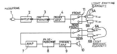
Fig.1 is a block diagram showing an embodiment of an
optical communication apparatus for a motor vehicle accordiny
to the present invention;
Fig.2 is a side elevational view illustrating how optical
communication is performed among motor vehicles; and
Figs.3 and 4 show the mounting condition of the light
emitting and receiving elements of the embodiment.
Detailed Description of the Preferred Embodiment
An embodiment of this invention will be described in
detail with reference to the accompanying drawings.
Figs.1 to 4 show an embodiment of the optical
communication apparatus for a motor vehicle according to the
present invention. Referring to the figures, reference numeral
1 represents a ~icrophone, 2 an amplifier for amplifying a
voice or audio siynal, 3 an FM modulator for FM modulating the
voice signal, 4 a power amplifier, and 5A and 5B a light
emitting element driven by an output from the amplifier 4. If
a rear combination lamp (refer to Fig.3) and front marker
lamp (refer to Fig.4) are constructed of light emitting diodes

(LEDsj, then LEDs are used as the light emitting
elements.
6A and 6B represent light receiving elements such as
photodiodes, 7 an amplifier for amplifying received siynal, 8


~304784

an FM demodulator for FM demodulating an output from the
amplifier, 9 a voice or audio signal amplifier for amplifyiny
a voice signal, and 10 a loudspeaker. The light receiving
elements 6A and 6B are mounted near at the rear combination
lamp (shown in Fig.3) and marker lamp (shown in Fig.4).
The rear, and front light emitting elements 5A and 5B,
and the light receiving elements 6A and 6B are interchanyeably
switched by using a switch 11, respectively.
In operation, for example, for communication between
motor vehicles A and B as shown in Fig.2, light pulses of a
carrier frequency fa modulated by voice is emitted out from
the light emitting element 5B of the motor vehicle ~ to the
motor vehicle B. The light pulses are received by the liyht
receiving element mounted at the front of the motor vehicle B,
amplified, FM modulated, audio-amplified, and supplied to the
loudspeaker 10 to yenerate voices.
On the contrary, light pulses of a carrier frequency fb
are emitted out from the motor vehicle s to the motor vehicle
A. The light pulses are received by the light receiving
element mounted at the rear of the motor vehicle A, amplified,
FM demodulated, audio-amplified, and supplied to the
loudspeaker 10 to yenerate voices.
Unless optical communication is not performed in full
duplex manner, a same carrier frequel1cy can be used in sending
and receiving light pulses.
As appreciated from the foreyoing description of the
present invention, although a service area is limited because
of optical communication, cross talk can be reduced. Further,


1304784


as the light emitting element, the LEDs of the rear
combination lamp and marker lamp can be used so that no
additional light emitting element for such particular function
is not used, resulting in low cost. In addition, by using
different carrier frequencies in sending and receiving light
yulses, optical communication can be realized simultaneously
among motor vehicles.
Although the present invention has been described in
connection with the preferred embodiment thereof with
reference to the accompanying drawings, it will be apparent to
those skilled in the art that various changes and
modifications of the present invention are possible within the
scope of the following claim.


Representative Drawing
A single figure which represents the drawing illustrating the invention.
Administrative Status

For a clearer understanding of the status of the application/patent presented on this page, the site Disclaimer , as well as the definitions for Patent , Administrative Status , Maintenance Fee  and Payment History  should be consulted.

Administrative Status

Title Date
Forecasted Issue Date 1992-07-07
(22) Filed 1989-02-22
(45) Issued 1992-07-07
Deemed Expired 2001-07-09

Abandonment History

There is no abandonment history.

Payment History

Fee Type Anniversary Year Due Date Amount Paid Paid Date
Application Fee $0.00 1989-02-22
Registration of a document - section 124 $0.00 1989-05-01
Maintenance Fee - Patent - Old Act 2 1994-07-07 $100.00 1994-06-01
Maintenance Fee - Patent - Old Act 3 1995-07-07 $100.00 1995-06-15
Maintenance Fee - Patent - Old Act 4 1996-07-08 $100.00 1996-06-18
Maintenance Fee - Patent - Old Act 5 1997-07-07 $150.00 1997-06-12
Maintenance Fee - Patent - Old Act 6 1998-07-07 $150.00 1998-06-30
Maintenance Fee - Patent - Old Act 7 1999-07-07 $150.00 1999-06-28
Owners on Record

Note: Records showing the ownership history in alphabetical order.

Current Owners on Record
STANLEY ELECTRIC CO., LTD.
Past Owners on Record
ISHIKAWA, KIYOMITSU
OKAZAKI, KUNIO
Past Owners that do not appear in the "Owners on Record" listing will appear in other documentation within the application.
Documents

To view selected files, please enter reCAPTCHA code :


To view images, click a link in the Document Description column. To download the documents, select one or more checkboxes in the first column and then click the "Download Selected in PDF format (Zip Archive)" or the "Download Selected as Single PDF" button.

List of published and non-published patent-specific documents on the CPD .

If you have any difficulty accessing content, you can call the Client Service Centre at 1-866-997-1936 or send them an e-mail at CIPO Client Service Centre.


Document
Description 
Date
(yyyy-mm-dd) 
Number of pages   Size of Image (KB) 
Drawings 1993-11-02 1 21
Claims 1993-11-02 4 143
Abstract 1993-11-02 1 11
Cover Page 1993-11-02 1 13
Representative Drawing 2000-12-21 1 10
Description 1993-11-02 4 120
Correspondence 1999-07-19 5 117
Fees 1996-06-18 1 35
Fees 1995-06-15 1 36
Fees 1994-06-01 1 52