Note: Descriptions are shown in the official language in which they were submitted.
1305200
I1tle
~elo~ded ~teering Ball JO1n~ A~B~ Y ~nd Method
Backaroun~ of the Inventlon
Thl6 lnvention relates to vehi~ular 6teerlng ball ~oint
a~emblies. More particularly, the invention relstes to the
preloading of 6uch a~6emblles for hchieving relatively con6tant
torque6 on the ball ~oint6 over the u6eful live6 of ~uch ~oint6.
A ~a~or requirement of ball ~o$nt6 a6 utllized ln ~teering
links and Bu6pen~lon ~y6tem6 i6 the ~alntainance of a relatively
con6tant rotating torque over the u6eful life of the ~oint.
Normally, a6 the u6eful life progres~e6, the rotating torque
decrea6e6 and teerlng wheel play and 06cillation6 tend to
lncrease to the detriment of vehicular operation. Attempts to
overcome ~uch unde6irable torque loss are numerous. For example,
coil eprlngs have been mployed wlthln the ball socket cavities
of ~olnt a-se~blle~ to urge bearing Dembers con6tantly agalnst
the ball. Iypically, however, the coil pring ha6 a low
compre6s$ve longltudinal la~tic ~odulu6, and the torques
con6equently cannot be ~et ~ufficiently high nough to meet
desired value6. Not only iB there a large reductlon of bearing
contact load under mall ch~nge6 ln part dimen610n6 due to
general wear and abr~6ion, but ln the proces6 of ~anufacture
there often re~ult6 a large deviation ln initially ~et rotating
torque value6. As a result, ball ~oint6 are rarely ~anufactured
with ~ati~factory con6i6tency in preload torque value6.
Moreover, ela6tomer member6 formed under in~ection or insert
1305200
~ol~ing t-chnlgue- hav~ al-o b--n ubetltut-d for coll prlngs to
comp-n-at- for th- ~all oo~pr-~-lv- long~tudlnal la-tlc ~odulu~
of coil prings However, although the u-e o~ la-to~er has
provlded eome i~provement, ~anufacturlng techn$quee for achievlng
consl~tency ln torque value~, r-gardl-s~ of tolerance varlation6
$n part elze6, have not yet been ati6factory
EY~mary of tbe Invent$on
The preloaded eteering ball ~olnt a--embly and ~ethod of the
present lnvent$on provide6 a ey6tem where$n 6 relatively
concictent torque valu- ~ay b- achlev-d ln p$te of fairly wide
tolerance ~ar$ations ln di~en~ion6 of part6 In a preferred
form, a preloaded ball ~oint a-~embly 1- formed whlch utilizes an
~la6tomer di~c formed by an lnsert ~olding proce66, ln6tead of
u6inq a co$1 epr$ng for pr-load$ng the upper or top bear$ng ~eat
of the ~olnt a~embly In a preferr-d form, the ~olnt a66emb1y
lnclude~ ball ocket and lntegral ball-ehaft ~ember6 wlth upper
and lower -~l--pberlcal b-arlng -at6 for po6itioning and
r-talning th- ball within the ock-t cavity However, the top
eeat contain~ an lnt-gral clrcu~ferentlally extending barrier lip
whlch, during the lneert ~oldlng proce66, prevent6 the flow of
~olt-n la~to~er fro~ nterlng the ball eockct cavity The llp
le angled radlally outwardly toward the lasto~er dl-c eo that a6
the preesure lncr-ae-~ durlng the lneQrt ~old$ng proc--s the lip
will expand outwardly again6t the eoc~et cavity wall Ideally,
-- 2 --
130~;200
the ~reat-r th- pr-~-ur- th- gr-at~r th- tend-ncy for the llp to
o acco~mo~ate the pr-~ur- Und-r a pre~-rr-d uethod, the
laetomer i- ln~ert nold-d lnto the cavlty to a pr-deter~ined
overflll dl~en~lon whlch xtendc abov- an lnt-rnal
circu~ferential houlder A Detallic dl~c 1- ln-tall-d atop the
ela6tomer disc to conpre66 the la6tomer dl-c agaln6t the top
eat a p-Qnlng proce~B i- utlllz-d to force the ~etalllc dlec
downwardly o a~ to cauee the dl-c to botto~ agaln6t the ~houlder
and to thereby compr~s6 the la~toner by the pr-deter~ined
dlnenelon to ff-ct d-elr-d torgue preload of the ball between
the bearing eat6
~ Brlef De6crlDtlon of the Drawinae
Flgure 1 1- a cro~6 ~ectlonal view of a preferred e~bodiment
of the ~teering ball ~oint as~embly of the pre6ent inventlon,
~hown durlng one tage Or ite ~anufacturlng proce66
Flgure 2 le a cro-e ectlonal lde vlew of the top bearing
eat ln the mbodl~ent Or Flgure 1
Figure 3 i- an nlarged view Or a circled portlon "A" of
Flgure 2
Figure 4 ie a bottom face view of the top bearing 6eat,
vlewed along llne~ 4-4 of Figure 2
Flgure S 1~ a cross eectlonal vlew of a completed teering
ball ~olnt a-~embly con~tructed ln accordance ~lth a preferred
proc-es Or the pr--ent lnventlon, hown wlth tolerance varlat~on6
- 130S200
of a-~e~bly part- at a ~axl~u~ accumulatlon
Flgure 6 1- a compl-t-d a-~-mbly vl-w l~llar to that of
Flgur~ 5, xc-pt that tol-ranc- varlatlon~ of ~-~e~bly partc are
at their ninlmu~ accu~ulatlon valu-
~etalled Descrlotlon of a Preferred Embodlment
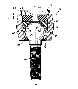
Ref-rrlng lnltlally to F~gure 1, a partially co~pleted ball
~olnt a~embly ~0 describ-6 a longltudlnal axl~ ~a-a~ about whlch
a cyllndrical houslng 12 defines upper and lower openlng6 11 and
13, r--p-ctlvely ~he hou-lng 1~ adapted for contalnment and
dynamlc r-ten-lon of a ball 14 whicb ha- an lnt-grally fixed
ehaft 16 xtendlng th-refrom The lnt-rlor of the hou6ing 12
deflne6 a ball ocket cavlty lS whlch contaln~ an upper or top
bearing ~cat 18 and an oppo~ed lower or bottom bearing ~eat 20
Each eat d-flne6 a ceml-cpberical m-mb~r adapt-d to oppo6ingly
ceat the ball 14 wlthln th- hou~lng 12, a~ hown
For purpo~-- Or pr-loadlng the ball 14 between the palr of
b-arlng ceat~ 18 and 20, an lactomer dl-c 22 1~ ~uxtaposed under
forc- agalnct the top b arlng eeat 18 In the lnventlon a5
d-~crlbed her-ln, the la6tomer dl~c 1~ forned by an ln6ert
moldlng proce~6 whlch 1~ de61gned to accommodate a varlatlon of
tolexance ln dl-enslon6 of the housing, ball, and bearing
me~ber~ ~he invention provides a ~ethod whereln molten
la-tomer 1B in~ert molded lnto that portlon of th- cavity 15
whlch 1~ above the top b-arlng c-at 18 by an amount which
- 4 -
~305200
~lightly ov~rfill- a elrcum~-r-ntlal ~houlder 24 wlthin the
eavlty Henc-, the top Or th~ di-c 26 upon eo~pl-tlon of the
lncert ~olding proce~ will be po61tioned ~bo~- the houlder 24
by a earefully pr~deter~ined amount of la6tomer, indlcnted as
n Z ~I in Figure l
Referring now to Figuree 5 ~nd 6, a co~pleted ball ~oint
~esembly 50 is 6hown whlch include~ a ~etallic disc 44
Referring ~omentarily back to Figure l, lt will be een that a
elreumferentlal elosure lip 28 whieh define6 the extremity of the
upper opening ll of the h4using 12 will, in the final eompleted
~ssembly 50, be peened over the d~c 44 to thereby eompres6 the
ela6tomer disc 22 by the a~ount egual to the ~ZH overfill
dimen6ion The dge6 of the di6c 44 wlll fully ngage the
ehoulder 24 upon the peenlng of the elo6ure lip 28 down over the
di6c
A ~aximum tolerance eondition i~ hown in Figure 5 Those
~ill-d in the art will appreciate that thi~ eonditlon will
produee the largest pos~ible ~iec thiekne66, repre6ented aB n X~l.
By eontra~t, Figure 6 ehowe ~ eompl-ted a-~e~bly 50 ln whieh the
toleranee varlation brlnge about the ~lnlnum ela6tomer disc
thlekne~6, repre6ented a6 ~y" In the embodiment6 of Flgures 5
and 6, the difference in the ~x" and ~y" dimension6, that i6, "x"
~inu~ "y", wa~ in the range of 70-80 thousandths of an inch,
while the ~z" dimen6ion wa6 approxi~ately 40 thoueandths of an
ineh The ~z" dimension reflect6 the amount of ov~rfill which
for preload torgue eonei~teney would be a eonstant value in a
given ball ~olnt a--embly na~Qc~ur~ng process Moreover, the
~z" dlmen-lon ln t~a pr-~-rr-d practlce o~ the ln~-ntlon wlll
vary only by one plu~ or alnu~ flv- thou~andth- of an lnch In
the mbod$~ent her~ln de~crlbed, preload pr-~ure range~ fell
- between 15 to S0 lnch-pounds of torque The ela-tomer di~c w~s
lnsert ~olded, and had a duro~eter value of ~pproxl~ately 52
In the preferred form, the top bearlng eat 18 can be formed
eithcr o a polyacetal material or of a teflon fllled plastic,
although other low frlction ~urface ~aterlal~ may be utilized
For example, the bottom eat 20 wa~ of a poll~hed teel for
rea~ons of mlnlmizlng fertillzer corr~61On ln the e~bodi~ent
de~crlbed
R-ferrlng now to Flgure 1, lt will be appr2ciated by those
ekllled ln the art that the ball ~olnt a~6embly of the present
lnvention mu6t be able to receive and to accommodate lubrication
over lt6 useful llfe For thi6 purpo6e, a pair of communicating
lubrlcatlon channel6 30 and 32 xtend through the top bearing
e-at 18 and the la~tomer dl~c 22, respectively (~ee Fig 1)
The channels permlt lubricant entry lnto a ocket cavity
lubrlcatlon or lubrlcant chamber 34, de~lned by the annular
epacing or gap between the upper and lower bearlng eat~ 18 and
A plurality of radlal lubrication pa66ageway6 36 extends
'~through the bottom face 38 of the top bearing seat 18 (Fig 4) to
allow pas6age of lubrlcant from the channel6 32 and 30 into the
~305200
c~a~ber 34 A6 ~pp~r-nt in Flgur- 1, th- pa~c~gew~ye 36 are
concave to the ext~nt that they follow the urface contour of the
ball 14
~ eferring to Figure6 2-4, it will ~l~o bQ ~pprec~ated by
tho6e akilled in the art that the top bearing e~t 18 include6
another feature which wlll avoid entry of molten elasto~er lnto
the s~cket cham~er 34 durlng insert moldlng of the ela6tomer di~c
22 Thu6, the top bearing ~eat lB ~ontaln6 ~ circu~ferent~ally
extending barrier lip ~0 ~ore clearly ~een ln the enlarged view
of Figure 3 ~he llp includeE an angled ~idewall 42 which
extend6 in ~ direction toward the ela6tomer disc 22, ~nd operates
to in~ure that the llp ~0 will, under pre66ure of the ~olten
elastomer, ~xpand radially outwardly ~gainst the intern~l wall of
the ball ocket cavity 15
Finally, lt will be further appreciated by those 6killed ln
the art that any die ~none iB hown) used for the incert molding
proces6 will prefer~bly define a ~plug~ portlon, which during the
ln~ert ~olding proces6 will xtend down lnto the lubrication
channel 30 in the top bearing ~eat and ~gain~t t~e top of the
ball 14 ln order to ~eep the flnlshed laetomer dl6c from
plugging the channel 30 8uch plug portlon of the die will aleo
have the effect of for~ing the lubrication channel 32 in the
ela6tomer di~c 22 during the insert molding proce66
Although only one preferred embodiment ha6 been detailed and
de6cribed herein, the following claims envi~ion nu~erou6 other
c~bodiments which will fall within the 6pirit and cope thereof
- 7 -