Sélection de la langue

Search

Sommaire du brevet 1305200 

Énoncé de désistement de responsabilité concernant l'information provenant de tiers

Une partie des informations de ce site Web a été fournie par des sources externes. Le gouvernement du Canada n'assume aucune responsabilité concernant la précision, l'actualité ou la fiabilité des informations fournies par les sources externes. Les utilisateurs qui désirent employer cette information devraient consulter directement la source des informations. Le contenu fourni par les sources externes n'est pas assujetti aux exigences sur les langues officielles, la protection des renseignements personnels et l'accessibilité.

Disponibilité de l'Abrégé et des Revendications

L'apparition de différences dans le texte et l'image des Revendications et de l'Abrégé dépend du moment auquel le document est publié. Les textes des Revendications et de l'Abrégé sont affichés :

  • lorsque la demande peut être examinée par le public;
  • lorsque le brevet est émis (délivrance).
(12) Brevet: (11) CA 1305200
(21) Numéro de la demande: 1305200
(54) Titre français: JOINT A ROTULE DE DIRECTION TARE ET METHODE CONNEXE
(54) Titre anglais: PRELOADED STEERING BALL JOINT ASSEMBLY AND METHOD
Statut: Durée expirée - après l'octroi
Données bibliographiques
(51) Classification internationale des brevets (CIB):
  • B62D 07/18 (2006.01)
  • F16C 11/06 (2006.01)
(72) Inventeurs :
  • KERN, KARLE O. (Etats-Unis d'Amérique)
(73) Titulaires :
  • AFFINIA CANADA CORP.
(71) Demandeurs :
  • AFFINIA CANADA CORP. (Canada)
(74) Agent: SMART & BIGGAR LP
(74) Co-agent:
(45) Délivré: 1992-07-14
(22) Date de dépôt: 1988-11-14
Licence disponible: S.O.
Cédé au domaine public: S.O.
(25) Langue des documents déposés: Anglais

Traité de coopération en matière de brevets (PCT): Non

(30) Données de priorité de la demande:
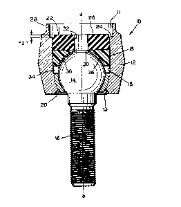
Numéro de la demande Pays / territoire Date
137,393 (Etats-Unis d'Amérique) 1987-12-23

Abrégés

Abrégé anglais


Title
Preloaded Steering Ball Joint Assembly and Method
Abstract of the Invention
A preloaded steering ball joint assembly provides a system
wherein relatively constant torque may be realized over the
useful life of the joint. In a preferred form, the joint
assembly included a housing having a ball socket cavity, and a
ball and a shaft integral with the ball. Top and bottom bearing
seats are disposed for positioning and retaining the ball within
the housing. The bottom seat includes an aperture for permitting
passage of the shaft, while the top seat includes both an
aperture as well as radial passageways for permitting access of
lubricant into a lubricant chamber portion of the socket cavity.
A preferred method of manufacture includes insert molding an
elastomer disc over the top bearing seat by a pre-measured amount
of overfill, then after its formation compressing the elastomer
dics by means of a second disc made of metal by peening the
latter metallic disc over the elastomer disc. The metallic disc
is utilized to compress the predetermined "overfill" of
elastomer, which provides a mechanism by which consistency of
torque preload may be achieved in spite of tolerance variations
in part dimensions. Also, the top seat includes a barrier lip
which extends circumferentially about its upper surface for
preventing leakage of molten elastomer into the lubricant chamber
during the insert molding process.

Revendications

Note : Les revendications sont présentées dans la langue officielle dans laquelle elles ont été soumises.


THE EMBODIMENTS OF THE INVENTION IN WHICH AN EXCLUSIVE
PROPERTY OR PRIVILEGE IS CLAIMED ARE DEFINED AS FOLLOWS:
1. In a preloaded ball joint assembly adapted for use in a
vehicular steering link, said joint assembly including a ball and
a shaft integrally fixed to said ball, a ball housing defining a
longitudinal axis, said housing having first and second openings
aligned with said axis, said first opening containing a
circumferential housing lip, said first opening also containing
an internal circumferentially extending shoulder adjacent said
lip, said second opening defining a passageway for said shaft,
said housing defining an internal ball socket cavity containing
first and second opposed bearing seats positioned within said
cavity against said ball, said seats defining a lubrication
chamber therebetween and about said ball, each bearing seat
comprising a semi-spherical member formed of a low surface
friction material, said second bearing seat containing an opening
for passage of said shaft, said second bearing seat being
positioned against said second opening of said housing to
accommodate said shaft; an improvement comprising said ball
socket cavity containing a compressed elastomer disc juxtaposed
against a metal disc, said elastomer disc being urged against the
first bearing seat by said metal disc, said metal disc retained
tightly against said compressed elastomer disc by said
circumferential housing lip, said first bearing seat including a
circumferential barrier lip dimensioned for an interference fit
with said ball socket cavity, whereby during insert molding of
said elastomer disc, said barrier lip is effective to prevent
- 8 -

pressurized intrusion of molten elastomer into said lubrication
chamber.
2. The preloaded ball joint assembly of claim 1 wherein
said barrier lip defines a member which extends angularly
outwardly in a direction toward said elastomer disc.
3. The preloaded ball joint assembly of claim 2 wherein
said first bearing seat is formed of a polyacetal material.
4. The preloaded ball joint assembly of claim 3 further
comprising a pair of lubrication channels oriented along said
longitudinal axis of said housing, one channel extending through
said elastomer disc and the second channel extending through said
first bearing seat, said channels being in communication with
each other.
5. The preloaded ball joint assembly of claim 4 wherein
said lubrication chamber within said socket cavity is defined by
a circumferentially extending gap about said ball between said
first and second bearing seats.
6. The preloaded ball joint assembly of claim 5 wherein
said first bearing seat comprises a plurality of radially
extending passageways extending between said second lubrication
channel and said lubrication chamber.
7. The preoloaded ball joint assembly of claim 6 wherein
said second seat is formed of a corrosion resistent metallic
material.
8. A method of making a preloaded ball joint assembly
adapted for use in a vehicular steering link, said joint assembly
- 9 -
5.

including a ball, a shaft integrally fixed to said ball, a ball
housing defining a longitudinal axis, said housing having first
and second openings aligned with said axis, the first opening
containing a circumferential housing lip and an internal
circumferentially extending shoulder adjacent said lip, said
second opening defining a passageway for said shaft, said housing
further defining an internal ball socket cavity containing first
and second opposed bearing seats positioned within said cavity
against portions of said ball, each bearing seat comprising a
semi-spherical member of a low surface friction material, said
second of said bearing seats containing an opening for said shaft
and being positioned against said second opening of said housing
to accommodate passage of said shaft, a compressed elastomer disc
being urged tightly against said first bearing seat, a metallic
disc being urged against said elastomer disc and retained tightly
thereagainst by said circumferential lip; said method comprising
the steps of:
a) inserting said second bearing seat containing said opening
within said housing in a manner such that said bearing seat
opening is aligned with said second opening of said housing,
b) inserting said integral ball and shaft member into said
housing by first inserting the shaft portion thereof through
said first and then said second of said housing openings, in
that order,
c) inserting said first bearing seat through said first housing
opening against said ball,
- 10 -

d) insert molding an elastomer disc into said first housing
opening against said first bearing seat by filling said
housing cavity with molten elastomer under pressure to a
predetermined overfill dimension defined by a pre-measured
distance which falls between the extremity of said lip and
said shoulder.
e) installing said metallic disc against said elastomer disc
after the formation of said elastomer disc, and,
f) peening said lip to cause said metallic disc fully engage
said shoulder, thereby compressing said elastomer disc by
said predetermined overfill dimension to effect a desired
preloading of said ball between said bearing seats.
9. The method of claim 8 wherein said predetermined
overfill dimension falls within a range of 30-50 thousandths
of an inch.
10. The method of claim 9 wherein said first bearing seat
is comprised of a polyacetal material.
- 11 -

Description

Note : Les descriptions sont présentées dans la langue officielle dans laquelle elles ont été soumises.


1305200
I1tle
~elo~ded ~teering Ball JO1n~ A~B~ Y ~nd Method
Backaroun~ of the Inventlon
Thl6 lnvention relates to vehi~ular 6teerlng ball ~oint
a~emblies. More particularly, the invention relstes to the
preloading of 6uch a~6emblles for hchieving relatively con6tant
torque6 on the ball ~oint6 over the u6eful live6 of ~uch ~oint6.
A ~a~or requirement of ball ~o$nt6 a6 utllized ln ~teering
links and Bu6pen~lon ~y6tem6 i6 the ~alntainance of a relatively
con6tant rotating torque over the u6eful life of the ~oint.
Normally, a6 the u6eful life progres~e6, the rotating torque
decrea6e6 and teerlng wheel play and 06cillation6 tend to
lncrease to the detriment of vehicular operation. Attempts to
overcome ~uch unde6irable torque loss are numerous. For example,
coil eprlngs have been mployed wlthln the ball socket cavities
of ~olnt a-se~blle~ to urge bearing Dembers con6tantly agalnst
the ball. Iypically, however, the coil pring ha6 a low
compre6s$ve longltudinal la~tic ~odulu6, and the torques
con6equently cannot be ~et ~ufficiently high nough to meet
desired value6. Not only iB there a large reductlon of bearing
contact load under mall ch~nge6 ln part dimen610n6 due to
general wear and abr~6ion, but ln the proces6 of ~anufacture
there often re~ult6 a large deviation ln initially ~et rotating
torque value6. As a result, ball ~oint6 are rarely ~anufactured
with ~ati~factory con6i6tency in preload torque value6.
Moreover, ela6tomer member6 formed under in~ection or insert

1305200
~ol~ing t-chnlgue- hav~ al-o b--n ubetltut-d for coll prlngs to
comp-n-at- for th- ~all oo~pr-~-lv- long~tudlnal la-tlc ~odulu~
of coil prings However, although the u-e o~ la-to~er has
provlded eome i~provement, ~anufacturlng techn$quee for achievlng
consl~tency ln torque value~, r-gardl-s~ of tolerance varlation6
$n part elze6, have not yet been ati6factory
EY~mary of tbe Invent$on
The preloaded eteering ball ~olnt a--embly and ~ethod of the
present lnvent$on provide6 a ey6tem where$n 6 relatively
concictent torque valu- ~ay b- achlev-d ln p$te of fairly wide
tolerance ~ar$ations ln di~en~ion6 of part6 In a preferred
form, a preloaded ball ~oint a-~embly 1- formed whlch utilizes an
~la6tomer di~c formed by an lnsert ~olding proce66, ln6tead of
u6inq a co$1 epr$ng for pr-load$ng the upper or top bear$ng ~eat
of the ~olnt a~embly In a preferr-d form, the ~olnt a66emb1y
lnclude~ ball ocket and lntegral ball-ehaft ~ember6 wlth upper
and lower -~l--pberlcal b-arlng -at6 for po6itioning and
r-talning th- ball within the ock-t cavity However, the top
eeat contain~ an lnt-gral clrcu~ferentlally extending barrier lip
whlch, during the lneert ~oldlng proce66, prevent6 the flow of
~olt-n la~to~er fro~ nterlng the ball eockct cavity The llp
le angled radlally outwardly toward the lasto~er dl-c eo that a6
the preesure lncr-ae-~ durlng the lneQrt ~old$ng proc--s the lip
will expand outwardly again6t the eoc~et cavity wall Ideally,
-- 2 --

130~;200
the ~reat-r th- pr-~-ur- th- gr-at~r th- tend-ncy for the llp to
o acco~mo~ate the pr-~ur- Und-r a pre~-rr-d uethod, the
laetomer i- ln~ert nold-d lnto the cavlty to a pr-deter~ined
overflll dl~en~lon whlch xtendc abov- an lnt-rnal
circu~ferential houlder A Detallic dl~c 1- ln-tall-d atop the
ela6tomer disc to conpre66 the la6tomer dl-c agaln6t the top
eat a p-Qnlng proce~B i- utlllz-d to force the ~etalllc dlec
downwardly o a~ to cauee the dl-c to botto~ agaln6t the ~houlder
and to thereby compr~s6 the la~toner by the pr-deter~ined
dlnenelon to ff-ct d-elr-d torgue preload of the ball between
the bearing eat6
~ Brlef De6crlDtlon of the Drawinae
Flgure 1 1- a cro~6 ~ectlonal view of a preferred e~bodiment
of the ~teering ball ~oint as~embly of the pre6ent inventlon,
~hown durlng one tage Or ite ~anufacturlng proce66
Flgure 2 le a cro-e ectlonal lde vlew of the top bearing
eat ln the mbodl~ent Or Flgure 1
Figure 3 i- an nlarged view Or a circled portlon "A" of
Flgure 2
Figure 4 ie a bottom face view of the top bearing 6eat,
vlewed along llne~ 4-4 of Figure 2
Flgure S 1~ a cross eectlonal vlew of a completed teering
ball ~olnt a-~embly con~tructed ln accordance ~lth a preferred
proc-es Or the pr--ent lnventlon, hown wlth tolerance varlat~on6

- 130S200
of a-~e~bly part- at a ~axl~u~ accumulatlon
Flgure 6 1- a compl-t-d a-~-mbly vl-w l~llar to that of
Flgur~ 5, xc-pt that tol-ranc- varlatlon~ of ~-~e~bly partc are
at their ninlmu~ accu~ulatlon valu-
~etalled Descrlotlon of a Preferred Embodlment
Ref-rrlng lnltlally to F~gure 1, a partially co~pleted ball
~olnt a~embly ~0 describ-6 a longltudlnal axl~ ~a-a~ about whlch
a cyllndrical houslng 12 defines upper and lower openlng6 11 and
13, r--p-ctlvely ~he hou-lng 1~ adapted for contalnment and
dynamlc r-ten-lon of a ball 14 whicb ha- an lnt-grally fixed
ehaft 16 xtendlng th-refrom The lnt-rlor of the hou6ing 12
deflne6 a ball ocket cavlty lS whlch contaln~ an upper or top
bearing ~cat 18 and an oppo~ed lower or bottom bearing ~eat 20
Each eat d-flne6 a ceml-cpberical m-mb~r adapt-d to oppo6ingly
ceat the ball 14 wlthln th- hou~lng 12, a~ hown
For purpo~-- Or pr-loadlng the ball 14 between the palr of
b-arlng ceat~ 18 and 20, an lactomer dl-c 22 1~ ~uxtaposed under
forc- agalnct the top b arlng eeat 18 In the lnventlon a5
d-~crlbed her-ln, the la6tomer dl~c 1~ forned by an ln6ert
moldlng proce~6 whlch 1~ de61gned to accommodate a varlatlon of
tolexance ln dl-enslon6 of the housing, ball, and bearing
me~ber~ ~he invention provides a ~ethod whereln molten
la-tomer 1B in~ert molded lnto that portlon of th- cavity 15
whlch 1~ above the top b-arlng c-at 18 by an amount which
- 4 -

~305200
~lightly ov~rfill- a elrcum~-r-ntlal ~houlder 24 wlthin the
eavlty Henc-, the top Or th~ di-c 26 upon eo~pl-tlon of the
lncert ~olding proce~ will be po61tioned ~bo~- the houlder 24
by a earefully pr~deter~ined amount of la6tomer, indlcnted as
n Z ~I in Figure l
Referring now to Figuree 5 ~nd 6, a co~pleted ball ~oint
~esembly 50 is 6hown whlch include~ a ~etallic disc 44
Referring ~omentarily back to Figure l, lt will be een that a
elreumferentlal elosure lip 28 whieh define6 the extremity of the
upper opening ll of the h4using 12 will, in the final eompleted
~ssembly 50, be peened over the d~c 44 to thereby eompres6 the
ela6tomer disc 22 by the a~ount egual to the ~ZH overfill
dimen6ion The dge6 of the di6c 44 wlll fully ngage the
ehoulder 24 upon the peenlng of the elo6ure lip 28 down over the
di6c
A ~aximum tolerance eondition i~ hown in Figure 5 Those
~ill-d in the art will appreciate that thi~ eonditlon will
produee the largest pos~ible ~iec thiekne66, repre6ented aB n X~l.
By eontra~t, Figure 6 ehowe ~ eompl-ted a-~e~bly 50 ln whieh the
toleranee varlation brlnge about the ~lnlnum ela6tomer disc
thlekne~6, repre6ented a6 ~y" In the embodiment6 of Flgures 5
and 6, the difference in the ~x" and ~y" dimension6, that i6, "x"
~inu~ "y", wa~ in the range of 70-80 thousandths of an inch,
while the ~z" dimen6ion wa6 approxi~ately 40 thoueandths of an
ineh The ~z" dimension reflect6 the amount of ov~rfill which
for preload torgue eonei~teney would be a eonstant value in a

given ball ~olnt a--embly na~Qc~ur~ng process Moreover, the
~z" dlmen-lon ln t~a pr-~-rr-d practlce o~ the ln~-ntlon wlll
vary only by one plu~ or alnu~ flv- thou~andth- of an lnch In
the mbod$~ent her~ln de~crlbed, preload pr-~ure range~ fell
- between 15 to S0 lnch-pounds of torque The ela-tomer di~c w~s
lnsert ~olded, and had a duro~eter value of ~pproxl~ately 52
In the preferred form, the top bearlng eat 18 can be formed
eithcr o a polyacetal material or of a teflon fllled plastic,
although other low frlction ~urface ~aterlal~ may be utilized
For example, the bottom eat 20 wa~ of a poll~hed teel for
rea~ons of mlnlmizlng fertillzer corr~61On ln the e~bodi~ent
de~crlbed
R-ferrlng now to Flgure 1, lt will be appr2ciated by those
ekllled ln the art that the ball ~olnt a~6embly of the present
lnvention mu6t be able to receive and to accommodate lubrication
over lt6 useful llfe For thi6 purpo6e, a pair of communicating
lubrlcatlon channel6 30 and 32 xtend through the top bearing
e-at 18 and the la~tomer dl~c 22, respectively (~ee Fig 1)
The channels permlt lubricant entry lnto a ocket cavity
lubrlcatlon or lubrlcant chamber 34, de~lned by the annular
epacing or gap between the upper and lower bearlng eat~ 18 and
A plurality of radlal lubrication pa66ageway6 36 extends
'~through the bottom face 38 of the top bearing seat 18 (Fig 4) to
allow pas6age of lubrlcant from the channel6 32 and 30 into the

~305200
c~a~ber 34 A6 ~pp~r-nt in Flgur- 1, th- pa~c~gew~ye 36 are
concave to the ext~nt that they follow the urface contour of the
ball 14
~ eferring to Figure6 2-4, it will ~l~o bQ ~pprec~ated by
tho6e akilled in the art that the top bearing e~t 18 include6
another feature which wlll avoid entry of molten elasto~er lnto
the s~cket cham~er 34 durlng insert moldlng of the ela6tomer di~c
22 Thu6, the top bearing ~eat lB ~ontaln6 ~ circu~ferent~ally
extending barrier lip ~0 ~ore clearly ~een ln the enlarged view
of Figure 3 ~he llp includeE an angled ~idewall 42 which
extend6 in ~ direction toward the ela6tomer disc 22, ~nd operates
to in~ure that the llp ~0 will, under pre66ure of the ~olten
elastomer, ~xpand radially outwardly ~gainst the intern~l wall of
the ball ocket cavity 15
Finally, lt will be further appreciated by those 6killed ln
the art that any die ~none iB hown) used for the incert molding
proces6 will prefer~bly define a ~plug~ portlon, which during the
ln~ert ~olding proces6 will xtend down lnto the lubrication
channel 30 in the top bearing ~eat and ~gain~t t~e top of the
ball 14 ln order to ~eep the flnlshed laetomer dl6c from
plugging the channel 30 8uch plug portlon of the die will aleo
have the effect of for~ing the lubrication channel 32 in the
ela6tomer di~c 22 during the insert molding proce66
Although only one preferred embodiment ha6 been detailed and
de6cribed herein, the following claims envi~ion nu~erou6 other
c~bodiments which will fall within the 6pirit and cope thereof
- 7 -

Dessin représentatif
Une figure unique qui représente un dessin illustrant l'invention.
États administratifs

2024-08-01 : Dans le cadre de la transition vers les Brevets de nouvelle génération (BNG), la base de données sur les brevets canadiens (BDBC) contient désormais un Historique d'événement plus détaillé, qui reproduit le Journal des événements de notre nouvelle solution interne.

Veuillez noter que les événements débutant par « Inactive : » se réfèrent à des événements qui ne sont plus utilisés dans notre nouvelle solution interne.

Pour une meilleure compréhension de l'état de la demande ou brevet qui figure sur cette page, la rubrique Mise en garde , et les descriptions de Brevet , Historique d'événement , Taxes périodiques et Historique des paiements devraient être consultées.

Historique d'événement

Description Date
Inactive : Périmé (brevet sous l'ancienne loi) date de péremption possible la plus tardive 2009-07-14
Inactive : CIB de MCD 2006-03-11
Lettre envoyée 2006-02-01
Accordé par délivrance 1992-07-14

Historique d'abandonnement

Il n'y a pas d'historique d'abandonnement

Titulaires au dossier

Les titulaires actuels et antérieures au dossier sont affichés en ordre alphabétique.

Titulaires actuels au dossier
AFFINIA CANADA CORP.
Titulaires antérieures au dossier
KARLE O. KERN
Les propriétaires antérieurs qui ne figurent pas dans la liste des « Propriétaires au dossier » apparaîtront dans d'autres documents au dossier.
Documents

Pour visionner les fichiers sélectionnés, entrer le code reCAPTCHA :


Pour visualiser une image, cliquer sur un lien dans la colonne description du document. Pour télécharger l'image (les images), cliquer l'une ou plusieurs cases à cocher dans la première colonne et ensuite cliquer sur le bouton "Télécharger sélection en format PDF (archive Zip)" ou le bouton "Télécharger sélection (en un fichier PDF fusionné)".

Liste des documents de brevet publiés et non publiés sur la BDBC .

Si vous avez des difficultés à accéder au contenu, veuillez communiquer avec le Centre de services à la clientèle au 1-866-997-1936, ou envoyer un courriel au Centre de service à la clientèle de l'OPIC.


Description du
Document 
Date
(aaaa-mm-jj) 
Nombre de pages   Taille de l'image (Ko) 
Abrégé 1993-11-01 1 29
Revendications 1993-11-01 4 116
Dessins 1993-11-01 1 38
Description 1993-11-01 7 211
Dessin représentatif 2001-11-29 1 12
Courtoisie - Certificat d'enregistrement (document(s) connexe(s)) 2006-01-31 1 105
Correspondance 2005-12-13 4 101
Taxes 1994-06-16 1 72
Taxes 1996-06-19 1 69
Taxes 1995-06-20 1 66