Language selection

Search

Patent 1305361 Summary

Third-party information liability

Some of the information on this Web page has been provided by external sources. The Government of Canada is not responsible for the accuracy, reliability or currency of the information supplied by external sources. Users wishing to rely upon this information should consult directly with the source of the information. Content provided by external sources is not subject to official languages, privacy and accessibility requirements.

Claims and Abstract availability

Any discrepancies in the text and image of the Claims and Abstract are due to differing posting times. Text of the Claims and Abstract are posted:

  • At the time the application is open to public inspection;
  • At the time of issue of the patent (grant).
(12) Patent: (11) CA 1305361
(21) Application Number: 1305361
(54) English Title: FRICTION CASTING WITH POLYMER COVER
(54) French Title: PATIN STABILISATEUR A REVETEMENT POLYMERE
Status: Term Expired - Post Grant
Bibliographic Data
(51) International Patent Classification (IPC):
  • B60F 3/00 (2006.01)
  • B61F 5/12 (2006.01)
  • B61F 5/32 (2006.01)
(72) Inventors :
  • EUNGARD, WILLIAM C. (United States of America)
(73) Owners :
  • STANDARD CAR TRUCK COMPANY
(71) Applicants :
  • STANDARD CAR TRUCK COMPANY (United States of America)
(74) Agent: RICHES, MCKENZIE & HERBERT LLP
(74) Associate agent:
(45) Issued: 1992-07-21
(22) Filed Date: 1989-05-03
Availability of licence: N/A
Dedicated to the Public: N/A
(25) Language of filing: English

Patent Cooperation Treaty (PCT): No

(30) Application Priority Data:
Application No. Country/Territory Date
208,596 (United States of America) 1988-06-20

Abstracts

English Abstract


FRICTION CASTING WITH POLYMER COVER
Abstract of the Disclosure
A friction wedge for use in a railroad car truck
bolster pocket which has a slanted rear wall and adjoining side
walls perpendicular thereto, one surface thereof adapted to bear
against a portion of a car truck side frame and a slanted surface
and adjoining sides adapted to bear against the slanted rear wall
and adjoining side walls of the bolster pocket. The friction
wedge includes a metal body and a polymer cover providing the
slanted surface and adjoining sides, with the polymer cover being
formed in a plurality of sections movable relative to each other
and the metal body such that, during use, the polymer sections
may move into contact with the pocket rear wall and adjoining
side walls.


Claims

Note: Claims are shown in the official language in which they were submitted.

The embodiments of the invention in which an exclusive
property or privilege is claimed are defined as follows:
1. A friction wedge for use in a railroad car truck
bolster pocket having a slanted rear wall and adjoining side
walls generally perpendicular thereto, said friction wedge
including a metal body and a polymer cover formed of a material
having a low coefficient of friction, the metal body having a
surface thereof bearing against a portion of a car truck side
frame, said polymer cover having a slanted surface and adjoining
sides bearing against the slanted rear wall and adjoining side
walls of the bolster pocket, said metal body having a wedge-
shaped cover support which conforms to the interior of said
polymer cover whereby said wedge-shaped cover support will cause
said polymer cover to bear against the bolster pocket rear wall
and adjoining side walls during use of the friction wedge.
2. The friction wedge of claim 1 further characterized
in that said polymer cover is in a plurality of sections movable
relative to each other and to the metal body such that during use
said sections may spread apart by the action of the wedge-shaped
cover support to bear against the bolster pocket rear wall and
adjoining side walls.
3. The friction wedge of claim 2 further characterized
in that there are two symmetrical polymer sections.
4. The friction wedge of claim 1 further characterized
in that said metal body includes a side frame wall, a bottom and
a wedge-shaped cover support integral therewith.
5. The friction wedge of claim 4 further characterized
in that said wedge-shaped cover support includes a slanted
surface, side frame wall, and bottom of said metal body.
6. The friction wedge of claim 4 further characterized
in that said wedge-shaped cover support has a slanted curved
profile joining the side frame wall and bottom of the metal body.
-7-

7. The friction wedge of claim 6 further characterized
in that said curved profile cover support has a tangent portion
generally parallel to and facing the slanted rear wall of the
bolster pocket.
8. The friction wedge of claim 4 further characterized
in that said polymer cover is a single flexible element such
that, during use, the cover may be spread by the wedge cover
support so the cover may bear against the bolster pocket rear
wall and adjoining side walls.
- 8 -

Description

Note: Descriptions are shown in the official language in which they were submitted.


Summar~ o~ the Invention
The present invention relates to friction wedges for
use in the pocket of a railroad car truck bolster and in par-
ticular to such a friction wedge having a metal body and polymer
cover for those surfaces engaging the bolster pocket.
Another purpose is a friction wedge of the type
described in which a sectioned polymer cover comprise~ those
portions of the friction wedge which are in contact with the
bolster pocket, with the sections being self adjusting, during
use, into full contact with the bolster pocket slanted rear wall
and adjoining side walls.
Another purpose is a friction wedge of the type
described in which the polymer cover is formed of a high density,
linear polyethylene of very hi.gh molecular weight (UHMW polymer)
having a very low static and kinematic coefficient of friction
against a metal surface.
Another purpose is a friction wedge of the type
described having a polymer cover to protect the slanted rear
wall and side walls of the bolster pocket from wear.
Another purpose is a friction wedge of the type
described utilizing a sectioned polymer cover which es~entially
prevents relative lateral movement between the friction wedge
and the adjoining surfaces of the bolster pocket.
Other purposes will appear in the ensuing specifica-
tion, drawings and claims.
Brief Description of the Drawings
The invention is illustrated diagrammatically in the
following drawings wherein:
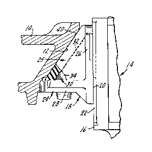
Figure 1 is a bottom plan view of a portion of a
railroad car truck bolster and a friction wedge,
Figure 2 is a section taken substantially along plane
2-2 of Figure 1,

5;~
Figure 3 is a left side view of the friction wedge
of Figure 2,
Figure 4 is an isometric view of the friction wedge
and one section of the polymer cover,
Figure 5 is an isometric view, similar to Figure 4,
showing a modified form of the invention, and
Figure 6 is an isometric view of the friction wedge
showing a singular polymer cover.
Description of the Preferred Embodiment
It has long been conventional in railroad car trucks
to position a friction wedge in a bolster pocket to dampen
movement between the bolster and the side frame. To prevent
wear to the bolster pocket, which is conventionally formed of
a relatively soft steel casting, it has been conventional to
position a hardened steel wear plate along the slanted wall
of the bolster pocke~. A wear plate is also positioned on the
vertical column of the side frame, with the dampening wedge
being positioned between and bearing against both wear plates.
It has been noted, particularly in high mileage, high
utilization railroad cars, such as those on unit coal trains,
that there is substantial wear on the bolster pocket side walls,
particularly the outboard side wall. Such wear on the bolster
pocket may be due to the phenomenon known in the art as ~hunt-
ing," to the rock and roll action of a freight car on rough
track, and to the action of the truck passing through a switch
wherein the bolster may move laterally relative to the side
frames causing a wear and impact-type of reaction between the
bolster pocket and the friction wedge positioned therein. The
basic friction wedge as described herein has long been known
in the art and in the last several years various attempts have
been made to protect the bolster pocket from friction wedge wear,
for example as illustrated in U. S. Patent 4,426,934, assigned

to the assignee of the present application and in U. S. Patent
Re. 31,988.
The present invention provides a protective cover for
the friction wedge in the form of a U~W polymer having a low
coefficient of friction which eliminates the need for a bolster
pocket wear plate and provides protection for both the slanted
rear wall and side walls of the bolster pocket.
U. S. Patent 3,851,595, also assigned to the assignee
of the present application, illustrates the conventional railroad
car truck side frame, the springs supporting the bolster within
the side frame window and the friction wedge and its supporting
spring. In the present application only the bolster, bolster
pocket and a portion of the side frame column are illustrated
along with the improved friction wedge which is the subject of
the present application.
In Figure 1, the bolster is indicated at 10 and the
bolster pocket 11 has a slanted rear wall 12 and side walls 13.
Facing bolster lO is a side frame, indicated generally at 14,
having a side frame column 16 which, along with the bolster
pocket, confine a friction wedge indicated generally at 18.
Friction wedge 18, which will be formed of a conven~
tional cast iron, ha~ a generally vertical wear surface 20 which
faces a side frame wear plate 22.
Friction wedge 18 is formed of a metal body 24 and a
cover 25 formed of a UHMW polymer which has a very low coeffi-
cient of friction. Body 24 includes a vertical side frame wall
26 which faces side frame column 16 and a horizontal bottom 28
containing a spring seat which are integrally formed together
with a wedge-shaped cover support 30. Cover support 30 has
a rearwardly facing slanted surface 32 and triangular shaped
surfaces 34 which join slanted surface 32, bottom 28 and side
frame wall 26.

Cover 25 is preferably formed in a plurality of
sections and, as shown herein, there are two such sections which
are symmetrical. The sectioned cover includes sides 36 and 38
and a slanted surface 40 which, when the friction wedge is
positioned within the bolster pocket, will bear against the rear
slanted wall 12 of the bolster. The inside of cover 25 will
have a configuration to match and conform to the cover support
and particularly walls 32 and 34, as well as that portion 42 of
side frame wall 26 and that portion 41 of the bottom 28 which
forms a support for the cover. Thus, the interior of the cover
and the exterior of the friction wedge metal body will conform
50 that together the elements provide the customary shape for a
friction wedge and one which may be retrofitted into any current
bolster pocket.
The wedge-shaped support for the polymer cover will
tend to force the two sections apart during use so that they
will completely fill the bolster pocket and the sides 36 and
38 of the cover will bear against the side walls of the bolster
pocket. In this way, the sectioned cover can accomodate the
bolster pocket casting tolerances or any irregularities in the
bolster pocket surfaces or any misalignment between the side
frame column and the bolster. The cover will insure that the
wedge is correctly positioned within the bolster pocket and in
firm and complete contact with the side frame column, slanted
rear wall of the bolster pocket and the side walls thereof.
There will be little, if any, relative movement between the
friction wedge and the bolster pocket and what movement there
is, since it is relatively free of friction because of ~he low
coefficient of friction of the polymer cover, will cause no wear
on the bolster pocket surfaces.
Although it is preferred that the polymer cover be
sectioned, in some applications a single cover may be acceptable

if it has a degree of flexibility such that it can conform to
the shape of the bolster pocket once it i5 in use.
Figure 5 illustrates a modified form of the invention
in which the wedge shaped cover support has a curved profile 44
rather than flat sides as shown in Figures 1-4. Surface 44 will
have a central tangent portion 46 which is generally parallel
to and facing the slanted rear wall 12 of the bolster pocket.
The interior of cover 48 will have a configuration to match and
conform to the cover support.
Figure 6 illustrates another modified form of the
invention in which a polymer cover 49 is a single element xather
than the two symmetrical sections shown in Figures 1-5. The
inside of cover 49 will have a configuration to match and conform
to the wedge support.
Whereas the preferred form of the invention has been
shown and described herein, it should be realized that there may
be many modifications, substitutions and alterations thereto.

Representative Drawing
A single figure which represents the drawing illustrating the invention.
Administrative Status

2024-08-01:As part of the Next Generation Patents (NGP) transition, the Canadian Patents Database (CPD) now contains a more detailed Event History, which replicates the Event Log of our new back-office solution.

Please note that "Inactive:" events refers to events no longer in use in our new back-office solution.

For a clearer understanding of the status of the application/patent presented on this page, the site Disclaimer , as well as the definitions for Patent , Event History , Maintenance Fee  and Payment History  should be consulted.

Event History

Description Date
Inactive: Expired (old Act Patent) latest possible expiry date 2009-07-21
Inactive: IPC from MCD 2006-03-11
Inactive: Entity size changed 1998-06-25
Grant by Issuance 1992-07-21

Abandonment History

There is no abandonment history.

Owners on Record

Note: Records showing the ownership history in alphabetical order.

Current Owners on Record
STANDARD CAR TRUCK COMPANY
Past Owners on Record
WILLIAM C. EUNGARD
Past Owners that do not appear in the "Owners on Record" listing will appear in other documentation within the application.
Documents

To view selected files, please enter reCAPTCHA code :


To view images, click a link in the Document Description column. To download the documents, select one or more checkboxes in the first column and then click the "Download Selected in PDF format (Zip Archive)" or the "Download Selected as Single PDF" button.

List of published and non-published patent-specific documents on the CPD .

If you have any difficulty accessing content, you can call the Client Service Centre at 1-866-997-1936 or send them an e-mail at CIPO Client Service Centre.


Document
Description 
Date
(yyyy-mm-dd) 
Number of pages   Size of Image (KB) 
Cover Page 1993-11-04 1 11
Abstract 1993-11-04 1 19
Claims 1993-11-04 2 56
Drawings 1993-11-04 3 61
Descriptions 1993-11-04 5 182
Representative drawing 2001-11-30 1 9
Fees 2003-06-09 1 34
Fees 2001-06-13 1 36
Fees 2002-06-27 1 35
Fees 1997-06-27 1 39
Fees 1998-06-15 1 46
Fees 1999-06-11 1 37
Fees 2000-07-07 1 36
Fees 1995-06-20 1 43
Fees 1996-06-07 1 43
Fees 1994-06-15 1 47