Sélection de la langue

Search

Sommaire du brevet 1305361 

Énoncé de désistement de responsabilité concernant l'information provenant de tiers

Une partie des informations de ce site Web a été fournie par des sources externes. Le gouvernement du Canada n'assume aucune responsabilité concernant la précision, l'actualité ou la fiabilité des informations fournies par les sources externes. Les utilisateurs qui désirent employer cette information devraient consulter directement la source des informations. Le contenu fourni par les sources externes n'est pas assujetti aux exigences sur les langues officielles, la protection des renseignements personnels et l'accessibilité.

Disponibilité de l'Abrégé et des Revendications

L'apparition de différences dans le texte et l'image des Revendications et de l'Abrégé dépend du moment auquel le document est publié. Les textes des Revendications et de l'Abrégé sont affichés :

  • lorsque la demande peut être examinée par le public;
  • lorsque le brevet est émis (délivrance).
(12) Brevet: (11) CA 1305361
(21) Numéro de la demande: 1305361
(54) Titre français: PATIN STABILISATEUR A REVETEMENT POLYMERE
(54) Titre anglais: FRICTION CASTING WITH POLYMER COVER
Statut: Durée expirée - après l'octroi
Données bibliographiques
(51) Classification internationale des brevets (CIB):
  • B60F 3/00 (2006.01)
  • B61F 5/12 (2006.01)
  • B61F 5/32 (2006.01)
(72) Inventeurs :
  • EUNGARD, WILLIAM C. (Etats-Unis d'Amérique)
(73) Titulaires :
  • STANDARD CAR TRUCK COMPANY
(71) Demandeurs :
  • STANDARD CAR TRUCK COMPANY (Etats-Unis d'Amérique)
(74) Agent: RICHES, MCKENZIE & HERBERT LLP
(74) Co-agent:
(45) Délivré: 1992-07-21
(22) Date de dépôt: 1989-05-03
Licence disponible: S.O.
Cédé au domaine public: S.O.
(25) Langue des documents déposés: Anglais

Traité de coopération en matière de brevets (PCT): Non

(30) Données de priorité de la demande:
Numéro de la demande Pays / territoire Date
208,596 (Etats-Unis d'Amérique) 1988-06-20

Abrégés

Abrégé anglais


FRICTION CASTING WITH POLYMER COVER
Abstract of the Disclosure
A friction wedge for use in a railroad car truck
bolster pocket which has a slanted rear wall and adjoining side
walls perpendicular thereto, one surface thereof adapted to bear
against a portion of a car truck side frame and a slanted surface
and adjoining sides adapted to bear against the slanted rear wall
and adjoining side walls of the bolster pocket. The friction
wedge includes a metal body and a polymer cover providing the
slanted surface and adjoining sides, with the polymer cover being
formed in a plurality of sections movable relative to each other
and the metal body such that, during use, the polymer sections
may move into contact with the pocket rear wall and adjoining
side walls.

Revendications

Note : Les revendications sont présentées dans la langue officielle dans laquelle elles ont été soumises.


The embodiments of the invention in which an exclusive
property or privilege is claimed are defined as follows:
1. A friction wedge for use in a railroad car truck
bolster pocket having a slanted rear wall and adjoining side
walls generally perpendicular thereto, said friction wedge
including a metal body and a polymer cover formed of a material
having a low coefficient of friction, the metal body having a
surface thereof bearing against a portion of a car truck side
frame, said polymer cover having a slanted surface and adjoining
sides bearing against the slanted rear wall and adjoining side
walls of the bolster pocket, said metal body having a wedge-
shaped cover support which conforms to the interior of said
polymer cover whereby said wedge-shaped cover support will cause
said polymer cover to bear against the bolster pocket rear wall
and adjoining side walls during use of the friction wedge.
2. The friction wedge of claim 1 further characterized
in that said polymer cover is in a plurality of sections movable
relative to each other and to the metal body such that during use
said sections may spread apart by the action of the wedge-shaped
cover support to bear against the bolster pocket rear wall and
adjoining side walls.
3. The friction wedge of claim 2 further characterized
in that there are two symmetrical polymer sections.
4. The friction wedge of claim 1 further characterized
in that said metal body includes a side frame wall, a bottom and
a wedge-shaped cover support integral therewith.
5. The friction wedge of claim 4 further characterized
in that said wedge-shaped cover support includes a slanted
surface, side frame wall, and bottom of said metal body.
6. The friction wedge of claim 4 further characterized
in that said wedge-shaped cover support has a slanted curved
profile joining the side frame wall and bottom of the metal body.
-7-

7. The friction wedge of claim 6 further characterized
in that said curved profile cover support has a tangent portion
generally parallel to and facing the slanted rear wall of the
bolster pocket.
8. The friction wedge of claim 4 further characterized
in that said polymer cover is a single flexible element such
that, during use, the cover may be spread by the wedge cover
support so the cover may bear against the bolster pocket rear
wall and adjoining side walls.
- 8 -

Description

Note : Les descriptions sont présentées dans la langue officielle dans laquelle elles ont été soumises.

Summar~ o~ the Invention
The present invention relates to friction wedges for
use in the pocket of a railroad car truck bolster and in par-
ticular to such a friction wedge having a metal body and polymer
cover for those surfaces engaging the bolster pocket.
Another purpose is a friction wedge of the type
described in which a sectioned polymer cover comprise~ those
portions of the friction wedge which are in contact with the
bolster pocket, with the sections being self adjusting, during
use, into full contact with the bolster pocket slanted rear wall
and adjoining side walls.
Another purpose is a friction wedge of the type
described in which the polymer cover is formed of a high density,
linear polyethylene of very hi.gh molecular weight (UHMW polymer)
having a very low static and kinematic coefficient of friction
against a metal surface.
Another purpose is a friction wedge of the type
described having a polymer cover to protect the slanted rear
wall and side walls of the bolster pocket from wear.
Another purpose is a friction wedge of the type
described utilizing a sectioned polymer cover which es~entially
prevents relative lateral movement between the friction wedge
and the adjoining surfaces of the bolster pocket.
Other purposes will appear in the ensuing specifica-
tion, drawings and claims.
Brief Description of the Drawings
The invention is illustrated diagrammatically in the
following drawings wherein:
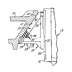
Figure 1 is a bottom plan view of a portion of a
railroad car truck bolster and a friction wedge,
Figure 2 is a section taken substantially along plane
2-2 of Figure 1,

5;~
Figure 3 is a left side view of the friction wedge
of Figure 2,
Figure 4 is an isometric view of the friction wedge
and one section of the polymer cover,
Figure 5 is an isometric view, similar to Figure 4,
showing a modified form of the invention, and
Figure 6 is an isometric view of the friction wedge
showing a singular polymer cover.
Description of the Preferred Embodiment
It has long been conventional in railroad car trucks
to position a friction wedge in a bolster pocket to dampen
movement between the bolster and the side frame. To prevent
wear to the bolster pocket, which is conventionally formed of
a relatively soft steel casting, it has been conventional to
position a hardened steel wear plate along the slanted wall
of the bolster pocke~. A wear plate is also positioned on the
vertical column of the side frame, with the dampening wedge
being positioned between and bearing against both wear plates.
It has been noted, particularly in high mileage, high
utilization railroad cars, such as those on unit coal trains,
that there is substantial wear on the bolster pocket side walls,
particularly the outboard side wall. Such wear on the bolster
pocket may be due to the phenomenon known in the art as ~hunt-
ing," to the rock and roll action of a freight car on rough
track, and to the action of the truck passing through a switch
wherein the bolster may move laterally relative to the side
frames causing a wear and impact-type of reaction between the
bolster pocket and the friction wedge positioned therein. The
basic friction wedge as described herein has long been known
in the art and in the last several years various attempts have
been made to protect the bolster pocket from friction wedge wear,
for example as illustrated in U. S. Patent 4,426,934, assigned

to the assignee of the present application and in U. S. Patent
Re. 31,988.
The present invention provides a protective cover for
the friction wedge in the form of a U~W polymer having a low
coefficient of friction which eliminates the need for a bolster
pocket wear plate and provides protection for both the slanted
rear wall and side walls of the bolster pocket.
U. S. Patent 3,851,595, also assigned to the assignee
of the present application, illustrates the conventional railroad
car truck side frame, the springs supporting the bolster within
the side frame window and the friction wedge and its supporting
spring. In the present application only the bolster, bolster
pocket and a portion of the side frame column are illustrated
along with the improved friction wedge which is the subject of
the present application.
In Figure 1, the bolster is indicated at 10 and the
bolster pocket 11 has a slanted rear wall 12 and side walls 13.
Facing bolster lO is a side frame, indicated generally at 14,
having a side frame column 16 which, along with the bolster
pocket, confine a friction wedge indicated generally at 18.
Friction wedge 18, which will be formed of a conven~
tional cast iron, ha~ a generally vertical wear surface 20 which
faces a side frame wear plate 22.
Friction wedge 18 is formed of a metal body 24 and a
cover 25 formed of a UHMW polymer which has a very low coeffi-
cient of friction. Body 24 includes a vertical side frame wall
26 which faces side frame column 16 and a horizontal bottom 28
containing a spring seat which are integrally formed together
with a wedge-shaped cover support 30. Cover support 30 has
a rearwardly facing slanted surface 32 and triangular shaped
surfaces 34 which join slanted surface 32, bottom 28 and side
frame wall 26.

Cover 25 is preferably formed in a plurality of
sections and, as shown herein, there are two such sections which
are symmetrical. The sectioned cover includes sides 36 and 38
and a slanted surface 40 which, when the friction wedge is
positioned within the bolster pocket, will bear against the rear
slanted wall 12 of the bolster. The inside of cover 25 will
have a configuration to match and conform to the cover support
and particularly walls 32 and 34, as well as that portion 42 of
side frame wall 26 and that portion 41 of the bottom 28 which
forms a support for the cover. Thus, the interior of the cover
and the exterior of the friction wedge metal body will conform
50 that together the elements provide the customary shape for a
friction wedge and one which may be retrofitted into any current
bolster pocket.
The wedge-shaped support for the polymer cover will
tend to force the two sections apart during use so that they
will completely fill the bolster pocket and the sides 36 and
38 of the cover will bear against the side walls of the bolster
pocket. In this way, the sectioned cover can accomodate the
bolster pocket casting tolerances or any irregularities in the
bolster pocket surfaces or any misalignment between the side
frame column and the bolster. The cover will insure that the
wedge is correctly positioned within the bolster pocket and in
firm and complete contact with the side frame column, slanted
rear wall of the bolster pocket and the side walls thereof.
There will be little, if any, relative movement between the
friction wedge and the bolster pocket and what movement there
is, since it is relatively free of friction because of ~he low
coefficient of friction of the polymer cover, will cause no wear
on the bolster pocket surfaces.
Although it is preferred that the polymer cover be
sectioned, in some applications a single cover may be acceptable

if it has a degree of flexibility such that it can conform to
the shape of the bolster pocket once it i5 in use.
Figure 5 illustrates a modified form of the invention
in which the wedge shaped cover support has a curved profile 44
rather than flat sides as shown in Figures 1-4. Surface 44 will
have a central tangent portion 46 which is generally parallel
to and facing the slanted rear wall 12 of the bolster pocket.
The interior of cover 48 will have a configuration to match and
conform to the cover support.
Figure 6 illustrates another modified form of the
invention in which a polymer cover 49 is a single element xather
than the two symmetrical sections shown in Figures 1-5. The
inside of cover 49 will have a configuration to match and conform
to the wedge support.
Whereas the preferred form of the invention has been
shown and described herein, it should be realized that there may
be many modifications, substitutions and alterations thereto.

Dessin représentatif
Une figure unique qui représente un dessin illustrant l'invention.
États administratifs

2024-08-01 : Dans le cadre de la transition vers les Brevets de nouvelle génération (BNG), la base de données sur les brevets canadiens (BDBC) contient désormais un Historique d'événement plus détaillé, qui reproduit le Journal des événements de notre nouvelle solution interne.

Veuillez noter que les événements débutant par « Inactive : » se réfèrent à des événements qui ne sont plus utilisés dans notre nouvelle solution interne.

Pour une meilleure compréhension de l'état de la demande ou brevet qui figure sur cette page, la rubrique Mise en garde , et les descriptions de Brevet , Historique d'événement , Taxes périodiques et Historique des paiements devraient être consultées.

Historique d'événement

Description Date
Inactive : Périmé (brevet sous l'ancienne loi) date de péremption possible la plus tardive 2009-07-21
Inactive : CIB de MCD 2006-03-11
Inactive : Grandeur de l'entité changée 1998-06-25
Accordé par délivrance 1992-07-21

Historique d'abandonnement

Il n'y a pas d'historique d'abandonnement

Titulaires au dossier

Les titulaires actuels et antérieures au dossier sont affichés en ordre alphabétique.

Titulaires actuels au dossier
STANDARD CAR TRUCK COMPANY
Titulaires antérieures au dossier
WILLIAM C. EUNGARD
Les propriétaires antérieurs qui ne figurent pas dans la liste des « Propriétaires au dossier » apparaîtront dans d'autres documents au dossier.
Documents

Pour visionner les fichiers sélectionnés, entrer le code reCAPTCHA :


Pour visualiser une image, cliquer sur un lien dans la colonne description du document. Pour télécharger l'image (les images), cliquer l'une ou plusieurs cases à cocher dans la première colonne et ensuite cliquer sur le bouton "Télécharger sélection en format PDF (archive Zip)" ou le bouton "Télécharger sélection (en un fichier PDF fusionné)".

Liste des documents de brevet publiés et non publiés sur la BDBC .

Si vous avez des difficultés à accéder au contenu, veuillez communiquer avec le Centre de services à la clientèle au 1-866-997-1936, ou envoyer un courriel au Centre de service à la clientèle de l'OPIC.


Description du
Document 
Date
(aaaa-mm-jj) 
Nombre de pages   Taille de l'image (Ko) 
Page couverture 1993-11-04 1 11
Abrégé 1993-11-04 1 19
Revendications 1993-11-04 2 56
Dessins 1993-11-04 3 61
Description 1993-11-04 5 182
Dessin représentatif 2001-11-30 1 9
Taxes 2003-06-09 1 34
Taxes 2001-06-13 1 36
Taxes 2002-06-27 1 35
Taxes 1997-06-27 1 39
Taxes 1998-06-15 1 46
Taxes 1999-06-11 1 37
Taxes 2000-07-07 1 36
Taxes 1995-06-20 1 43
Taxes 1996-06-07 1 43
Taxes 1994-06-15 1 47