Language selection

Search

Patent 1305400 Summary

Third-party information liability

Some of the information on this Web page has been provided by external sources. The Government of Canada is not responsible for the accuracy, reliability or currency of the information supplied by external sources. Users wishing to rely upon this information should consult directly with the source of the information. Content provided by external sources is not subject to official languages, privacy and accessibility requirements.

Claims and Abstract availability

Any discrepancies in the text and image of the Claims and Abstract are due to differing posting times. Text of the Claims and Abstract are posted:

  • At the time the application is open to public inspection;
  • At the time of issue of the patent (grant).
(12) Patent: (11) CA 1305400
(21) Application Number: 1305400
(54) English Title: DEVICE FOR VERTICAL ADJUSTMENT OF ARM SUPPORTS ON CHAIRS, ESPECIALLY WHEEL CHAIRS
(54) French Title: DISPOSITIF DE REGLAGE VERTICAL DES APPUI-BRAS D'UN FAUTEUIL, EN PARTICULIER D'UN FAUTEUIL ROULANT
Status: Expired and beyond the Period of Reversal
Bibliographic Data
(51) International Patent Classification (IPC):
  • A47C 07/54 (2006.01)
  • A61G 05/12 (2006.01)
(72) Inventors :
  • FROYLAND, ARNFINN (Norway)
  • LOHRE, THORBJORN (Norway)
(73) Owners :
  • ARNFINN FROYLAND
  • THORBJORN LOHRE
(71) Applicants :
(74) Agent: SMART & BIGGAR LP
(74) Associate agent:
(45) Issued: 1992-07-21
(22) Filed Date: 1989-06-12
Availability of licence: N/A
Dedicated to the Public: N/A
(25) Language of filing: English

Patent Cooperation Treaty (PCT): No

(30) Application Priority Data:
Application No. Country/Territory Date
882600 (Norway) 1988-06-13
890150 (Norway) 1989-01-13

Abstracts

English Abstract


A b s t r a c t
In a device for vertical adjustment of arm supports on
chairs, especially wheel chairs, each arm support (1) is
carried by a support pipe (2) longitudinally displaceably
arranged in a bore (3') of a part (3) rigidly connected to
the chair frame (1'), the support pipe (2) being lockable to
the chair frame (1',3) in its various positions of
longitudinal displacement. It is aimed at providing a device
of this kind wherein the height adjustment of the arm
support occurs infinitely variably and controlled, and
wherein the height-adjusting device is handy in use. For
this purpose a longitudinally non-displaceable motion screw
is rotationally supported within the support pipe (2), a lug
(5) rigidly connected to the chair frame (1',3) engaging
said motion screw, the latter being adapted to cooperate
with a manually releasable (8) locking device (9, 10) which
in the locking position prevents rotation of the motion
screw (4).
(Figure 1)


Claims

Note: Claims are shown in the official language in which they were submitted.

25871-79
THE EMBODIMENTS OF THE INVENTION IN WHICH AN EXCLUSIVE
PROPERTY OR PRIVILEGE IS CLAIMED ARE DEFINED AS FOLLOWS:
1. A chair having adjustable arm supports, comprising:
a chair frame;
means, fixedly connected to said chair frame, defining a
longitudinal bore;
a support pipe longitudinally displaceable in said bore;
an arm support carried by said support pipe;
said support pipe being adapted to be locked to said chair
frame in various longitudinal positions;
an axially fixed motion screw rotatably supported in said
support pipe;
a lug rigidly connected to said chair frame, said lug
engaging said motion screw between threads thereof;
a manually releasable locking means cooperating with said
motion screw, said locking means preventing rotation of said
motion screw in a locking position thereof
said locking means comprising a longitudinally displaceable
slide disposed within said support pipe, said slide having a
locking cotter at a lower end thereof and an external handle at an
upper end thereof adjacent said arm support, said external handle
being guided in a first slot extending longitudinally in said
support pipe, said locking cotter being adapted to cooperate and
lock into a locking groove formed in an end portion of said motion
screw, said first slot having a length exceeding the depth of
engagement between said locking cotter and said locking groove;
and
a second slot extending longitudinally in said support pipe

6 25871-79
in the area of said lug, the longitudinal length of said second
slot being greater than the desired maximum height adjustment for
said arm support.
2. The chair according to claim 1, further comprising means
for urging said slide downward to a locking position.
3. The chair according to claim 1, wherein said locking
groove has a cross-shaped cross section.
4. The chair according to claim 1, wherein said motion
screw has a non-threaded end portion which faces said slide, a
circumferential second groove, a second lug rigidly connected to
said support pipe and engaging said second groove, thereby
preventing longitudinal displacement but allowing rotation of said
motion screw relative to said support pipe.

Description

Note: Descriptions are shown in the official language in which they were submitted.


:~L3~
1 25871-79
This invention relates to a device for vertical
adjustment of arm supports on chairs, especially wheel chairs,
wherein each arm support is carried by a support pipe
longitudinally displaceably arranged in a bore of a part fixedly
connected to the chair frame, and wherein the support pipe can be
locked to the chair Erame on its various positions of longitudinal
displacement.
In a known device for vertical adjustment of this kind,
each of the support pipes of the arm supports is telescopically
displaceable in a pipe fixedly connected to the chair frame. A
screw bolt serves to lock the telescopically displaceable support
pipe to the frame pipe. Upon adjustment of height, the locking
bolt is unscrewed, whereafter the support pipe is displaced
telescopically in -the frame pipe until one has achieved the
desired adjustment of height oE the arm support. Thereafter, the
locking bolt is tightened again.
This known device for vertical adjustment of arm
supports is cumbersome in use and, moreover, it is often difficult
to obtain an exact adjustment of height.
The object of this invention is to provide a vertical
adjustment device which is handy in use and additionally wherein
it is easy to effect an accurate adjustment of height.
; The invention provides a chair having adjustable arm
supportsl comprising: a chair frame; means, fixedly connected to
said chair frame, defining a longitudinal bore; a support pipe
longitudinally displaceable in said bore; an arm support carried
by said support pipe; said support pipe being adapted to be locked
~ to sald chair frame in various longitudinal positions; an axially
.~ .
~ :
,, .

:~3~S~
- 2 25~71-7g
.Eixed motion screw rotatably supported in said support pipe; a lug
rigidly connected to said chair frame, said lug engaging said
motion screw between threads thereof; a manually releasable
locking means cooperati.ng wi-th said motion screw, said locking
means preventing rota-tion of said motion screw in a locking
position thereof; said locking means comprising a longitudinally
displaceable slide disposed within said support pipe, said slide
having a locking cotter at a lower end thereof and an external
handle at an upper end thereof adjacent said arm support, said
external handle being guided in a first slot extendi.ng
longitudinally in said support pipe, said locking cotter being
adapted to cooperate and lock into a locking groove formed in an
end portion of said motion screw, said first slot having a length
exceeding the depth of engagement between said locking cotter and
said locking groove; and a second slot extending longitudinally in
said support pipe in the area of said lug, the longitudinal length
of said second slot being greater than the desired maximum height
adjustment for said arm support.
Through this rotary mounting of an axially non-
displaceable motion screw in the support pipe a variable adjust-
ment of the vertical position of the arm support is achieved when-
: ever the arm support is raised or lowered. The motion screw also
: ensures a very accurate adjustment of the vertical position of the
: arm support.
An example of the device for vertical adjustment of arm
supports is more fully explained in the following, reference being
,
made to the accompanying drawings, wherein:
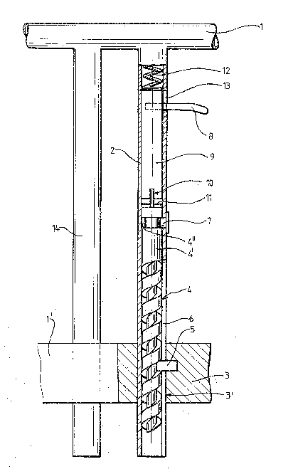
: ~ Figure 1 in side elevation/axial section shows a device
,
!
~, ' ' ~ ' ' ' ~ ,
,' .
~ '
;

13(?S~
2a
for vertical adjustment of arm supports in accordance with the
invention; and
Figure 2 in perspective shows a detail view of the upper
end portion of the motion screw.
.`: ~ :: :
~;:~ : :
,

~ll3~S4Q~;31
In the drawings, reference numeral 1 denotes one of the arm
supports incorporated into a wheel chair frame 1' only shown
partially.
The arm support 1 is carried by a vertical support pipe 2
which is axially displaceably supported in a bore 3l of a
bracket 3 rigidly connected to the chair frame 1' .
Rotationally arranged in the lower portion of the support
pipe 2 is a motion screw 4, the upper portion 4' of which is
formed without screw threads. In between the threads of the
motion screw engages a lug 5 fastened to the bracket 3 and
extending through a longitudinal slot 6 of the support pipe
2. This slot 6 should have a longitudinal extension somewhat
exceeding the desired maximum area of height adjustment for
the arm support 1.
The upper unthreaded portion 4' of the motion screw is
provided with a circumferential groove 4" wherein a lug 7
attached to the support pipe 2 engages. The engagement of
the lug 7 within the circumferential groove 4" of the screw
prevents axial displacement of the screw 4.
A simple handle 8 is rigidly connected to an axially
displaceable locking slide 9 in the support pipe 2, said
locking slide lowermost carrying a locking cotter 10 for
engagement in a preferably cross-shaped groove 11, Figure 2,
formed in the adjacent gable surface of the motion screw.
The locking slide 9 is spring-loaded downwards toward
~locking position, Figure 1, but-the engagement of the
locking cotter 10 within the cross-groove 11 can be released
through moving the handle 8 a short distance upwards in a
slot 13 of the support pipe. Thereby, the locking cotter 10
if lifted clear of the groove 11, whereafter the motion
screw 4 can rotate freely.
,-..

~3(~5~0
Through lifting or lowering the arm support 1 in this
position in order to achieve the desired position of height,
the screw 4 is rotated in the one or other direction, the
stationary lug 5 engaging in between its threads. The
support pipe 2 of the arm support l is thereby displaced
upward or downward until the desired height position of the
arm support 1 is reached. Thereafter, the handle 8 is
released and the spring 12 brings the locking cotter 10 of
the locking slide 9 into engagement within the locking
groove 11 of the screw 4, whereafter the height position of
the arm support is locked.
Through the use of a sufficiently heavy locking slide 9, the
spring may possibly be omitted.
14 denotes a support pipe extending freely through the :l;
bracket 3 and parallel to the support pipe 2.
The arm support height adjusting device according to the
invention is very handy in use. Infinitely variable
adjustment of height is achieved.
Simultaneously, the motion screw offers a small but desired
resistance during the vertical adjustment, which thereby
becomes much more controlled than what previously has been
possible by means of telescopic pipes.
:
:: :
:
, ~
~: ~
.

Representative Drawing
A single figure which represents the drawing illustrating the invention.
Administrative Status

2024-08-01:As part of the Next Generation Patents (NGP) transition, the Canadian Patents Database (CPD) now contains a more detailed Event History, which replicates the Event Log of our new back-office solution.

Please note that "Inactive:" events refers to events no longer in use in our new back-office solution.

For a clearer understanding of the status of the application/patent presented on this page, the site Disclaimer , as well as the definitions for Patent , Event History , Maintenance Fee  and Payment History  should be consulted.

Event History

Description Date
Inactive: Adhoc Request Documented 1996-07-21
Time Limit for Reversal Expired 1996-01-22
Letter Sent 1995-07-21
Grant by Issuance 1992-07-21

Abandonment History

There is no abandonment history.

Owners on Record

Note: Records showing the ownership history in alphabetical order.

Current Owners on Record
ARNFINN FROYLAND
THORBJORN LOHRE
Past Owners on Record
None
Past Owners that do not appear in the "Owners on Record" listing will appear in other documentation within the application.
Documents

To view selected files, please enter reCAPTCHA code :


To view images, click a link in the Document Description column (Temporarily unavailable). To download the documents, select one or more checkboxes in the first column and then click the "Download Selected in PDF format (Zip Archive)" or the "Download Selected as Single PDF" button.

List of published and non-published patent-specific documents on the CPD .

If you have any difficulty accessing content, you can call the Client Service Centre at 1-866-997-1936 or send them an e-mail at CIPO Client Service Centre.

({010=All Documents, 020=As Filed, 030=As Open to Public Inspection, 040=At Issuance, 050=Examination, 060=Incoming Correspondence, 070=Miscellaneous, 080=Outgoing Correspondence, 090=Payment})


Document
Description 
Date
(yyyy-mm-dd) 
Number of pages   Size of Image (KB) 
Abstract 1993-11-01 1 23
Claims 1993-11-01 2 58
Drawings 1993-11-01 2 39
Descriptions 1993-11-01 5 161
Representative drawing 2000-08-07 1 26
Fees 1994-06-29 1 53