Sélection de la langue

Search

Sommaire du brevet 1305400 

Énoncé de désistement de responsabilité concernant l'information provenant de tiers

Une partie des informations de ce site Web a été fournie par des sources externes. Le gouvernement du Canada n'assume aucune responsabilité concernant la précision, l'actualité ou la fiabilité des informations fournies par les sources externes. Les utilisateurs qui désirent employer cette information devraient consulter directement la source des informations. Le contenu fourni par les sources externes n'est pas assujetti aux exigences sur les langues officielles, la protection des renseignements personnels et l'accessibilité.

Disponibilité de l'Abrégé et des Revendications

L'apparition de différences dans le texte et l'image des Revendications et de l'Abrégé dépend du moment auquel le document est publié. Les textes des Revendications et de l'Abrégé sont affichés :

  • lorsque la demande peut être examinée par le public;
  • lorsque le brevet est émis (délivrance).
(12) Brevet: (11) CA 1305400
(21) Numéro de la demande: 1305400
(54) Titre français: DISPOSITIF DE REGLAGE VERTICAL DES APPUI-BRAS D'UN FAUTEUIL, EN PARTICULIER D'UN FAUTEUIL ROULANT
(54) Titre anglais: DEVICE FOR VERTICAL ADJUSTMENT OF ARM SUPPORTS ON CHAIRS, ESPECIALLY WHEEL CHAIRS
Statut: Périmé et au-delà du délai pour l’annulation
Données bibliographiques
(51) Classification internationale des brevets (CIB):
  • A47C 07/54 (2006.01)
  • A61G 05/12 (2006.01)
(72) Inventeurs :
  • FROYLAND, ARNFINN (Norvège)
  • LOHRE, THORBJORN (Norvège)
(73) Titulaires :
  • ARNFINN FROYLAND
  • THORBJORN LOHRE
(71) Demandeurs :
(74) Agent: SMART & BIGGAR LP
(74) Co-agent:
(45) Délivré: 1992-07-21
(22) Date de dépôt: 1989-06-12
Licence disponible: S.O.
Cédé au domaine public: S.O.
(25) Langue des documents déposés: Anglais

Traité de coopération en matière de brevets (PCT): Non

(30) Données de priorité de la demande:
Numéro de la demande Pays / territoire Date
882600 (Norvège) 1988-06-13
890150 (Norvège) 1989-01-13

Abrégés

Abrégé anglais


A b s t r a c t
In a device for vertical adjustment of arm supports on
chairs, especially wheel chairs, each arm support (1) is
carried by a support pipe (2) longitudinally displaceably
arranged in a bore (3') of a part (3) rigidly connected to
the chair frame (1'), the support pipe (2) being lockable to
the chair frame (1',3) in its various positions of
longitudinal displacement. It is aimed at providing a device
of this kind wherein the height adjustment of the arm
support occurs infinitely variably and controlled, and
wherein the height-adjusting device is handy in use. For
this purpose a longitudinally non-displaceable motion screw
is rotationally supported within the support pipe (2), a lug
(5) rigidly connected to the chair frame (1',3) engaging
said motion screw, the latter being adapted to cooperate
with a manually releasable (8) locking device (9, 10) which
in the locking position prevents rotation of the motion
screw (4).
(Figure 1)

Revendications

Note : Les revendications sont présentées dans la langue officielle dans laquelle elles ont été soumises.


25871-79
THE EMBODIMENTS OF THE INVENTION IN WHICH AN EXCLUSIVE
PROPERTY OR PRIVILEGE IS CLAIMED ARE DEFINED AS FOLLOWS:
1. A chair having adjustable arm supports, comprising:
a chair frame;
means, fixedly connected to said chair frame, defining a
longitudinal bore;
a support pipe longitudinally displaceable in said bore;
an arm support carried by said support pipe;
said support pipe being adapted to be locked to said chair
frame in various longitudinal positions;
an axially fixed motion screw rotatably supported in said
support pipe;
a lug rigidly connected to said chair frame, said lug
engaging said motion screw between threads thereof;
a manually releasable locking means cooperating with said
motion screw, said locking means preventing rotation of said
motion screw in a locking position thereof
said locking means comprising a longitudinally displaceable
slide disposed within said support pipe, said slide having a
locking cotter at a lower end thereof and an external handle at an
upper end thereof adjacent said arm support, said external handle
being guided in a first slot extending longitudinally in said
support pipe, said locking cotter being adapted to cooperate and
lock into a locking groove formed in an end portion of said motion
screw, said first slot having a length exceeding the depth of
engagement between said locking cotter and said locking groove;
and
a second slot extending longitudinally in said support pipe

6 25871-79
in the area of said lug, the longitudinal length of said second
slot being greater than the desired maximum height adjustment for
said arm support.
2. The chair according to claim 1, further comprising means
for urging said slide downward to a locking position.
3. The chair according to claim 1, wherein said locking
groove has a cross-shaped cross section.
4. The chair according to claim 1, wherein said motion
screw has a non-threaded end portion which faces said slide, a
circumferential second groove, a second lug rigidly connected to
said support pipe and engaging said second groove, thereby
preventing longitudinal displacement but allowing rotation of said
motion screw relative to said support pipe.

Description

Note : Les descriptions sont présentées dans la langue officielle dans laquelle elles ont été soumises.

:~L3~
1 25871-79
This invention relates to a device for vertical
adjustment of arm supports on chairs, especially wheel chairs,
wherein each arm support is carried by a support pipe
longitudinally displaceably arranged in a bore of a part fixedly
connected to the chair frame, and wherein the support pipe can be
locked to the chair Erame on its various positions of longitudinal
displacement.
In a known device for vertical adjustment of this kind,
each of the support pipes of the arm supports is telescopically
displaceable in a pipe fixedly connected to the chair frame. A
screw bolt serves to lock the telescopically displaceable support
pipe to the frame pipe. Upon adjustment of height, the locking
bolt is unscrewed, whereafter the support pipe is displaced
telescopically in -the frame pipe until one has achieved the
desired adjustment of height oE the arm support. Thereafter, the
locking bolt is tightened again.
This known device for vertical adjustment of arm
supports is cumbersome in use and, moreover, it is often difficult
to obtain an exact adjustment of height.
The object of this invention is to provide a vertical
adjustment device which is handy in use and additionally wherein
it is easy to effect an accurate adjustment of height.
; The invention provides a chair having adjustable arm
supportsl comprising: a chair frame; means, fixedly connected to
said chair frame, defining a longitudinal bore; a support pipe
longitudinally displaceable in said bore; an arm support carried
by said support pipe; said support pipe being adapted to be locked
~ to sald chair frame in various longitudinal positions; an axially
.~ .
~ :
,, .

:~3~S~
- 2 25~71-7g
.Eixed motion screw rotatably supported in said support pipe; a lug
rigidly connected to said chair frame, said lug engaging said
motion screw between threads thereof; a manually releasable
locking means cooperati.ng wi-th said motion screw, said locking
means preventing rota-tion of said motion screw in a locking
position thereof; said locking means comprising a longitudinally
displaceable slide disposed within said support pipe, said slide
having a locking cotter at a lower end thereof and an external
handle at an upper end thereof adjacent said arm support, said
external handle being guided in a first slot extendi.ng
longitudinally in said support pipe, said locking cotter being
adapted to cooperate and lock into a locking groove formed in an
end portion of said motion screw, said first slot having a length
exceeding the depth of engagement between said locking cotter and
said locking groove; and a second slot extending longitudinally in
said support pipe in the area of said lug, the longitudinal length
of said second slot being greater than the desired maximum height
adjustment for said arm support.
Through this rotary mounting of an axially non-
displaceable motion screw in the support pipe a variable adjust-
ment of the vertical position of the arm support is achieved when-
: ever the arm support is raised or lowered. The motion screw also
: ensures a very accurate adjustment of the vertical position of the
: arm support.
An example of the device for vertical adjustment of arm
supports is more fully explained in the following, reference being
,
made to the accompanying drawings, wherein:
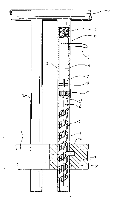
: ~ Figure 1 in side elevation/axial section shows a device
,
!
~, ' ' ~ ' ' ' ~ ,
,' .
~ '
;

13(?S~
2a
for vertical adjustment of arm supports in accordance with the
invention; and
Figure 2 in perspective shows a detail view of the upper
end portion of the motion screw.
.`: ~ :: :
~;:~ : :
,

~ll3~S4Q~;31
In the drawings, reference numeral 1 denotes one of the arm
supports incorporated into a wheel chair frame 1' only shown
partially.
The arm support 1 is carried by a vertical support pipe 2
which is axially displaceably supported in a bore 3l of a
bracket 3 rigidly connected to the chair frame 1' .
Rotationally arranged in the lower portion of the support
pipe 2 is a motion screw 4, the upper portion 4' of which is
formed without screw threads. In between the threads of the
motion screw engages a lug 5 fastened to the bracket 3 and
extending through a longitudinal slot 6 of the support pipe
2. This slot 6 should have a longitudinal extension somewhat
exceeding the desired maximum area of height adjustment for
the arm support 1.
The upper unthreaded portion 4' of the motion screw is
provided with a circumferential groove 4" wherein a lug 7
attached to the support pipe 2 engages. The engagement of
the lug 7 within the circumferential groove 4" of the screw
prevents axial displacement of the screw 4.
A simple handle 8 is rigidly connected to an axially
displaceable locking slide 9 in the support pipe 2, said
locking slide lowermost carrying a locking cotter 10 for
engagement in a preferably cross-shaped groove 11, Figure 2,
formed in the adjacent gable surface of the motion screw.
The locking slide 9 is spring-loaded downwards toward
~locking position, Figure 1, but-the engagement of the
locking cotter 10 within the cross-groove 11 can be released
through moving the handle 8 a short distance upwards in a
slot 13 of the support pipe. Thereby, the locking cotter 10
if lifted clear of the groove 11, whereafter the motion
screw 4 can rotate freely.
,-..

~3(~5~0
Through lifting or lowering the arm support 1 in this
position in order to achieve the desired position of height,
the screw 4 is rotated in the one or other direction, the
stationary lug 5 engaging in between its threads. The
support pipe 2 of the arm support l is thereby displaced
upward or downward until the desired height position of the
arm support 1 is reached. Thereafter, the handle 8 is
released and the spring 12 brings the locking cotter 10 of
the locking slide 9 into engagement within the locking
groove 11 of the screw 4, whereafter the height position of
the arm support is locked.
Through the use of a sufficiently heavy locking slide 9, the
spring may possibly be omitted.
14 denotes a support pipe extending freely through the :l;
bracket 3 and parallel to the support pipe 2.
The arm support height adjusting device according to the
invention is very handy in use. Infinitely variable
adjustment of height is achieved.
Simultaneously, the motion screw offers a small but desired
resistance during the vertical adjustment, which thereby
becomes much more controlled than what previously has been
possible by means of telescopic pipes.
:
:: :
:
, ~
~: ~
.

Dessin représentatif
Une figure unique qui représente un dessin illustrant l'invention.
États administratifs

2024-08-01 : Dans le cadre de la transition vers les Brevets de nouvelle génération (BNG), la base de données sur les brevets canadiens (BDBC) contient désormais un Historique d'événement plus détaillé, qui reproduit le Journal des événements de notre nouvelle solution interne.

Veuillez noter que les événements débutant par « Inactive : » se réfèrent à des événements qui ne sont plus utilisés dans notre nouvelle solution interne.

Pour une meilleure compréhension de l'état de la demande ou brevet qui figure sur cette page, la rubrique Mise en garde , et les descriptions de Brevet , Historique d'événement , Taxes périodiques et Historique des paiements devraient être consultées.

Historique d'événement

Description Date
Inactive : Demande ad hoc documentée 1996-07-21
Le délai pour l'annulation est expiré 1996-01-22
Lettre envoyée 1995-07-21
Accordé par délivrance 1992-07-21

Historique d'abandonnement

Il n'y a pas d'historique d'abandonnement

Titulaires au dossier

Les titulaires actuels et antérieures au dossier sont affichés en ordre alphabétique.

Titulaires actuels au dossier
ARNFINN FROYLAND
THORBJORN LOHRE
Titulaires antérieures au dossier
S.O.
Les propriétaires antérieurs qui ne figurent pas dans la liste des « Propriétaires au dossier » apparaîtront dans d'autres documents au dossier.
Documents

Pour visionner les fichiers sélectionnés, entrer le code reCAPTCHA :


Pour visualiser une image, cliquer sur un lien dans la colonne description du document (Temporairement non-disponible). Pour télécharger l'image (les images), cliquer l'une ou plusieurs cases à cocher dans la première colonne et ensuite cliquer sur le bouton "Télécharger sélection en format PDF (archive Zip)" ou le bouton "Télécharger sélection (en un fichier PDF fusionné)".

Liste des documents de brevet publiés et non publiés sur la BDBC .

Si vous avez des difficultés à accéder au contenu, veuillez communiquer avec le Centre de services à la clientèle au 1-866-997-1936, ou envoyer un courriel au Centre de service à la clientèle de l'OPIC.

({010=Tous les documents, 020=Au moment du dépôt, 030=Au moment de la mise à la disponibilité du public, 040=À la délivrance, 050=Examen, 060=Correspondance reçue, 070=Divers, 080=Correspondance envoyée, 090=Paiement})


Description du
Document 
Date
(aaaa-mm-jj) 
Nombre de pages   Taille de l'image (Ko) 
Abrégé 1993-11-01 1 23
Revendications 1993-11-01 2 58
Dessins 1993-11-01 2 39
Description 1993-11-01 5 161
Dessin représentatif 2000-08-07 1 26
Taxes 1994-06-29 1 53