Note: Descriptions are shown in the official language in which they were submitted.
08/10/~7
~3~33
PSA PROCESS AND APPARATUS
EMPLOYING GASEOUS DIFFUSION BARRIERS
Backqround of the Invention
(1~ Field of the Invention
This invention relates to gas enrichment utilizing
pressure swing adsorption techniques, and more partic-
ularly to an improved pressure swing adsorption process
and apparatus (including gaseous diffusion barriers for
gas enrichment.
(2) Description of the Prior Art
The use of adsorption te~hniques to separate a gaseous
component from a gaseous stream initially was developed
for the removal of carbon dioxide and water from air. The
principles of gas adsorption were further refined to proc-
esses for gas enrichment of hydrogeh, helium, argon, car~
bon monoxide, carbon dioxide, nitrous oxide, oxygen and
nitrogen. Still further refinements using at least two
adsorption vessels in a cycling pressurized relationship
have resulted in an adsorption technique for gas enrich-
ment commonly referred to as pressure swing adsorption
(PSA~.
:: :
~:
~3~ 33
--2--
A conventional PSA process for enriching a gas, ~uch
as nitrogen from air, employs at least two adsorption beds
filled with carbon molecular ~sieve material, each sub-
jected to two or more, generally four distinct processing
steps in each cycle. In a first step of the cycle, one
adsorption bed is pressurized with concomitant nitrogen
production while the other bed is regenerated, such as by
venting. The adsorption bed may also be regenerated with
countercurrent flow of product-quality gas (referred to as
"purge"). In a second step, sometimes referred to as
pressure equalization, the adsorption beds are brought to
an intermediate pressure by interconnection of the adsorp-
tion beds. In a third step of the cycle, the first ad-
sorption bed is regenerated following the procedure used
for the second bed while the second bed is put into pro-
duction. The last step of the cycle is pressure equal-
ization between the beds. During such pressure swings,
pressure conditions in the adsorption beds vary between
about 15 psig to 120 psig in a process employing carbon
molecular sieves for nitrogen production and somewhat
lower pressure ranges in processes employing crystalline
2eolites for producing oxygen.
The use of an oxygen separation membrane in a pressure
swing adsorption process is disclosed in Japanese patent
Application No. Sho 51(1982)-31576, filed February 27,
1982 wherein oxygen is produced by PSA techniques in
adsorption columns filled with zeolites particles and
wherein during the purge cycle of each adsorption column a
oxygen purge gas is passed therethrough. The oxygen purge
gas is obtained as a gaseous permeate stream from a gas
separation membrane into which an enriched oxygen st`ream
is introduced during a production cycle of each of the
adsorption columns.
; .
~S43~
--3--
Obiects of the Invention
An object of the present invention is to pro~ide an
improved PSA process and apparatus of reduced energy
requirements.
Another object of the present invention is to provide
an improved PSA process and apparatus permitting of longer
cycling times.
A further object of the present invention is to pro-
vide an improved PSA process and apparatus capable of
producing high purity product for longer periods of time.
A still further object of the present invention is to
provide an improved PSA process and apparatus advantag-
eously utilizing the pressure levels of vent streams.
Summary of the Invention
These and other objects of the present invention are
achieved in an improved PSA process and apparatus for gas
enrichment wherein the pressure levels of the vent gas
stream and/or product stream are used to drive gaseous
diffusion cells to produce a feed gas stream and/or a
purge gas stream to be used in the pressure swing adsorp-
tion process to increase on-line production time and to
utilize waste pressure energy, thereby decreasing energy
requirements per unit of production.
Brief DescriPtion of the Drawinqs
A better understanding of the present invention as
well as other objects and advantages thereof will become
apparent upon consideration of the detailed description
thereof, especially when taken with the accompanying
d-awings, wherein:
~L3~ 3
--4--
-
FIG. 1 is a schematic flow diagram of a preferred
embodiment of the present invention;
FIG. 2 is a pressure profile of the adsorbent vessels
for a complete cycle of a somewhat standard PSA process;
FIG. 3 is a graph showing a typical vent flow rate as
a function of time for nitrogen PSA according to one em-
bodiment of the present invention;
FIG. 4 is a graph showing a typical vent pressure as
function of time for a nitrogen PSA according to the em-
bodiment of FIG. 3 of the present invention;
FIG. 5 iS a graph showing a typical oxygen concen-
tration as a function of time in a nitrogen PSA according
to the embodiment of FIG. 3 of the present invention; and
FIG. 6 iS a graph showing a typical mole fraction of
nitrogen in the non-permeate stream as a function of time
and stage cut according to the embodiment of FIG. 3 of the
present invention; and
FIG. 7 iS a graph showing power consumption per unit
product as a function of stage cut according to the embod-
iment of FIG. 3 of the present invention.
Detailed Description of the Invention
To facilitate an understanding of the present inven-
tion; certain valving, piping and instrumentation assem-
blies are not illustrated in the drawings, however, it
~will be understood that such additional valving, piping
and instrumentation assemblies are provided consistent
with a~cepted practices in the art. The present invention
will be~described in the context of nitrogen enrichment of
air using an adsorbent bed of carbon molecular sieves,
~although it will be understood by one skilled in the art
.~
,
.
~3~i433
--5--
that the process and apparatus of the present invention
are applicable to gas enrichment, per se, using pressure
swing adsorption techniques.
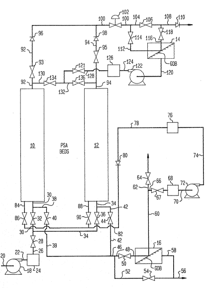
Referring now to FIG. 1, there is illustrated a sche-
matic flow diagram of the process and apparatus of the
present invention including adsorption vessels 10 and 12,
and upper and lower gas diffusion vessels 14 and 16. The
adsorption vessels 10 and 12 are filled with an appropri-
ate adsorption material, such as the aforementioned carbon
molecular sieves. The upper and lower gas diffusion ves-
sels 14 and 16 are provided with suitable gaseous diffus-
ion barriers (GDB), as more fully hereinafter discussed.
The process and apparatus of the present invention is
provided with a feed compressor 18 including an inlet con-
duit 20 on the suction side thereof in fluid communication
with a surge tank 24. The surge tank 24 is provided with
a conduit 26 under the control of valve 28 connected to a
conduit 30 under the control of valve 32 with the lower
portion of the adsorption vessel 10 and to a conduit 34
under the control of valve 36 with the lower portion of
the adsorption vessel 12.
The conduits 30 and 34 connected to the lower portion
of the adsorption vessels 10 and 12 are connected by
conduit 38 under the control of the valve 40 and conduit
42 under the control of valve 44, respectively to a
conduit 46. The conduit 46 is connected by a conduit 48
under the control of valve 50 with a lower gas diffusion
vessel 16 and by a conduit 52 under the control of valve
54 to a vent conduit 56.
The lower gas~diffusion vessel 16 on the permeate side
is provided with a conduit 58 connected to the vent con-
duit 56 and on the non-permeate side is provided with a
conduit 60. The conduit 60 is connected to a conduit 62
under the control of valve 64 and to a conduit 66 under
,
~L36~;433
--6--
. .
the control of valve 67 to a holding tank 68. The holding
tank 68 is provided with a conduit 70 connected to the
suction side of a compressor 72 -with the discharge side
thereof being connected by a conduit 74 to a surge tank
76. The compressor 72 and related surge tank 76 are op-
tionally provided to permit process flexibility. The
holding tank 76 is provided with an outlet conduit 78
including a one-way valve 80 connected to a conduit 82.
The conduit 82 is connected to the lower portion of ad-
sorption vessel 10 by a conduit 84 under the control of
valve 86 and to the lower portion of adsorption vessel 12
by a conduit 88 under the control of valve 90, as more
fully hereinafter described.
The adsorption vessels 10 and 12 are provided with
upper conduits 92 and 94, respectively, under the control
of valves 93 and 95 and including one-way check valves 96
and 98, respectively, connected to a conduit 100. The
conduit 100 under the control of valve 102 is connected to
a conduit 104 under the control of valve 106 with a prod-
uct conduit 108 including one-way valve 110. The conduit
100 is connected by a conduit 112 under the control of
valve 114 to the upper gas diffusion vessel 14. The upper
gas diffusion vessel 14 is provided on the non-permeate
side with a conduit 116 under the control of valve 118
connected to the product conduit 108, and is provided on
the permeate side with a conduit 120 in fluid communi-
cation with the suction side of a compressor 122. The
discharge side of the compressor 122 is connected by a
conduit 124 to a holding tank 126 having a conduit 128
under the control of valve 121 and connected to conduits
130 and 132 under the control of valves 134 and 136 with
upper conduits 92 and 94, respectively, of the adsorption
vessels 10 and 12. Generally, the compressor 122 and
associated holding or surge tank 126 is optionally pro-
vided for process flexibility.
~5~3
-7-
The upper and lower gas diffusion vessels 14 and 16
are commercially available vessels,-such as from UOP Fluid
Systems (A Division of Allied-Signal), and provided with a
suitable gaseous diffusion barrier which uses a silicone-
rubber membrane, or from Monsanto Chemical Company which
uses a polysulfone membrane. The membrane used in the
cells permits gaseous molecular oxygen to pass through the
membranes faster than gaseous molecular nitrogen.
In one aspect of the present invention, the pressur-
ized gas stream withdrawn from an adsorption column during
regeneration following pressure equalization is introduced
into the lower gaseous diffusion vessel 16 wherein there
is formed a non-permeate gas stream relatively depleted in
the adsorbate (ox oxygen) and at an elevated pressure and
a permeate gaseous stream of a higher level of the adsor-
bate which is ~ented. The non-permeate gas stream at an
elevated pressure may be used to directly repressurize an
adsorption bed, to repressurize an adsorption bed after
recompression, to repressurize an adsorption bed following
partial repressurization by equalization, or to be used as
a feed gas stream, as more fully hereinafter discussed.
In another aspect of the present invention. a portion
of the gas enriched product stream, as breakthrough is
approached and product purity level falls off, is intro-
duced into the upper gaseous diffusion vessel to form a
non-permeate stream, i.e. a gaseous stream of a purity
consistent with product design criteria, and a permeate
stream to be used for purge and/or backfill, as more fully
hereinafter discussed. The use of both the upper and
lower gaseous diffusion assemblies may be efficaciously
integrated into existing PSA plants.
In operation, let it be assumed that the apparatus is
in operation in a PSA process for producing high purity
nitrogen, e.g. 99.9% nitrogen at a pressure of from 60 10
~3~ 33
--8--
150 psig, wherein the adsorption vessel 10 has been
desorbed and is ready for production following pressur-
ization, whereas the adsorption vessel 12 requires
regeneration, and prior to that pressure equalization or
balancing has been effected between the adsorption vessels
10 and 12. In describing the operation of the following
steps, only the valves opened during each step are men-
tioned, it being understood that the remaining valves are
closed. In this condition, valves 28, 32, 44, 50, 67, 93,
102 and 106 are opened.
For pressurization of adsorption vessel 10 and for
production, air at ambient temperature in inlet conduit 20
is compressed in compressor 18 to a pressure of from 65 to
155 psig and passed by conduit 22 to the surge tank 24 and
thence by conduits 26 and 30 to the lower portion of the
adsorption vessel 10. The compressed air is introduced at
a pressure of about 55 to 155 psig into adsorption vessel
10 wherein oxygen is selectively adsorbed therein to form
a nitrogen-enriched gaseous stream withdrawn from adsorp-
tion vessel 10 by upper conduit 92 and passed at a pres-
sure of from 60 to 150 psig by conduits 100, 104 and 108
to product storage or user eguipment (not shown).
The flow of compressed air to adsorption vessel 10 is
continued until a point i5 reached where the level of oxy-
gen in the nitrogen product gaseous stream reaches a pre-
determined threshold value unacceptable for product
usage. For example, the average oxygen content of the
nitrogen-enriched product stream may be 1000 ppmv 2
whereupon a predetermined threshold value may be 1200 ppmv
2
At the point of reaching such a predetermined thresh-
old value, the nitrogen-enriched gaseous stream ~or
"tail-end" product~ in conduit 100 is purified in the
upper gaseous diffusion vessel 14 by closing valve 106 to
~IL3~5~3~
_9_
provide a non-permeate gas stream of acceptable purity
withdrawn by conduit 116 and passed to product conduit
108. The permeate stream (the steam permeating the
diffusion cell), slightly enriched in oxygen and at a
lower pressure level, is passed by conduit 120 under the
con-trol of valves 121 and 136 at a pressure level of from
15 to 50 psig to the adsorption vessel 12 as a purge gas
or as backfill for the adsorption bed undergoing regener-
ation. In this condition, valves 28, 32, 44, 54, 93, 102,
114, 118, 121 and 136 are open. The compressor 122 and
associated holding tank 126 are optionally provided as
hereinabove discussed. The flow of gaseous product in
conduit 100, having a level of impurity higher than
threshold value, is continued to the upper gas diffusion
vessel 14 for a period of time where further ~ncrease in
the concentration of oxygen warrants shutdown of adsorp-
tion vessel 10 and the regeneration thereof.
At the initiation of pressurization of the adsorption
vessel 10 prior to production of an enriched gaseous
stream the adsorption vessel 12 has undergone pressure
equalization or pressure balancing and is concomitantly
readied for the blowdown cycle. During this condition,
valves, 28, 32, 44, 50 and 67 are opened to allow pres
suri2ation of adsorp-tion vessel 10 and to permit a flow of
gas from the adsorption vessel 12 through the conduits 34,
42, ~6 and 48 into the gaseous diffusion vessel 16 includ-
ing a suitable gaseous diffusion barrier (GDB). In the
gaseous diffusion vessel 16, oxygen readily passes through
the gas-permeable membrane (GM). An oxygen-enriched gas-
eous stream ~permeate) is withdrawn from the gas diffusion
cell 16 by conduit 58 and passed via conduit 56 to vent.
The non-permeate gaseous stream formed in the gaseous
diffusion vessel 16 is available at a pressure of from at
least about 15 to a pressure range of from 15 to 75 psig,
as more fully hereinafter discussed. Upon reaching a
predetermined concentration le~el of N2, e.g. 79% or
;33
--10--
alternately determined by a pressure level of from 15 to
- 30 psig in the non-permeate stream, generally as deter-
mined by cycle time versus gas analysis, the valve 50 in
conduit ~8 is closed and valve 54 in conduit 52 is opened
to permit the gas stream in conduit 46 to be passed to
vent via conduit 56.
As hereinabove discussed, the permeate stream and
non-permeate gaseous stream formed in the upper and lower
gas diffusion cells 14 and 16 may be used in diverse ways
to improve the process of gas enrichment utilizing pres-
sure swing adsorption techniques. With regard to the use
of the lower gaseous diffusion cell 16, the non-permeate
stream in conduit 60 may be used to repressurize via con-
duit 62 one or more regenerated beds (not shown) in a
multi-bed PSA system which is generally effected concur-
rently with venting but before pressure equalization.
Depending on the cycling times of such regenerated beds,
the non-permeate stream may be passed to a holding tank 68
prior to introduction into such regenerated beds during
repressurization. Still further, in a multi-bed PSA
system, i.e. two or more adsorption vessels, each non-
permeate stream in conduit 66 may be compressed in
compressor 72 and may be passed by conduit 82, in lieu of
compressed air from holding tank 24 for the initial stage
of product delivery. In a multi-bed PSA system, i.e. two
or more adsorption vessels, such non-permeate stream may
be passed in lieu of compressed air for the initial stage
of product delivery prior to admission of compressed air
for the repressurization step.
As illustrated in FIG. 2 in a normal PSA operation, at
the end of product delivery from adsorption vessel 10, the
adsorption vessel 12 will have undergone regeneration in-
cluding blowdown and venting at which time the adsorption
vessel lZ is readied for production and the adsorption
vessel 10 is readied for regeneration. At such time,
:
33
--11~
valves 32, 36, 134 and 136 are opened to effect pressure
equalization be~ween the adsorption vessels 10 and 12.
The step of pressure equalization is effected for a
time sufficient for such purpose, generally of from 2 to
20 seconds depending on the volume and type of the bed of
adsorption material in the adsorption vessels 10 and 12.
The step of pressure e~ualization for the PSA process of
this invention is the same as in a normal PSA process;
however, it is effected after processing the vent from the
adsorption vessel undergoing regeneration with the lower
gaseous diffusion cell and after processing tail-end
product from the in production adsorption vessel with the
upper gaseous diffusion cell.
At a preselect time in the operational cycle, adsorp-
tion vessel 12 is placed in a nitrogen production mode and
the adsorption vessel 10 into a regeneration mode. In
this condition, valves 28, 36, 40, 50, 67, 95, 102 and 106
are opened. Accordingly, compressed air in conduit 22 is
now passed through conduits 26 and 34 to the adsorption
vessel 12 to form a nitrogen-enriched product gaseous
stream which is withdrawn from the adsorption vessel 12
through conduit 94 and passed by conduits 100, 104 and 108
to product storage. Regeneration of the bed of adsorbent
material in adsorption vessel 10, i.e. blowdown and vent-
ing are effected in like manner to that of the bed of
adsorption material in adsorption vessel 12. During re-
generation, a gaseous stream is withdrawn from adsorption
vessel 10 by conduit 38 and is passed through conduits 46
and 48 under the control o valve 50 to lower diffusion
cell 16 as her inabove described.
At the completion of regeneration of the bed of
adsorption material in the adsorption vessel 10 and the
completion of product delivery from the adsorption vessel
12 including the purification of the tail-end product in
13~ 33
-12-
the upper gaseous diffusion cell 14, the valves 32, 36,
13~ and 136 are opened to initiat and permit the step of
pressure equalization.
In accordance with one aspect of the present invention
as hereinabove discussed, the gaseous stream withdrawn
from an adsorption vessel in the conduit 46 at the incep-
tion of blowdown is at an elevated pressure of from 40 to
75 psig and is passed by conduit 48 under the control of
valve 50 to the gaseous diffusion vessel 16, generally to
a point where the pressure in the conduit 46 reaches about
15 psig. Upon reaching such pressure, the gaseous stream
is vented to atmosphere by closing ~alve 50 and opening
valve 54 to permit gaseous flow through conduit 52.
EXAMPLES
The following examples are illustrative of the process
of the present invention, and it is to be understood that
the scope of the invention is not to be limited thereby.
Example I
The PS~ vent, after pressure equalization between
beds, is passed through the lower dif~usion cell (poly-
sulfone membrane). Referring to FIG. 1, the nitrogen-
enriched non-permeate stream from the lower diffusion cell
is sent to the holding tank 68 and is then compressed to
the feed pressure in compressor 72. The compressed gas in
the holding tank 76 is introduced as feed to the adsorp-
tion vessels 10 or 12 during part of the production cycle.
FIGS. 3 to 5 illustrate vent flowrate, vent pressure,
and vent oxygen concentration as a function of time for a
nitrogen PSA employing BF (Bergbau-Forschung, West Germ-
any) carbon molecular sieve and operating on a 2 min. ~ull
cycle. The operating pressure is 120 psig and the pro-
.
:
. ' ~ .
~3q:1~43~
-13-
files shown in FIG.S 3 to 5 are for the bed undergoing
regeneration by venting. The nitrogen concentration pro-
files for polysulfone membrane, as a function of stage-cut
(fraction of feed permeating the membrane), are shown in
FIG. 6. The energy required to compress the fraction of
non-permeate stream with a nitrogen concentration above
7g~O to feed pressure (120 psig) was calculated as a
function of staqe cut.
Significant energy savings are realized since the
non-permeate stream requires relatively smaller compres-
sion to be raised to feed pressure because of it being at
a pressure higher than atmospheric, while fresh feed has
to be compressed to operating pressure starting at atmos-
pheric pressure. FIG. 7 shows relative power requirements
to produce a unit amount of product in the absence a dif-
fusion cell, versus a diffusion cell containing polysul-
fone membrane. The optimum performance is obtained for a
stage cut of about 50% and for this case about 8.5% energy
savings are possible for polysulfone membranes and real-
ized by use of a lower gaseous diffusion cell to provide a
portion of the gaseous feed.
. ' '
.
~3~S~33
-14-
~xAMæL~ II
The following e~ample illustrates the cycling time
for a PSA process using a non-permeate gas stream formed in the
gaseous diffusion vessel 16 to pressurize an adsorption bed
prior to pressure equalization (Valves - FIG. 1): :
Typical
Times
Step Vessel lQ Vessel 12 Valves Open 1 ec.)
1 Pressurize with Vent through lower28, 32, 44, 10
fresh feed diffusion cell 50, 67
2 Produce N2 product Vent through lower 28, 32, 44, 30
diffusion cell 50, 67, 93,
102, 106
3 Produce N2 product Vent directly to 28, 32, 44, 70
atmosphere 54, 93, 102,
106
4 Produce N2 product Pressurize with 28, 32, 90, 5
gas from lower 93, 102, 106
diffusion cell
Pressure equalization Pressure equalization 32, 36, 134, 5
with Vessel 12 with Vessel 10 136
6 Vent through lower Pressurize with 28, 36, 40, 10
diffusion cell fresh feed 50, 67
7 Vent through lower Produce N2 product 28, 36, 40, 30
diffusion cell 50, 67, 95,
102, 106
8 Vent directly to Produce N2 product 28, 36, 40, 70
atmosphere 50, 95, 102
106
9 Pressurize with gas Produce N2 product 28, 36, 86, 5
from lower diffusion 95, 102, 106
cell
10 Pressure equalization Pressure equalization 32, 36, 134, 5
with Vessel 12 with Vessel 10 136
4 min./cycle
': ,
. ': ',, .' . ,'' ' ',. : ' , ' '
-
.
. . . .
~L3~43:3
-15-
EXAMPL~ III
The following example illustrates the cycling time for
a nitrogen process in which a permeate stream from the gaseous
diffusion vessel 14 is used to purge one of the adsorption beds
(Valves - FIG. 1):
Typical
Times
Vessel 10 Vessel 12 Valves Open (sec.)
1 Pressurize with Vent directly to 28, 32, 44, 10
fr~sh feed atmosphere 54
2 Produce ~2 product Vent directly to 28, 32, 44, 100
atmosphere 54, 93, 102,
106
3 Purify product with Purge Vessel 12 28, 32, 44, 35
upper diffusion cell, with permeate from 54, 93, 102,
provide purge for upper diffusion cell 114, 116, 121,
Vessel 12 136
4 Pressure equalization Pressure equalization 32, 36, 134, 5
with Vessel 12 with Vessel 10 136
Vent directly to Pressuriæe with 28, 36, 40, 10
atmosphere fresh feed 54
6 Vent directly to Produce N2 product 28, 36, 40, 100
atmosphere 54, 95, 102,
106
7 Purge with permeate Purify product with 28, 36, 40, 35
from upper diffusion upper diffusion cell, 54, 95, 102,
cell provide purge for114, 116, 121,
Vessel 10 134
8 Pressure equalization Pressure equalization 32, 36, 134, 5
with Vessel 12 with Vessel 10 136
5 min./cycle
-16- ~3~ 3
~XAMPL~ IV
The following example illustrates the cycling time for
a PSA process using the combined processing steps as disclosed
in Examples II and III (Valves - FIG. 1):
Typical
Times
Vessel 10 Vessel 12 Valves Open (sec.
1 Pressurize with Vent through lower 28, 32, 44, 10
fresh feed diffusion cell 50, 67
2 Produce N2 product Vent throu~h lower 28, 32, 44, 30
diffusion cell 50, 67, 93,
102, 106
3 Produce N2 product Vent directly to 28, 32, 44, 70
atmosphere 54, 93, 102,
106
4 Purify product with Purge Vessel 12 28, 32, 44, 30
upper diffusion cell, with permeate from 54, 93, 102,
provide purge for upper diffusion cell 114, 116, 121,
Vessel 12 136
Pressurize with 90 5
gas from lower
diffusion cell
6 Pressure equalization Pressure equalization 32, 36, 134, 5
with Vessel 12 with VesseI 10 136
7 Vent through lower Pressurize with 28, 36, 40, 10
diffusion cell fresh feed 50, 67
8 Vent through lower Produce N2 product 28, 36, 40, 30
diffusion cell 50, 67, 95,
102, 106
9 Vent directly to Produce N2 product 28, 36, 40, 70
atmosphere 54, 95, 102
106
10 Purge with permeate Purify product with 28, 36, 40, 30
from upper diffusion upper diffusion cell, 54, 95, 102,
cell provide purge for 114, 116, 121,
Vessel 10 134
11 Pressurize with gas 86 5
from lower diffusion
cell
12 Pressure equalization Pressure equalization 32, 36, 134, 5
with Vessel 12 with Vessel 10 136
:
.
.
.
~36~ 33
-17-
-
By using the process of the present invention as
directed- to the use of gaseous diffusion vessels the
result is a reduction in energy requirements of from 5 to
15% per unit of product depending on the type of membrane
material used in the di~fusion cells.
The present invention has been described in the con-
text of PSA processing technology in the production of a
nitrogen-enriched product stream; however, it will be
understood by one of ordinary skill in that art that the
present invention is applicable to gas enrichment tech-
nology, per se, using pressure swing adsorption techniques.
While the present invention has been described in con-
nection with an exemplary embodiment thereof, it will be
understood that many modifications will be apparent to
those of ordinary skill in the art, and that this applica-
tion is intended to cover any adaptations or variations
thereof. Therefore, it is manifestly intended that this
invention be only limited by the claims and the equival-
ents thereof.