Note: Descriptions are shown in the official language in which they were submitted.
~3~
Composting E~uipment
Technical Field
The invention refers to composting equipment for
crushing organic waste, particularly wood, comprising
(a) an elongated trough-shaped container having a
bottom, opposite side walls a first end and a
second end,
(b~ a conveyor device which extends along said
conveyor, said conveyor device ~eing arranged to
convey material placed thereon in a conveying
direction longitudinally of said elongated trough
towards said one or first end
(c~ an impact mechanism arranged at said one or
; first end of the container to receive material from
said conveyor device on an inlet side, to crush
such material and, on an outlet side, to expel such
crushed material from said container at said one or
first end.
Background Art
Large quantities of organic waste develops in
forestry, at municipal corporations or road building and
maintenance authorities, for example waste wood when road
~:'
~3~
trees are trimmed, wastes from cemeteries or also waste
woods from the disposal of bulky goods or the household
rubbish. ~t is desirable not to burn such waste wood or to
feed it to a garbage incineration facility but to compost it
for generating natural humus. The environment is heavily
burdened by burning or by a garbage incineration facility.
Besides burning in a garbage incineration facility involves
considerable costs. Therefore it is known to comminute
waste wood and to pit it such that it changes into humus by
natural decomposition. To accelerate the rotting, rotting-
stimulating agents, for example lime nitrogen are added tothe comminuted organic wastes.
A composting equipment for crushing wood and other
organic waste is illustrated and described in German patent
document 3,517,684. In the embodiment illustrated and
described there, the composting equipment is arranged on the
loading area of a motor truck and is driven by the internal
combustion engine of the truck through a mechanical or
hydraulic power connection which is normally present in a
motor truck. From German patent document 3,517,684 it is
also known to remove the composting equipment from the motor
truck by means of a conventional quick change attachment.
Then the motor truck is also available for other purposes.
In this case however the composting equipment cannot be
used, because the drive by the motor truck is disconnected.
.!
. . . .
```` ~3~
The known arrangement is non-uniformly loaded
because of a heavy load, namely the heavy impact mechanism,
at the rear end.
Disclosure of Invention
.
S It is the object of the invention to provide
composting equipment of the type mentioned above which can
be handled easier, because the non-uniformly loading is
eliminated and which enables operation independent of the
internal combustion engine of a motor truck.
According to the invention this object is achieved
in that
(d) a driving engine is attached to the container
at its other or second end, remote from the impact
mechanism, and
(e) the driving engine is coupled to the impact
mechanism by power transmission means which extend
along the trough-shaped container.
The driving engine makes the composting equipment
independent of an external drive. Therefore the compcsting
equipment can also ~e used as a quasi stationary machine
after being removed from the motor truck. In addition the
heavy driving engine constitutes a counter-weight arranged
at the end remote from the impact mechanism. Therefore the
composting equipment can be handled easier than the prior
art composting equipment in spite of its higher weight.
,.,
. .
A~,
., . _ _ .. _ . . . . , , _ . ~.. _
4 A ~3~
Modifications of the invention are subject matter
of the dependent claims.
In a further aspect, the invention provides
composting equipment for crushing organic waste, comprising:
an elongated trough-shaped container having a
bottom, opposite side walls and a first and a second end, a
conveyor device which ex~ends along said elongated trough-
shaped container between said first and second ends of said
elongated trough-shaped container,
said conveyer device serving for conveying material
placed thereupon in a conveying direction longitudinally of
said elongated trough-shaped container ~oward said first end
of said elongated trough-shaped con~ainer,
an impact mechanism arranged at said first end of
the elonga~ed trough-shaped container and having an inlet
side and an outlet side,
said impact mechanism receiving, on its inlet side,
: said material conveyed by said conveyer device towards said
firs~ end of said elongated trough-shaped container for
crushing said material,
said impact mechanism expelling, on it output side,
the received material in a crushed condition,
: said impact mechanism comprising a horizontal shaft
driven to rotate about an axis of rotation and carrying
flails arranged to hit the material to be crushed during
:~:
,
: ,1,';
, ~ -'
``` 4B ~3~ , f~
such a rotation, the direction of rotation of the impact
mechanism being such that the flails, on the side of the
conveyer device, are moved upwards,
said conveyer device being arranged in or above a
horizontal plane extending through said axis of rotation of
said horizontal shaft,
a driving engine attached to said elongated trough-
shaped container at said second end of said elongated
trough-shaped container and opposite to said impact
mechanism as viewed in said conveying direction of said
conveyer device,
power transmission means for coupling said driving
engine with said impact mechanism and driving said
horizontal shaft to rotate about said axis of rotation, and
said power transmission means extending along said
elongated trough-shaped container.
:::
- - - ~ .- ... . ..
Brief Description of the Drawings
An embodiment of the invention will now be
described in further detail with reference to the
accompanying drawings.
Fig. 1 shows a side elevation of the composting
equipment.
Fig. 2 shows details of the conveyor device and of
the impact mechanism.
Fig. 3 is an end view of the impact mechanism~
Best Mode of Carr in Out the Invention
Y g
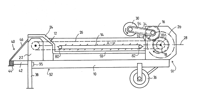
, A trough-shaped container 12 having opposing
sidewalls 12A is located on a chassis 10. A conveying
device 14 extends along a bottom 93 of this container 12
between side walls 12A. The conveying device 14 is arranged
lS to convey material to the right or first end 91 of the
container 12 in direction A shown by the arrow, as viewed in
~ the figure. An impact mechanism 16 is arranged at this end
;; ~ 91. The impact mechanism 16 closes the container 12. The
impact mechanism 16 is of similar construction as that
; 20 disclosed in German patent document 3,517,684 and therefore
; ~ is not illustrated and described in further detail here.
-~ ~ The impact mechanism 16 comprises flails which rotate about
-~ axis of rotation 18A of a shaft 18 within the cylindric area
' ~ :
:
4t~i~
20 indicated by the dashed-and-dotted line. Material, for
example branches, boards, stems etc., which is thrown into
the container 12, is transported to the impact mechanism 16
by the conveying device 14 and is treated there by the
flails until the pieces of wood or elements of wood are
- crushed to small pieces. This is described in detail in
German patent document 3,517,684.
A driving engine 22 is attached to the container
12 at its second end 92 remote from the impact mechanism
16. The driving engine 22 is located on the chassis 10 and
is covered by a shield 24 which is integral with the second
; end 92 of the container 12. The driving engine 22 is
coupled to the impact mechanism 16 by a power transmission
26 which extends along the trough-shaped container 12.
In German patent document 3,517,684 a heavy chain
curtain is arranged in front of the impact mechanism 16.
This chain curtain is intended to prevent material from
being catapulted back to the rear by the impact mechanism.
In the prior art composting equipment a conveying device is
arranged below the shaft of the impact mechanism. Thereby
the flails hit the material in the direction ~rom "right
below" in fig. 2 of German patent document 3,517,684 and
catapult the material to the direction "right top", that
means opposite to the conveying direction of the conveying
device back into the container.
';
: ' .
, , , . . , , . ~ -
L33~
~ 7
In the present embodiment, however, the conveying
device 14 is arranged in or above a plane 2a extending
through the shaft 18. Thereby the material is at the most
hit vertically from below such that it is catapulted
vertically to the top against a rebounding wall arranged
there.
Instead of the chain curtain a heavy barrel 30
extending transversely above the conveying device 14 is
arranged at the inlet side of the impact mechanism. This
barrel 30 is supported by a stop 32 and is movably guided by
an arm 34 for upward movement. The barrel 30 is driven by a
driving means 94 in the sense of pulling the material which
is to be crushed into the impact mechanism 16. In the
figure barrel 30 is driven counterclockwise around axis of
rotation 18A of the shaft 18 as illustrated. By this barrel
~ 30 the material is compressed for processing by impact
; mechanism 16~
The trough shaped container 12 is supported by a
pair of wheels 36 at Eirst end 91 adjacent the impact
mechanism. A pair of supports 38 can be releasably attached
of releasable attachment at means 95 to the trough-shaped
contalner 12 at the second end 92 adjacent the driving
engine 22. Furthermore the trough-shaped container 12 is
designed such that coupling means 40 for a tractor can be
attached at the second end 92 adjacent the driving engine
':
t~
~3~
22. These coupling means 40 comprise a drawbar 42 attached
to the chassis 10 in the middle of the left end face
thereof. This drawbar has a coupler socket 44 at its end.
The coupler socket is connected to two struts 46 which are
arranged to form a "vn. The struts 46 are connected with
their free ends to shield 24 provided for the driving engine
22. Thus the coupler socket 44 is connected to three points
of the structure by the drawbar 42 and the strut 46.
When the composting e~uipment is slightly
displaced at its site of operation, this can be done by the
shovel do~er r which is normally present for charging the
container 12 by, engaging the coupler socket 44. After
removing the supports 38 at the releasable attachment means
95, if necessary, the whole composting equipment can be
lifted and can be pulled forwards on the wheels 36. The
coupler socket 44 can also be used for coupling the
composting equipment to a tractor It is, however, also
possible to pull the composting equipment onto the loading
area of a suitable motor truck.
As can be seen from ~igs. 2 and 3, the impact
mechanism 16 comprises a shaft 50 having an axis of rotation
52. A plurality of spaced discs 54 are attached to shaft
50. Off-axis axles 56 extend between these discs 54.
Flails 58 are rotatably mounted on the axles 56. These
~lails 58 are pulled outwards by centri~ugal force, when the
:
~7
~3~i4~
shaft 50 rotates. The range of action of the flails 58 is
limited by the notional cylinder surface 20. The direction
of rotation of the impact mechanism 16 as illustrated by
arrow 60 is such, that the flails, on the side of the
conveyor 14, i.eO on the left in Fig. 2, are moved
upwards. An impact surface 62 is provided above the said
notional cylinder surface 20. The impact surface 62 and the
notional cylinder surface 20 define a narrow exit slit 64.
The waste to be crushed is conveyed in direction A
by the conveyor device 14 into the range of action of the
impact mechanism 16. There the material is chopped and
crushed by the flails 58 and thrown against the impact
surface 62. Then it falls down again from the impact
surface 62. The conveyor device 14 takes care of always
returning the rebounding material to the range of action of
the flails 58. In this range the materlal is exposed to the
action of the flails 58, until it has been reduced to a size
permitting passage through the exit slit 64.
Nevertheless material pieces may get into the
space behind the exit slit 64 during the rotation of the
impact mechanism 16, without having been crushed
sufficiently. In order to ensure the chopping and crushing
;~9 also of those parts, a row of retainer claws 66 is provided
; ~ on the outlet slde of the outlet slit 64. These retainer
~ ~5 claws 66 extend into the interstices between the rotating
,
:. ,~ .
~ I ' . .
.. ... , . , . . . . . . . . .. . ~
3~3~
flails 58, as can be seen from Fig. 3. The material pieces
which have bypassed the exit slit 64, will retained by the
retainer claws 66 and will be further chopped and crushed by
the flails 58 passing between the retainer claws 66. A
further impact surface 68 is provided on the exit side of
the retainer claws 66. This impact surface 68 extends at an
angle to the bottom towards the outlet side. This further
impact surface 68 has transverse projections 70, which re-
direct the material thrown against the impact surface 68
back into the range of action of the impact mechanism 16.
Thus also the material~ which has got in front of the
retainer claws 66 and is cut there, will be returned once or
twice into the range of action of the impact mechanism 16,
whereby complete comminution is achieved.
lS If parts such as pieces of iron o~ concrete are
fed to the impact mechanism 16 and cannot be chopped and
crushed by the impact mechanism, provisions have to be made
to avoid damage o the impact mechanism.
For this reason, the flails 58 are pivotable to an
extent that they can be pivoted into the area within the
circumference of the discs 54. Thus if the flails 58 are
unable to chop a material part, the flails 58 can yield and
pass this part within the discs 54. If such part then gets
in front of the retainer claws 66, damage of the retainer
claws 66 is prevented by a structure 70 which permits also
1 . .
the retainer claws 66 to yield, if they are subjected to
excessive Eorce. ThiS structure comprises a biased spring
72, which urges the retainer claws 66 against a stop 74.
As can be seen from Figs. 1 and 2, the conveyor
device 14 comprises a plate 76 extending along the sidewalls
12A the container 12, and a pair of endless conveyor chains
78 passed over two sprocket wheels 80 and 82. The conveyor
chains 78 extend along the two longitudinal edges of the
plate 76. The forward paths of the conveyor chains 78
extend above the plate 76. The conveyor 14 comprises also
transverse ledges 84 the ends of which are connected with
the conveyor chains 78. When the conveyor chains 78 are
driven, the ledges 84 move over the plate 76 and thereby
take along all material placed on the plate 76 and feed it
to the impact mechanism 16.
As can be seen also from Fig. 2, the plate 76 of
the conveyor device 14 is arranged in, but may also be
arranged above the horizontal plane 28 through the axis of
rotation 18A.
,~