Language selection

Search

Patent 1305568 Summary

Third-party information liability

Some of the information on this Web page has been provided by external sources. The Government of Canada is not responsible for the accuracy, reliability or currency of the information supplied by external sources. Users wishing to rely upon this information should consult directly with the source of the information. Content provided by external sources is not subject to official languages, privacy and accessibility requirements.

Claims and Abstract availability

Any discrepancies in the text and image of the Claims and Abstract are due to differing posting times. Text of the Claims and Abstract are posted:

  • At the time the application is open to public inspection;
  • At the time of issue of the patent (grant).
(12) Patent: (11) CA 1305568
(21) Application Number: 1305568
(54) English Title: EQUIPMENT FOR THE ANAEROBIC PURIFICATION OF WASTE WATER
(54) French Title: MATERIEL DE PURIFICATION ANAEROBIQUE DES EAUX USEES
Status: Term Expired - Post Grant
Bibliographic Data
(51) International Patent Classification (IPC):
  • C2F 3/28 (2006.01)
  • C2F 1/00 (2006.01)
(72) Inventors :
  • VELLINGA, SJOERD HUBERTUS JOZEF
(73) Owners :
  • PAQUES B.V.
(71) Applicants :
  • PAQUES B.V.
(74) Agent: MCCARTHY TETRAULT LLP
(74) Associate agent:
(45) Issued: 1992-07-21
(22) Filed Date: 1987-05-01
Availability of licence: N/A
Dedicated to the Public: N/A
(25) Language of filing: English

Patent Cooperation Treaty (PCT): No

(30) Application Priority Data:
Application No. Country/Territory Date
8601120 (Netherlands (Kingdom of the)) 1986-05-01

Abstracts

English Abstract


ABSTRACT
To avoid considerable vertical and horizontal flows in
the settler formed by gas collection hoods, of the upflow
anaerobic sludge blanket (U.A.S.B.) reactor, each gas collection
hood debouches at one or two ends into a gas collection chamber
via one or more openings, the upper boundary of said openings
being situated below the inside surface of the projection or the
top of the hood concerned. The gas collection hoods are
situated immediately below the level of the effluent discharge
and the depth of the settler is shallow. As a result of the
decrease in pressure only a few gas bubbles are consequently
liberated and the settling of the sludge is not appreciably
disturbed.


Claims

Note: Claims are shown in the official language in which they were submitted.

WE CLAIM:
1. Equipment for the anaerobic purification of waste water comprising a reactor with
fermentation section, a settler provided above said fermentation section, means for feeding
waste water to the fermentation section, and means provided at the top of or above the settler
for the discharge of purified water, which settler comprises at least one tier of gas collection
hoods, characterized in that each gas collection hood includes a gas discharge means located
at at least one end thereof, each gas discharge means including, in communication, an inlet
means for gas to be discharge open to said hood and located below the top of said hood,
and an outlet means for gas to be discharged having an upper boundary located below said
inlet means, so as to prevent liquid from flowing into said gas discharge means.
2. Equipment according to claim 1, additionally comprising a gas collection chamber in
communication with said outlet for gas to be discharged.
3. Equipment according to claim 2, wherein said discharge means comprises a receptacle
including a plurality of walls, one said wall including said inlet means for gas to be
discharged, and an other said wall including said outlet means for gas to be discharged.
4. Equipment according to claim 3, wherein said inlet means is located in a wall facing
the top of the hood or in a wall facing the length of the hood, and said outlet means is
located in a wall facing the gas collection chamber.
-5-

Description

Note: Descriptions are shown in the official language in which they were submitted.


~3~.15~
The invention relates to equipment for the anaerobic
pur;fication of waste water, comprising a reactor with a
fermentation section, a settler provided above sa;d fermen-
tation section, means for feeding waste ~ater to the fermen-
tation section, and means provided at the top of or abovethe settler for the discharge of pUf ified ~ater, which
settler comprises at least one tier of gas collection hoods.
Such equipment is in practice often described by the
term U.A.S.~. reactor, U.A.S.B. standing for "up~low anaero-
bic sludge blanket". Known equipment of this type oftenhas two tiers of gas collection hoods, each hood of the
lowermost tier being connected, for example, by an inclined
p;pe to a hood of the uppermost t;er. Ho~ever, a settler
with a single tier of gas collection hoods is also possible.
All the gas collected flows from the gas collection hoods of
the lowermost tier or the single tier directly to a gas
discharge pipe ~hich is connected~ for example, to a gaso-
meter. This known type of anaerobic purification system
may exhibit ~he disadvantage that as a result of turbulænce,
sludge and water are incompletely separated from each other
in the settler, ~h;ch has a detrimental effect on the
efficiency of the systemD Said turbulence is due, ;nter
alia, to upward fLows be;ng produced in the settler due to
miniscule small gas bubbles. These gas bubbles are produced
as a result of it being possible for the ~ater at greater
depth to have more gas in solu~ion than water at the surface.
During up~ard flo~ this supersaturation of gas ~ill emerge
from the uater in the form of small bubbles. Once such a
flow has been produced, it maintains itself as a result of
the gas lift starting to operate and transporting water from
greater depths. This has the result that large ver~ical and
horizon~al flo~s are produced in the settler.
The object of the invention is to avoid this dis-
advantage to a substantial e~tent and provide an anaerobic
~' ~
.
,

~3~
pur;f;cation system of the type mentioned in the introduction
in ~hich at least the ~one near the means for dischar~ing
purified water, usually constructed as overflou troughs, is
largely free of turbulence and the separation between sludge
and water is therefore improved.
According to the invention, the equipment for this
purpose is characterized ;n that each gas collection hood
debouches at at least one end into a gas collection chamber
via one or more openings, the upper boundary of said openings
being situated below the inside surface of the projection
or the top of the hood concerned.
As a result of using the invention, thP only per~itted
flow is the flow of effluent~ aecause the gas coLlection
hoods are placed i~mediately below the level of the effluent
discharge and the depth of the total settler is low, at most
only a fe~ gas bubbles are liberated as a result of the
decrease in pressure and the settling of the sludge cannot
be appreciably disturbed.
Preferably, liquid-retaining ~eans which prevent
~iquid flowing into the gas collection chamber during oPera-
tion are provided near said openings.
There are variows possibilities for constructing the
liquid-retaining ~eans, for exanple, valves ~hich respond
to gas pressure or liquid level. With a view to simplicity
and operational reliability it is, however, preferable that
said means consist of a receptacle with one or more openings
in the rear wall facing the gas collection cha~ber and one
or more openings in the upper or front wall~ the liquid
overflo~ level of said upper or front ~all being situated
above the ~op edge of the opening(s) in the rear wall.
The invention will no~ be exPla;ned in more detail
on the basis of the figures which show an exemp(ary embodi-
ment.
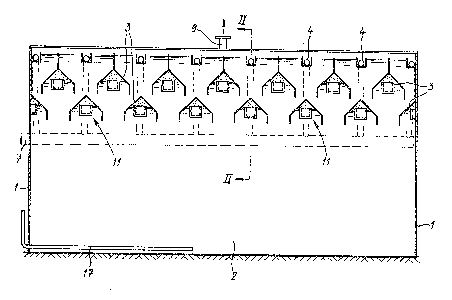
Figure 1 shows a cross section through the reactor
along the line I-I in Figure 2.
figure 2 shows a section along the line II-II ;n
Figure 1.
Figure 3 shows a perspective view of a gas collection

~3~
~ .
- 3 -
hood at the place where the latter debouches into the gas
collection chamber, a part being imagined as broken away.
The equipment shown comprises a reactor 1, the lower-
most part of ~hich forms the fermentation section 2, while
above said section 2 there is provided a settler in the form
of t~o tiers of gas collection hoods 3. Above the upper-
most tier of hoods 3 there is situated a number of overflow
troughs 4 with V-shaped cutouts 5 in the side walls. These
effluent troughs are intended to collect purified water.
from each overflow trough 4 there runs a discharge pipe 6
to a discharge collection point 7.
Each gas collection hood 3 debouches at one end into
a gas collection chamber 8 which is connected to a gas
discharge 9. At the position of this debouchment a small
receptacle 11 is provided consisting of a continuous front
wall 12, continuous side wall 13 and a continuous base 14.
The rear surface and the top surface of the small receptacles
are open or provided with openings, the upper edge of the
opening or openings in the rear surface being indicated by
20 15 and the upper edge of the front wall 1Z by 16. It will
be explained later why it is of importance that 16 is higher
than 15.
A feed pipe 17 for waste water debouches into the
fermentation section 2.
The operation of the equipment is as follows:
A layer of anaerobic sludge is provided on the bottom
of the fermentation section 2. Waste water is fed v;a the
pipe 17 and distributed over the bottom of the container 1
by means known per se which are not drawn. As a result of
anaerobic fermentation, organic material is converted, inter
alia, into fermentation gas (methane) which partly dissolves
in the water and partly rises in the form of gas bubbles.
The liquid level rises as a result of the influent fed in
until said level reaches the top edge of the effluent
troughs 4 and said troughs are f;lled with a current of
purified water. Said purified water is discharged via the
pipes 6 and 7~
The rising gas is collected in the gas collection

~q`
-- 4
hoods 3 and flows out of said hoods via the open top surface
and open rear surface of the small receptacles 11 into the
gas collection chamber 8 and is discharged therefrom via
pipe 9. Because the top edge 16 of the front wall 12 is
S higher than the top edge 15 of the opening(s3 in the rear
surface of the small receptacles, liquid cannot flow into
the gas collection chamber, since the gas pressure in each
hood 3 will force the liquid level 18 back to just below the
level of the top edge 16 of the front wall 12, after which
gas can escape to the chamber 8. The gas pressure continues
to be maintained at a virtually constant value which is suf-
ficient to hold the liquid level below the edge 16. In fact,
the receptacles art as locks for preventing liquid flowing
into the gas collection chamber 8.
It will be clear that cther constructions are con-
ceivable for said locks (liquid-retaining means) such as a
non-return valve responding to pressure or a valve regulated
by liquid level. If the small receptacles 11 are chosen,
and that is possible because of simplicity and operational
reliability~ it is also possible for ~he orifices for the
gas to be situated at other positions. For example, the top
surface of the small receptacles is closed and one or more
openings are prov;ded in the front wall 12. Instead of an
open rear ~all of the small receptacles, a number of openings
may be chosen in an otherwise continuous rear wall~ However,
the liquid overflow edge of the opening(s) in `the front wall
should be higher than the top edge of the opening(s) in the
rear wall.
Instead of a common gas collection chamber 8 each
hood can have its own gas discharge. Other mod;fications
2re also possible within the scope of the invention~ -
,,
,~ , .

Representative Drawing
A single figure which represents the drawing illustrating the invention.
Administrative Status

2024-08-01:As part of the Next Generation Patents (NGP) transition, the Canadian Patents Database (CPD) now contains a more detailed Event History, which replicates the Event Log of our new back-office solution.

Please note that "Inactive:" events refers to events no longer in use in our new back-office solution.

For a clearer understanding of the status of the application/patent presented on this page, the site Disclaimer , as well as the definitions for Patent , Event History , Maintenance Fee  and Payment History  should be consulted.

Event History

Description Date
Inactive: Expired (old Act Patent) latest possible expiry date 2009-07-21
Inactive: Office letter 2007-01-11
Inactive: Corrective payment - s.78.6 Act 2006-12-18
Inactive: IPC from MCD 2006-03-11
Inactive: Entity size changed 2002-07-04
Grant by Issuance 1992-07-21

Abandonment History

There is no abandonment history.

Fee History

Fee Type Anniversary Year Due Date Paid Date
MF (category 1, 5th anniv.) - small 1997-07-21 1997-06-25
MF (category 1, 6th anniv.) - small 1998-07-21 1998-06-25
MF (category 1, 7th anniv.) - small 1999-07-21 1999-06-25
MF (category 1, 8th anniv.) - standard 2000-07-21 2000-06-28
MF (category 1, 9th anniv.) - standard 2001-07-23 2001-06-26
MF (category 1, 10th anniv.) - standard 2002-07-22 2002-06-20
MF (category 1, 11th anniv.) - standard 2003-07-21 2003-06-23
MF (category 1, 12th anniv.) - standard 2004-07-21 2004-07-19
MF (category 1, 13th anniv.) - standard 2005-07-21 2005-07-12
MF (category 1, 14th anniv.) - standard 2006-07-21 2006-07-17
2006-07-17
2006-12-18
MF (category 1, 15th anniv.) - standard 2007-07-23 2007-06-26
MF (category 1, 16th anniv.) - standard 2008-07-21 2008-06-26
Owners on Record

Note: Records showing the ownership history in alphabetical order.

Current Owners on Record
PAQUES B.V.
Past Owners on Record
SJOERD HUBERTUS JOZEF VELLINGA
Past Owners that do not appear in the "Owners on Record" listing will appear in other documentation within the application.
Documents

To view selected files, please enter reCAPTCHA code :


To view images, click a link in the Document Description column (Temporarily unavailable). To download the documents, select one or more checkboxes in the first column and then click the "Download Selected in PDF format (Zip Archive)" or the "Download Selected as Single PDF" button.

List of published and non-published patent-specific documents on the CPD .

If you have any difficulty accessing content, you can call the Client Service Centre at 1-866-997-1936 or send them an e-mail at CIPO Client Service Centre.

({010=All Documents, 020=As Filed, 030=As Open to Public Inspection, 040=At Issuance, 050=Examination, 060=Incoming Correspondence, 070=Miscellaneous, 080=Outgoing Correspondence, 090=Payment})


Document
Description 
Date
(yyyy-mm-dd) 
Number of pages   Size of Image (KB) 
Abstract 1993-12-14 1 18
Drawings 1993-12-14 2 60
Claims 1993-12-14 1 34
Descriptions 1993-12-14 4 155
Representative drawing 2000-08-24 1 17
Fees 2003-06-22 1 22
Fees 1997-06-24 1 40
Fees 2001-06-25 1 33
Fees 2002-06-19 1 32
Fees 1998-06-24 1 39
Fees 1999-06-24 1 37
Fees 2000-06-27 1 34
Fees 2004-07-18 1 27
Fees 2005-07-11 1 23
Correspondence 2005-07-11 1 23
Correspondence 2007-01-10 1 14
Fees 1996-07-08 1 39
Fees 1995-07-09 1 37
Fees 1994-06-21 1 42