Sélection de la langue

Search

Sommaire du brevet 1305568 

Énoncé de désistement de responsabilité concernant l'information provenant de tiers

Une partie des informations de ce site Web a été fournie par des sources externes. Le gouvernement du Canada n'assume aucune responsabilité concernant la précision, l'actualité ou la fiabilité des informations fournies par les sources externes. Les utilisateurs qui désirent employer cette information devraient consulter directement la source des informations. Le contenu fourni par les sources externes n'est pas assujetti aux exigences sur les langues officielles, la protection des renseignements personnels et l'accessibilité.

Disponibilité de l'Abrégé et des Revendications

L'apparition de différences dans le texte et l'image des Revendications et de l'Abrégé dépend du moment auquel le document est publié. Les textes des Revendications et de l'Abrégé sont affichés :

  • lorsque la demande peut être examinée par le public;
  • lorsque le brevet est émis (délivrance).
(12) Brevet: (11) CA 1305568
(21) Numéro de la demande: 1305568
(54) Titre français: MATERIEL DE PURIFICATION ANAEROBIQUE DES EAUX USEES
(54) Titre anglais: EQUIPMENT FOR THE ANAEROBIC PURIFICATION OF WASTE WATER
Statut: Durée expirée - après l'octroi
Données bibliographiques
(51) Classification internationale des brevets (CIB):
  • C2F 3/28 (2006.01)
  • C2F 1/00 (2006.01)
(72) Inventeurs :
  • VELLINGA, SJOERD HUBERTUS JOZEF
(73) Titulaires :
  • PAQUES B.V.
(71) Demandeurs :
  • PAQUES B.V.
(74) Agent: MCCARTHY TETRAULT LLP
(74) Co-agent:
(45) Délivré: 1992-07-21
(22) Date de dépôt: 1987-05-01
Licence disponible: S.O.
Cédé au domaine public: S.O.
(25) Langue des documents déposés: Anglais

Traité de coopération en matière de brevets (PCT): Non

(30) Données de priorité de la demande:
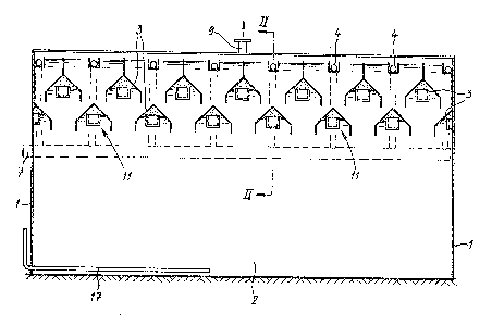
Numéro de la demande Pays / territoire Date
8601120 (Pays-Bas (Royaume des)) 1986-05-01

Abrégés

Abrégé anglais


ABSTRACT
To avoid considerable vertical and horizontal flows in
the settler formed by gas collection hoods, of the upflow
anaerobic sludge blanket (U.A.S.B.) reactor, each gas collection
hood debouches at one or two ends into a gas collection chamber
via one or more openings, the upper boundary of said openings
being situated below the inside surface of the projection or the
top of the hood concerned. The gas collection hoods are
situated immediately below the level of the effluent discharge
and the depth of the settler is shallow. As a result of the
decrease in pressure only a few gas bubbles are consequently
liberated and the settling of the sludge is not appreciably
disturbed.

Revendications

Note : Les revendications sont présentées dans la langue officielle dans laquelle elles ont été soumises.


WE CLAIM:
1. Equipment for the anaerobic purification of waste water comprising a reactor with
fermentation section, a settler provided above said fermentation section, means for feeding
waste water to the fermentation section, and means provided at the top of or above the settler
for the discharge of purified water, which settler comprises at least one tier of gas collection
hoods, characterized in that each gas collection hood includes a gas discharge means located
at at least one end thereof, each gas discharge means including, in communication, an inlet
means for gas to be discharge open to said hood and located below the top of said hood,
and an outlet means for gas to be discharged having an upper boundary located below said
inlet means, so as to prevent liquid from flowing into said gas discharge means.
2. Equipment according to claim 1, additionally comprising a gas collection chamber in
communication with said outlet for gas to be discharged.
3. Equipment according to claim 2, wherein said discharge means comprises a receptacle
including a plurality of walls, one said wall including said inlet means for gas to be
discharged, and an other said wall including said outlet means for gas to be discharged.
4. Equipment according to claim 3, wherein said inlet means is located in a wall facing
the top of the hood or in a wall facing the length of the hood, and said outlet means is
located in a wall facing the gas collection chamber.
-5-

Description

Note : Les descriptions sont présentées dans la langue officielle dans laquelle elles ont été soumises.


~3~.15~
The invention relates to equipment for the anaerobic
pur;fication of waste water, comprising a reactor with a
fermentation section, a settler provided above sa;d fermen-
tation section, means for feeding waste ~ater to the fermen-
tation section, and means provided at the top of or abovethe settler for the discharge of pUf ified ~ater, which
settler comprises at least one tier of gas collection hoods.
Such equipment is in practice often described by the
term U.A.S.~. reactor, U.A.S.B. standing for "up~low anaero-
bic sludge blanket". Known equipment of this type oftenhas two tiers of gas collection hoods, each hood of the
lowermost tier being connected, for example, by an inclined
p;pe to a hood of the uppermost t;er. Ho~ever, a settler
with a single tier of gas collection hoods is also possible.
All the gas collected flows from the gas collection hoods of
the lowermost tier or the single tier directly to a gas
discharge pipe ~hich is connected~ for example, to a gaso-
meter. This known type of anaerobic purification system
may exhibit ~he disadvantage that as a result of turbulænce,
sludge and water are incompletely separated from each other
in the settler, ~h;ch has a detrimental effect on the
efficiency of the systemD Said turbulence is due, ;nter
alia, to upward fLows be;ng produced in the settler due to
miniscule small gas bubbles. These gas bubbles are produced
as a result of it being possible for the ~ater at greater
depth to have more gas in solu~ion than water at the surface.
During up~ard flo~ this supersaturation of gas ~ill emerge
from the uater in the form of small bubbles. Once such a
flow has been produced, it maintains itself as a result of
the gas lift starting to operate and transporting water from
greater depths. This has the result that large ver~ical and
horizon~al flo~s are produced in the settler.
The object of the invention is to avoid this dis-
advantage to a substantial e~tent and provide an anaerobic
~' ~
.
,

~3~
pur;f;cation system of the type mentioned in the introduction
in ~hich at least the ~one near the means for dischar~ing
purified water, usually constructed as overflou troughs, is
largely free of turbulence and the separation between sludge
and water is therefore improved.
According to the invention, the equipment for this
purpose is characterized ;n that each gas collection hood
debouches at at least one end into a gas collection chamber
via one or more openings, the upper boundary of said openings
being situated below the inside surface of the projection
or the top of the hood concerned.
As a result of using the invention, thP only per~itted
flow is the flow of effluent~ aecause the gas coLlection
hoods are placed i~mediately below the level of the effluent
discharge and the depth of the total settler is low, at most
only a fe~ gas bubbles are liberated as a result of the
decrease in pressure and the settling of the sludge cannot
be appreciably disturbed.
Preferably, liquid-retaining ~eans which prevent
~iquid flowing into the gas collection chamber during oPera-
tion are provided near said openings.
There are variows possibilities for constructing the
liquid-retaining ~eans, for exanple, valves ~hich respond
to gas pressure or liquid level. With a view to simplicity
and operational reliability it is, however, preferable that
said means consist of a receptacle with one or more openings
in the rear wall facing the gas collection cha~ber and one
or more openings in the upper or front wall~ the liquid
overflo~ level of said upper or front ~all being situated
above the ~op edge of the opening(s) in the rear wall.
The invention will no~ be exPla;ned in more detail
on the basis of the figures which show an exemp(ary embodi-
ment.
Figure 1 shows a cross section through the reactor
along the line I-I in Figure 2.
figure 2 shows a section along the line II-II ;n
Figure 1.
Figure 3 shows a perspective view of a gas collection

~3~
~ .
- 3 -
hood at the place where the latter debouches into the gas
collection chamber, a part being imagined as broken away.
The equipment shown comprises a reactor 1, the lower-
most part of ~hich forms the fermentation section 2, while
above said section 2 there is provided a settler in the form
of t~o tiers of gas collection hoods 3. Above the upper-
most tier of hoods 3 there is situated a number of overflow
troughs 4 with V-shaped cutouts 5 in the side walls. These
effluent troughs are intended to collect purified water.
from each overflow trough 4 there runs a discharge pipe 6
to a discharge collection point 7.
Each gas collection hood 3 debouches at one end into
a gas collection chamber 8 which is connected to a gas
discharge 9. At the position of this debouchment a small
receptacle 11 is provided consisting of a continuous front
wall 12, continuous side wall 13 and a continuous base 14.
The rear surface and the top surface of the small receptacles
are open or provided with openings, the upper edge of the
opening or openings in the rear surface being indicated by
20 15 and the upper edge of the front wall 1Z by 16. It will
be explained later why it is of importance that 16 is higher
than 15.
A feed pipe 17 for waste water debouches into the
fermentation section 2.
The operation of the equipment is as follows:
A layer of anaerobic sludge is provided on the bottom
of the fermentation section 2. Waste water is fed v;a the
pipe 17 and distributed over the bottom of the container 1
by means known per se which are not drawn. As a result of
anaerobic fermentation, organic material is converted, inter
alia, into fermentation gas (methane) which partly dissolves
in the water and partly rises in the form of gas bubbles.
The liquid level rises as a result of the influent fed in
until said level reaches the top edge of the effluent
troughs 4 and said troughs are f;lled with a current of
purified water. Said purified water is discharged via the
pipes 6 and 7~
The rising gas is collected in the gas collection

~q`
-- 4
hoods 3 and flows out of said hoods via the open top surface
and open rear surface of the small receptacles 11 into the
gas collection chamber 8 and is discharged therefrom via
pipe 9. Because the top edge 16 of the front wall 12 is
S higher than the top edge 15 of the opening(s3 in the rear
surface of the small receptacles, liquid cannot flow into
the gas collection chamber, since the gas pressure in each
hood 3 will force the liquid level 18 back to just below the
level of the top edge 16 of the front wall 12, after which
gas can escape to the chamber 8. The gas pressure continues
to be maintained at a virtually constant value which is suf-
ficient to hold the liquid level below the edge 16. In fact,
the receptacles art as locks for preventing liquid flowing
into the gas collection chamber 8.
It will be clear that cther constructions are con-
ceivable for said locks (liquid-retaining means) such as a
non-return valve responding to pressure or a valve regulated
by liquid level. If the small receptacles 11 are chosen,
and that is possible because of simplicity and operational
reliability~ it is also possible for ~he orifices for the
gas to be situated at other positions. For example, the top
surface of the small receptacles is closed and one or more
openings are prov;ded in the front wall 12. Instead of an
open rear ~all of the small receptacles, a number of openings
may be chosen in an otherwise continuous rear wall~ However,
the liquid overflow edge of the opening(s) in `the front wall
should be higher than the top edge of the opening(s) in the
rear wall.
Instead of a common gas collection chamber 8 each
hood can have its own gas discharge. Other mod;fications
2re also possible within the scope of the invention~ -
,,
,~ , .

Dessin représentatif
Une figure unique qui représente un dessin illustrant l'invention.
États administratifs

2024-08-01 : Dans le cadre de la transition vers les Brevets de nouvelle génération (BNG), la base de données sur les brevets canadiens (BDBC) contient désormais un Historique d'événement plus détaillé, qui reproduit le Journal des événements de notre nouvelle solution interne.

Veuillez noter que les événements débutant par « Inactive : » se réfèrent à des événements qui ne sont plus utilisés dans notre nouvelle solution interne.

Pour une meilleure compréhension de l'état de la demande ou brevet qui figure sur cette page, la rubrique Mise en garde , et les descriptions de Brevet , Historique d'événement , Taxes périodiques et Historique des paiements devraient être consultées.

Historique d'événement

Description Date
Inactive : Périmé (brevet sous l'ancienne loi) date de péremption possible la plus tardive 2009-07-21
Inactive : Lettre officielle 2007-01-11
Inactive : Paiement correctif - art.78.6 Loi 2006-12-18
Inactive : CIB de MCD 2006-03-11
Inactive : Grandeur de l'entité changée 2002-07-04
Accordé par délivrance 1992-07-21

Historique d'abandonnement

Il n'y a pas d'historique d'abandonnement

Historique des taxes

Type de taxes Anniversaire Échéance Date payée
TM (catégorie 1, 5e anniv.) - petite 1997-07-21 1997-06-25
TM (catégorie 1, 6e anniv.) - petite 1998-07-21 1998-06-25
TM (catégorie 1, 7e anniv.) - petite 1999-07-21 1999-06-25
TM (catégorie 1, 8e anniv.) - générale 2000-07-21 2000-06-28
TM (catégorie 1, 9e anniv.) - générale 2001-07-23 2001-06-26
TM (catégorie 1, 10e anniv.) - générale 2002-07-22 2002-06-20
TM (catégorie 1, 11e anniv.) - générale 2003-07-21 2003-06-23
TM (catégorie 1, 12e anniv.) - générale 2004-07-21 2004-07-19
TM (catégorie 1, 13e anniv.) - générale 2005-07-21 2005-07-12
TM (catégorie 1, 14e anniv.) - générale 2006-07-21 2006-07-17
2006-07-17
2006-12-18
TM (catégorie 1, 15e anniv.) - générale 2007-07-23 2007-06-26
TM (catégorie 1, 16e anniv.) - générale 2008-07-21 2008-06-26
Titulaires au dossier

Les titulaires actuels et antérieures au dossier sont affichés en ordre alphabétique.

Titulaires actuels au dossier
PAQUES B.V.
Titulaires antérieures au dossier
SJOERD HUBERTUS JOZEF VELLINGA
Les propriétaires antérieurs qui ne figurent pas dans la liste des « Propriétaires au dossier » apparaîtront dans d'autres documents au dossier.
Documents

Pour visionner les fichiers sélectionnés, entrer le code reCAPTCHA :


Pour visualiser une image, cliquer sur un lien dans la colonne description du document (Temporairement non-disponible). Pour télécharger l'image (les images), cliquer l'une ou plusieurs cases à cocher dans la première colonne et ensuite cliquer sur le bouton "Télécharger sélection en format PDF (archive Zip)" ou le bouton "Télécharger sélection (en un fichier PDF fusionné)".

Liste des documents de brevet publiés et non publiés sur la BDBC .

Si vous avez des difficultés à accéder au contenu, veuillez communiquer avec le Centre de services à la clientèle au 1-866-997-1936, ou envoyer un courriel au Centre de service à la clientèle de l'OPIC.

({010=Tous les documents, 020=Au moment du dépôt, 030=Au moment de la mise à la disponibilité du public, 040=À la délivrance, 050=Examen, 060=Correspondance reçue, 070=Divers, 080=Correspondance envoyée, 090=Paiement})


Description du
Document 
Date
(aaaa-mm-jj) 
Nombre de pages   Taille de l'image (Ko) 
Abrégé 1993-12-14 1 18
Dessins 1993-12-14 2 60
Revendications 1993-12-14 1 34
Description 1993-12-14 4 155
Dessin représentatif 2000-08-24 1 17
Taxes 2003-06-22 1 22
Taxes 1997-06-24 1 40
Taxes 2001-06-25 1 33
Taxes 2002-06-19 1 32
Taxes 1998-06-24 1 39
Taxes 1999-06-24 1 37
Taxes 2000-06-27 1 34
Taxes 2004-07-18 1 27
Taxes 2005-07-11 1 23
Correspondance 2005-07-11 1 23
Correspondance 2007-01-10 1 14
Taxes 1996-07-08 1 39
Taxes 1995-07-09 1 37
Taxes 1994-06-21 1 42