Note: Descriptions are shown in the official language in which they were submitted.
ENGINE GOVERNOR FRICTION DAMPER AND METHOD
TECHNICAL FIELD
The present invention relates to engines, in
particular engines for use in power generator sets.
More specifically, the invention concerns governor
systems for such engines, and the provision of a damper
mechanism to generally limit governor over~compensation
and inhi~it searching.
~ACKGROUWD OF THE INVENTION
Conventional generator sets have found a wide
variety of uses. Typically, a generator set comprises
an engine in association with a generator or generator
mechanism, used to provide electrical power. Such
systems are used, for example, to provide emergency
power in homes and offices. Portable units are used to
provide electrical power at work stations in the field
and for recreational vehicles and the like.
Generally, the engine i5 spark-ignited, uti-
lizing gasoline, natural gas, propane, diesel, or simi-
lar fuel. The engine is typically set to run at a
preferred speed, usually defined in terms of the revolu-
tions per minute (rpm) of the engine driveshaft. This
speed is ordinarily determined by the rate at which the
engaged generator must be driven, to efficiently produce
power during a typical load.
During use, the load on the engine ~ay vary
considerably. This may occur as power drain on the
generator is varied. For example, a load variation will
occur as a power tool or appliance is turned on or o~f.
I~ a heavier load is placed on the engine, the
engine will tend to slow down. The engine governor
system or mechanism provides for a continual adjustment
in engine speed in response to the load variations, to
maintain a relatively constant engine speed. Generally
this is accomplished through an adjustment in a throttle
of the engine, i.e. air or fuel flow from or through the
~3~ 3`~
carburetor. Typically this is accomplished through
adjustment of a butterfly valve or throttle plate. That
is, should a greater load be placed on the engine, the
throttle is adjusted somewhat in response to the con-
comitant decrease in rpm, allowing the engine to speed
up. On the other hand, should a load suddenly be taken
off an engine, the throttle is adjusted in an opposite
manner, in response to the rpm surge, to slow the engine
down.
The typical governor system includes a sensor
mechanism which detects, either direct~y or indirectly,
the rotation speed of the engine driveshaft or crank
shaft. Through conventional governor linkage mechanisms
including a governor member, the sensor typically com-
municates with a throttle control. A typical governor
linkage mechanism includes a governor arm, as a governor
member. The governor arm is linked to another governor
member, a governor rod, which provides mechanical com-
munication with the throttle control. In many conven-
tional systems this occurs through mechanical connection
~o a pivotable rod on which a throttle plate is mounted.
Rotation of the pivotable rod selectively orients the
throttle plate to increase or decrease engine speed.
Such systems are well-known and will not be
described in detail herein. However, generally, should
the engine speed change, the governor sensor, in
response to the change in engine speed, moves the gover-
nor member. Movement of the governor member typically
causes controlled adjustment of the throttle, generally
through a predicted pivoting of the throttle plate to
adjust the engine speed back toward a desired norm.
Since the very earliest developments of gover-
nor systems, there have been problems of huntîng or
searching and over-compensationO That is, while
io ` t
.~3~
attempting to return the engine speed to the normal,
desired, speed, the governor usually over-compensates.
As a result, the engine may speed up and slow down a
number of times, before ;t finds the correct speed.
This is typically referred to as "hunting" or
"searching".
Searching is a problem, since it may lead to
undesired power fluctuations and inefficient utilization
of fuel. In the past, attempts to control hunting or
searching have generally involved efforts to reduce to a
minimum the amount of mechanical friction present in
the governor linkage mechanism. This has generally led
to an improvement in governor performance, partially due
to a limitation in the amount that any given movable
mechanical joint can unpredictably "stick". However,
even reduced friction systems still undergo a substan-
tial amount of undesired searching or hunting.
What has been needed has been a system and
method for the reduction and/or control of undesired
over-compensation leading to hunting or searching.
:~3~
OBJECTS OF THE INVENTION
Therefore, the objects of the present inven-
tion are: to provide a method of reducing searching or
hunting in governor controlled engine syst~ms; to pro-
vide such a method comprising the utilization of a fric
tion damper to limit the governor movement which causes
over-compensation, to provide such a method which
comprises the placement of a friction damper mechanism
on a linkage in a governor mechanism; to provide such a
method including placement of the damper mechanism at a
linkage between a governor mechanism and a throttle
control; to provide such a damper mechanism comprising a
friction washer member operating under applied pressure
from a biasing member to generate resistance to movement
of an engine throttle control arm, due to the applied
pressure; and, to provide such a damper mechanism which
is relatively inexpensive to produce, easy to assemble
and which is particularly well adapted for the proposed
usages thereof. It is another object of this invention
to provide a damper mechanism and method readily adap-
table to control searching and over-compensation in a
variety of conventional governor systems, with only a
few modifications being necessary.
Other objects and advantages of this invention
will become apparent from the following d0scriptions,
taken in conjunction with the accompanying drawings
wherein are set forth by way of illustration and example
certain embodiments of the present invention.
OS-&~
SUMMARY OF THE INVENTION
According to the invention a riction damper
is placed in a governor system, to resist movement of a
portion of the governor mechanism and dampen throttle
adjustment in response to changes in speed of the engine
detected by a governor sensing mechanism. The mechanism
generally comprises a friction damper, which resists
adjustment of the governor mechanism, and thus the
throttle, a certain, selected, amount. Otherwise, the
damper per~its the governor system to adjust in a more
or less conventional manner. It has been found that
through the introduction of such a friction damper
system, a substantial reduction in searching or hunting
will occur.
The preferred friction damper mechanism
according to the present invention is positioned at a
juncture or linkage between a governor member and a
mechanism which actuates throttle adjustment.
Generally, the throttle adjustment mechanism comprises a
link arm or crank arm pivotally mounted by an axle. The
crank arm rotatably engages a governor rod, which
generally linearly moves with respect to changes in
engine speed detected by a governor sensing mechanism.
Thus, as the governor rod moves, the crank arm is
pivoted. Generally, the crank arm causes rotation of a
shaft on which a throttle plate is mounted, to adjust
the throttle and change engine speed.
In a preferred application of the present
invention, the governor rod is circular in cross-
section, with a lateral extension on one end which enga-
ges an aperture in the crank arm. The damper mechanism
of the preferred embodiment comprises utilization of
friction washer means mounted at the en~agement between
the governor rod and the crank arm. The friction washer
~3~
means includes at least one washer biased plate against
the crank arm and an extension or projection on the
governor rod, to squeeze the linkage. As a result, a
friction system is created to resist pivoting of the
crank arm relative to the governor rod. By varying the
amount of biasing pressure on the washer plate, a
selected force can be created to appropriately dampen
the system, while still permitting selected engine speed
adjustment. The preferred damper mechanism includes a
pair of washer plates with the crank arm positioned
therebetween.
The drawings constitute a part of this speci-
fication, and include exemplary embodiments of the pre-
sent invention, while illustrating various objects and
features thereof. In some instances, relative material
thicknesses an component sizes may be shown exaggerated,
to facilitate an understanding of the invention.
BRIEF DESCRIPTION
OF THE DRAWINGS
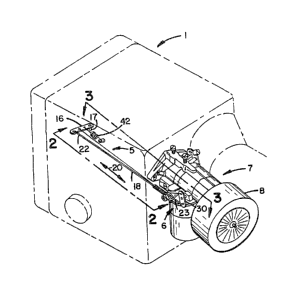
Fig. 1 is a fragmentary perspective view of
an engine/generator set modified according to the present
invention to include a friction damper mechanism in
association with a governor system thereof; many of the
components of the engine/generator set, not of immadiate
concern to an understanding of the friction damper
mechanism, being shown in phantom lines.
Fig. 2 comprises an enlarged, fragmentary,
side elevational view of a portion of the invention
depicted in Fig. 1, taken generally from the point of
view of line 2-2.
~3~ 3~
Fig. 3 comprises an enlarged, fragmentary top
plan view of a portion of the arrangement shown in Fig.
1, taken generally from the perspective of line 3-3,
Fig. 2, with portions broken away to show internal
detail.
Fig. ~ i5 an exploded, fragmentary, perspec-
tive view of a portion of the invention depicted in Fig.
1, showing components of a friction damper mechanism
according to the present invention.
Fig. 5 is a graphic representation of
searching in a prior art system, under 1/4 rated load.
Fig. 6 is a graphic representation of
searching in a prior art system, under 1/2 rated load.
Fig. 7 is a graphic representation
illustrating damping of searching in a system according
to the present invention, and under 1/4 rated load.
Fig. 8 is a graphic representation
illustrating a damping of search;ng in a system
according to the present invention and under 1/2 rated
load.
DETAILED DESCRIPTION
OF THE PREFERRED EMBODIMENT
As required, detailed embodiments of the pre-
sent invention are disclosed herein; however, it is to
be understood that the disclosed embodiments are merely
exemplary of the invention, which may be embodied in
various forms. Therefore, speciic structural and func-
tional details disclosed herein are not to be
interpreted as limiting, but rather as a basis for the
claims and as a representative basis for ~eaching one
skilled in the art to variously employ the present
5~
invention in virtually any appropriately detailed struc-
ture.
The reference numeral 1, Fig. 1, generally
designates an engine/generator set modified according to
the present invention. ~he present invention may be
utili7ed in association with a variety of systems
involving governor-controlled engines, however it is
particularly suited for use in engine/generator sets for
electrical power production~ ~he engine/generator set 1
may be of a variety of types and manufactures.
Generally, the engine comprises an internal combustion
engine, i.e., a spark-ignited engine, which utilizes
gasoline, propane, natural gas, diesel fuel or similar
fuels. As the engine is operated, a driveshaft is
rotated, in a conventional manner, to drive the genera-
tor portion of the set 1. The generator, in a conven-
tional manner, provides electrial power. It will be
understood that the engine/generator set 1 may be por-
table, however there is no re~uirement that it be so.
The reference numeral 5, Fig. 1, generally
designates the governor system, which provides mechani-
cal communication between portions of the engine/
generator set 1 not detailed, and portions of a throttle
control system 6, Fig. 1. Typically, the throttle
control system 6 is part of, or is closely associated
with, a carburetor system 7.
In a conventional manner, the carburetor
system 7 provides for a controlled mixing of fuel and
air and introduction of the mixture into the engine.
Air is generally introdu¢ed into the system via air
filter 8, Fig. 1. The engine includes a throttle
assembly 9, which may be of a conventional type,
controlling engine speed by adjustment in orientation of
a butterfly valve or throttle plate 10.
~3~i,3~3
Referring to Fig. 3, the throttle plate 10 of
the preferred embodiment is pivotally mounted by rod ll.
As rod ll is pivoted, the throttle plate lO re-orients
to open or close, selectively, passageway 13, resulting
in selective control and adjustment of engine speed.
By a conventional means or systeml not
detailed, the governor system 5 responds to changes in
engine speed to cause an automatic adjustment in the
throttle assembly 9, for the preferred embodiment by
rotation of the throttle rod ll to pivot the throttle
plate 10. In general, this involves utili2ation of a
governor sensor system or mechanism not detailed, so
that the governor system 5 appropriately responds to
changss in engine speed. A typical mechanism for such a
sensor system is a fly weight ball or ~lyball system,
mounted on or in association with the engine crankshaft
or driveshaft. Such a system operates with respect to
rotational forces, to move a governor member such as
pivotable governor arm 16, predict:ably, in response to
variations in engine speed.
The governor member or arm 16, of the pre-
erred embodiment, is mounted on or in association with
the engine block to pivot about an axis defined by axle
17, again controllably and predictably in response to
ehanges in engine speed detected by the governor sensing
system. For the preferred embodiment described and
shown, the governor arm 16 is mounted on a substantially
vertical axle 17, however a variety of physical arrange-
ments can be used.
For the embodiment of Fig. 1, arm 16 provides
a link to the remainder of the governor link mechanism
including another governor member, preferably governor
S163~
-- 10 --
rod 18. As arm 16 pivots about the axis defined by axle
17, governor rod 18 is driven substantially longitudi-
nally, in the directions generally shown by double-
headed arrow 20, Fig. 1.
For the preferred embodiment, governor rod 18
is circular in cross-section and comprises an elongate
extension of material such as steel or aluminum.
Governor rod 18 includes first and second end portions
22 and 23, respectively.
Referring to Figs. 2 and 3, the first end por-
tion 22 includes means for engaging governor arm 16. A
preferred method of engagement is by the passage of a
twist or bend 25 in end portion 22 through an aperature
26 in governor arm 16. By this conventional arrange-
ment, a secure, yet pivotable, engagement is provided
between fla~ elongate governor arm 16 and round elongate
governor rod 18.
The second end portion 23 of the governor rod
18 includes means for engagement with the throttle
control system 6. Referring to Figs. 1 and 2, the
throttle pivot rod 11 includes a ~rank arm 30 non-
pivotally mounted thereon. The crank arm 30 includes an
extension 31, Fig. 4, with an aperture 3~ therethrough.
The second end 23 of the preferred governor rod 18
comprises a bend 35 defining a lateral extension or
projection 36 and tip 37 which extend through aperture
32, Fig. 4. Referring to Fig. 2, as rod 18 moves in
the directions of double-headed arrow 20, crank arm 30
is pivoted, rotating axle 11 to manipulate throttle
plate 10.
Main governor spring 41 operates in a conven-
tional manner to maintain a desired physical orientation
of the overall governor throttle link system assembly,
which comprises governor arm 16, governor rod 18 and
~3~
crank arm 30. Generally, the spring ~1 operates in
opposition to the governor sensor, to maintain a steady
engine rate and prevent the system from going into wide-
open throttle. It will be understood that crank arm 30
and axle 11 need not provide for a direct mechanical
conection between governor rGd 18 and the throttle plate
10. Rather, further mechanical linkages may be used.
As thus far described, the system comprises a
conventional governor system or assembly. The strip
charts illustrated in Figs. 5 and 6 represent operation
of such a system, and searching or hunting whi¢h may
result. Referring to Fig. 5:
The chart of Fig. 5 illustrates hunting or
searching of an engine which has been set for a constant
speed, in an engine/generator set; the set having a load
applied thereto. For example, the engine/generator set
may comprise a six kilowatt generator, with the engine
speed sett desirably, at about 1,800 rpm. The strip of
Fig. 5 generally shows the behavior of the system, when
placed under about one quarter load, i.e., for a 6 kw
rating a 1.5 kw load~ The space between each vertical
line represents about one seeond of passed time, the
space between each horizontal line representing about a
rpm change in engine speed. For the example
illustrated in Fig. 5, within the first two seconds
after an applied one quarter of rated load, the engine
speed dropped from 1,800 rpm to about 1,620 rpm. The
governor system then over-compensated within the next
second or so, to bring the engine speed to about 1,860
rpm. The governor system then over-compensated to the
negative, bringing the engine speed to about 1,680 rpm
at about three seconds. As is understood by reference
to Fig. ~, generally searching or hunting resulted in a
passage of the engine speed through a plurality of
~L3~3~3
maxima and minima, for the example about 8 maxima and 8
minima~ until a ralatively steady speed was obtained.
Fig. 6 generally represents an undampened
system in which about one-half of the rated load was
applied. For example, if the generator rated load was
about 6 kw, about 3 kw of power drain was applied.
Again, it is seen that the governor hunted or searched,
in response to the power drain, to find the appropriate
engine speed.
Fig. 7 represents a system generally analogous
to Fig. 5, but including a friction damper according to
the present invention. It is readily seen from Fig. 7
that under a strain of one-quarter of the rated load,
the governor assembly relatively rapidly returned the
engine to approximately the set speed, with passage
through only relatively few maxima and minima before a
steady engine speed was obtained.
Similarly, Fig. 8 is analogous to Fig. 6, but
with the introduction of a damper system according to
the present invention into the mechanism. It is readily
seen that under one-half of the rated load, the governor
assembly rapidly returned the engine speed to the rated
level, again with passage through only relatively few
maxima and minima.
The preferred friction damper according to the
present invention is introduced into the system at the
joint between the governor rod 18 and the crank arm 30
that controls adjustment of the throttle 6. This is
readily understood by reference to Fig. 4.
In Fig. 4, a friction washer plate or member
mechanism is illustrated. The mechanism includes a
first washer member 44 mounted upon extension 36 in rod
18, to press against or toward the crank arm 30.
~3i~S~
- 13
Friction washer member 44 is biased toward the crank arm
30 and a portion of the governor rod 18, specifieally
bend 35, under spring pressure, to squeeze the crank arm
30 between the washer 44 and bend 35 and, provide
resistance to pivoting of the end portion 23 of the
governor rod 18 with respect to the end 31 of the crank
arm 30. It will be understood that if there is
resistance to this pivoting, there is generally a
damping of crank arm 30 movement. In the preferred
embodiment, the friction washer mechanism includes two
friction washer members 44 and 45, positioned on oppo-
site sides of crank arm 30.
Biasing of the friction washer members 44 and
45 toward one another, to generate desired friction,
will be understood by reference to Figs. 3 and 4.
Generally, washer member 45 presses up against bend 35.
Washer member 44 is positioned on the opposite side of
crank arm 30 and is biased thereas~ainst by a biasing
means comprising spring 50. Spring 50 is maintained in
position by a conventional retainer member, such as a
clip 51 which can mate with a groove 52 in rod 18.
While a variety of spring mechanisms may be
utilized, it has been found that a conventional
stainless steel spring applying between one and three
pounds, and preferably about two pounds, of force
against friction washer 44, is desired for most applica-
tions. It will also be understood that friction washer
members 44 and 45 may be constructed from a variety of
materials. Conventional copper washers have been found
to operate quite effectively.
The preferred embodiment has been illustrated
with a spring directing force toward the major portion
of the governor rod. It will be understood that in some
applications an opposite arrangement may be desired.
- 14 -
Also, for simplicity the preferred embodiment i5
illustrated with friction being genera~ced between a bend
in the governor rod and a washer member ~4, with the
crank arm therebetween. In alternate embodiments, the
governor rod may include a projection such as a post or
flange thereon, or similar structure, against which or
toward which the washer member and biasing means presses
the crank arm. It will be understood that as a result
of the bend, the main portion of the governor rod itself
provides a projection against which pressure is
directed, to provide the desired friction.
From the above descriptions, it will be
understood that the present invention generally includes
a method for the reduction of hunting or searching in a
governor controlled engine/generator set through the
introduction o~ a friction damper into the system, most
preferably at a connection between a governor mechanism
and a throttle control. A specific preferred arrange-
ment utilizing a governor rod with a bend therein, a
pair of friction washers, a compr~3ssion spring and a
crank arm is disclosed. As a result of the introduction
vf the friction damper mechanism into a conventional
governor assemblyr searching is reduced, Figs. 7 and 8,
since throttle adjustment is inhibited somewhat. The
present invention may be installed with appropriate
modifications in a variety of conventional governor
systems, to control over-compensation and searching.
It is to be understood that while certain
embodiments of the present invention have been
illustrated and described, the invention is not to be
limited to the specific forms or arrangement of parts
herein described and shown.