Note: Descriptions are shown in the official language in which they were submitted.
~36~.L57~i~
THIS INVENTION relates to a high temperature
rechargeable electrochemical power storage cell; to a
molten salt electrolyte for such cell; and to a method
of operation of such cell.
According to one aspect of the invention there is
provided a high temperature rechargeable
electrochemical power storage cell which comprises:
an alkali metal anode which is molten at the
operating temperature of the cell;
an alkali metal aluminium halide molten salt
electrolyte whose alkali metal is the same as that of
the anode, whose halide ions include chloride ions and
which is molten at the operating temperature of the
cell;
: 15 a cathode whose active cathode material comprises
at least one member of the group of transition metals
consisting of Fe, Ni, Co, Cr and Mn and which is in
contact with said electrolyte; and
between the anode and electrolyte and separating
them from each other, a separator which is a solid
conductor of ions of the alkali metal of the anode,
the electrolyte containing a dopant which is a member
of the group comprising M2X, MY and MAZ in which M is
.~ the alkali metal of the anode, X is a divalent anion,
.~
. 25 Y is a monovalent anion and Z is a polyvalent anion
with a valency of A, said dopant acting to reduce the
Lewis acidity of the electrolyte~
Thus, the dopant can react with the MAlCl4 in
: accordance with any one of reactions (I) - ( IV~ as
follows: ~
(I) M2X ~ MAlCl4 -~ 2MCl + MAlC12X;
(II) M2X + 2MA1Cl4 ~ 2MCl + M2(Cl3Al-X-AlCl3~:
or
~ (III) MY ~ MAlCl4 } MCl + MAlCl3Y,
: 35 (IV) MAZ ~ M~1C14 ~ MCl + MA~AlC13Z)
, 3~
~3~ii'75~
the products MAlCl2X, M2(Cl3Al-X-AlCl3~ and MAlCl3Y
having a lower Lewis acidity than MAlC14, and the doped
molten salt electrolyte containing M and Al in a M:Al
molar ratio of at least 1:1.
The alkali metal M of the anode and of the molten
salt electrolyte may be Na, the separator being a B-
alumina solid conductor o~ sodium ions. It will be
appreciatedl however, that al~hough the separator will
typically be a ~~alumina [eg B"-alumina~ or nasicon
solid conductor of sodium ions, the invention can
apply equally to cation-exchanged ~aluminas such as
potassium- or lithium-B-aluminas, which are conductors
of potasslum or lithium ions respectively.
In the cell of the present invention, the active
cathode material is conveniently dispersed in an
electrolyte-permeable, electronically conductive
matrix, which has the molten salt electrolyte
impregnated therein. This matrix may be formed of the
transition metal of the cathode in metallic form, or
it may be an intermediate refractory hard metal
compound of the transition metal with a non-metal such
as carbon, silicon, nitrogen, boron or phosphorous.
In the case where M is Na, reactions (I) to (IV)
set forth above can be represented as follows:
(V) NazX + NaAlCl4 ~ 2NaCl + NaAlCl2X;
(VI) Na2X + 2NaAlCl4 ~ 2NaCl + Na2(Cl3Al-X-AlCl3);
(VII) NaY + NaAlCl4 ~ NaCl + NaAlCl3Y; and
(VIII) NaAZ + NaAlCl4 ~ NaCl + NaA(AlCl3Z)
In the case of reactions (II) and (VI) se~ forth
above, the reaction product containing Al and X has an
anion which is a polymer, whose basic structure is as
foll~ws:
~Cl c~)
( \ ,/ )
(Cl ~ 1- X -Al - Cl)
(Cl Cl)
However, longer polymers of the form -A1-X-Al-X-
Al-.... are also possible, and similar polymers can
occur with regard to reaction products of reactions
(IV) and (VIII).
The dopant may comprise at least one member of
the group comprising:
M20;
M2C03;
; M2S04
M2P04;
M2BO4;
M2S3;
MAl02; and
MPO3.
.
As indicated above, M will typically be Na, so that
examples of species falling within the definition of
; M2X are Na2O, Na2C03, Na2SO4, Na2P04, Na2B04 and N 2 3i
and examples of MY are NaAl02 and NaP03. Sodium
late [COONa~2, borax [Na2B4O10] and Na4P2O7 can also
be used. The aforegoing are merely the preferred anion
species, and it will be appreciated that other anions
which contain atoms or groups which are less
electronegative than Cl- and which are capable of
~- displacing Cl form an AlC13 molecule can be used
instead. Where M is Na, the Applicant has found that,
conveniently, the only halide ions in the molten salt
; ~ electrolyte are chloride ions, the dopant being Na2CO3.
s indicated above, MAlCl?X; M2(Cl3Al-X-AlCl~) ~r
polymers thereof; MAlCl3Y; or MA(AlC13Z) or polymers
thereof must have a lower Lewis acidity than MAlCl4. In
(
.
~L3~157~
other words, AlClX~ or (C12Al-X ~lC123 or polymers
thereof; (~lCl3Z) or polymers thereof; or AlCl2Y should
each be a weaker Lewis acid than AlCl3.
The dopant may be present in the molten salt
electrolyte in a proportion of from 2 - 30 mole %,
preferably from 5 - 10 mole %.
~ The invention provides further a molten salt
; electrolyte for a high temperature rechargeable
electrochemical power storage cell containing a dopant
which is a member of the group M2X, MY and MAZ as herein
described.
The invention extends also to a method of combatting
progressive rise in internal resistance of a cell as
herein described, particularly on overcharging, which
method comprises doping the liquid electrolyte of the
cell with a dopant which is a member of the group M2X, MY
and MAZ as herein described.
In the specific case indicated above where the
molten salt electrolyte of the cell comprises essentially
doped sodium aluminium chloride, in which the only halide
ions are chloride ions, this electrolyte, in the absence
of the dopant can be represented as stochiometrically
exact NaAlCl4, in which the ratio of Na:Al ions on a molar
basis is 1:1. This undoped electrolyte can be regarded as
a mixture of an AlC13 Lewis acid and an NaCl Lewis base.
The beta-alumina of the separator used therewith can in
turn be regarded as comprising an Al2O3 Lewis acid and an
Na2O L~wis ~ase, which together form the compound
Na2O.~ 2O3 Accordingly, the NaAlCl~ undoped
electrolyte and the beta-alumina can react together in
accordance with reaction (IX)
(IX~ Na20.11Al203 + NaAlCl4 ~ 2NaCl ~ llAl203 + NaAlC120
,~
. .~,
whereby the beta-alumina can become depleted of NazO,
which is the sodium ion-conducting component thereof,
as the NaAlCl4 electrolyte is more Lewis acidic than
said Na2O.llAl203. ~is is more likely to occur when the AlC1
NaCl mole ratio ~
Similar depletion can take place in analogous
systems employing potassium- or lithium-beta-aluminas
and molten salt electrolytes where the alkali metal is
potassium or lithium, as the case may be~
It follows that incorporation into a molten salt
electrolyte of any dopant M2X, MY or MAZ as defined
above, which tends to reduce the Lewis acidity of the
molten salt electrolyte, will tend to reduce the
likelihood that reactions such as reaction (IX) will
take place. Put differently, if an MAlC14 electrolyte
is regarded as comprising M~ cations and AlCl4 anions,
which anions exist in equilibrium with Cl anions and
AlCl~ Lewis acid molecules in terms of the equilibrium
reaction (X);
(X) AlCl ~ Cl ~ AlCl
4 ~ - 3~
then any dopant which drives this equilibrium to the
le~t and reduces the concentration of free AlCl3 in the
electrolyte, is desirable.
From reactions ~I), (II)~ (III) or (IV) above,
addin~ the dopant M2X, MY or MAZ to MAlCl4 will produce
MAlCl2X; or M2(Cl3Al-X-AlCl3) or polymers thereof;
MAlCl3Y; or MA (AlCl3Z) or polymers thereof, the anions
o~ which respectively are (AlCl2X)~ (Cl3Al-X-AlCl3) or
like polymeric anions; (AlCl3~) ; or (AlC13Z) n or like
polymeric anions, which exist in equilibrium together
with Cl anions and Lewis acid molecules such as AlClX;
or (Cl2Al-X-AlCl2) or polymers thereof; AlCl2Y; or
AlC12Z or polymers thereof as the case ma~ h~. The
Lewis acid produced must thus be a weaker acid than
AlC13 .
5~
For example, in the case of Na20 as dopant, ~lClX
is AlC10; in the case of Na2P04 as dopant, AlClX is
AlClP04; and in the case of Na2B04 as dopant, AlClX is
AlClB04. AlC10, AlClP04 and AlClB0~ are all weaker
Lewis acids than ~lC13, and adding such dopants thus
reduces the overall AlCl3 concentration, and reduces
the overall Lewis acidity of the molten electrolyte.
This results in a reduced tendency for reactions such
as reaction (IX) above to take place, and consequently
results in a reduced rate and/or degree of Na20
depletion of the beta-alumina separator, which
depletion can be regarded as a form of poisoniny of
the separator.
Naturally the dopant added, ie its nature and the
proportions thereof used, should not have any
undesirable effects on the cell. Thus, it should not
interfere with the basic electrochemical cell reaction
and should not elevate the melting point of the molten
electrolyte unacceptably. In choosing the dopant, it
should be borne in mind that steric factors may play
a part, and use of a dopant having a bulky anion
(bulkier than Cl-) can also contribute beneficially by
resisting any tendency for MAlC12X; or
M2(Cl3Al-X-AlCl3) or polymers thereof; or MAlCl3Y; or
MA (AlC13Z) or polymers thereof to react with
M20.11Al203 at the separator surface in a fashion
analogous to reaction (IX).
Finally, it should be noted that with certain
activ~ cathode materials in accordance with the
present invention such as Fe/FeCl2, certain of the
transition metal chlorides such as FeC12 can, it is
believedl be inactivated in an electrochemical sense
(ie unavailable for electrochemical use) at elevated
temperatures of eg 300C or more. This may arise from
i75i~
their reacting with substances such as MCl or AlCl3
present in the molten electrolyte, to form
electrochemically inactive products (polymers or like
inactive phases). It follQws that any dopant which
will tend to reduce the concentration of AlCl3 in the
molten electrolyte (in favour of AlCl4-) will be
beneficial also from this point of view~
The invention will now be described, with
reference to the following non-limiting Examples and
sch~matic drawings in which:
Fiyure 1 shows a diagrammatic sectional side
elevation of an electrochemical cell in accordance
with the present invention;
Figure 2 shows a diagrammatic sectional side
elevation of a test cell used to test molten salt
electrolytes in accordance with the present invention;
Figures 3 - 6 show plots of voltage [V] against
current [A] in the test cell of Figure 2 for various
molten salt electrolytes in accordance with the
invention;
Figure 7 shows a plot similar to Figures 3 - 6
for a prior art [control] molten salt electrolyte; and
Figures 8 - 11 show plots of charge/discharge
curves of cell voltage [V] against capacity [Ah~ for
cells according to the invention of the type shown in
Figure 1.
EXAMPLE 1 - Mak.inq Do~ed Electrolyte
1,252kg of AlCl3 in finely divided powder
form was thoroughly mixed with 0,548kg of
NaCl. This mixture was heated in a nickel
pot at a temperature held between 250 and
300C for about 18 hours to form a molten
undoped sodium chloroaluminate electrolyte
in which there is a 1:1 molar ratio of NaCl
to AlCl3. Na2C03 dopant was then admixed
into
~3~7~:~
g
the undoped electrolyte (30g of NazCO3 for
each kg of AlCl3 used). The partially doped
electrolyte was then left to react to
equilibriu~ for about 2 hrs at 250-300C,
and aluminium metal powder (about 5g for
each kg of AlCl3 used) was then admixed into
the melt to remove any residual acidic
hydrogen which may have been present in the
AlCl3 starting material and the fully doped
electrolyte left for about lhr at 250-300C
to reach equilibrium.
In this way a doped molten salt electrolyte
(sodium chloroaluminate doped with Na2C03)
was made, suitable for use in cells of the
type hereinabove described having beta-
alumina separators and cathodes (charged)
in the form of FeCl2, NiCl2, CoCl2, CrCl2,
MnCl2 or mixtures of two of more of these
~ transition metal chlorides. The new
: 20 electrolyte has, arising ~rom the
proportions of the AlCl3, NaCl, Na2C03 and
aluminium metal used, a Na:Al ~olar ratio in
the molten salt solution formed of 1:1; and
this requirement can easily be ensured by
providing a slight excess of the NaCl
starting material. By virtue of the use of
the Na2CO3, the doped electrolyte has a lower
Lewis-acidity than a 1:1 molar NaCl:AlCl3
melt (ie NaAlCl4).
This molten salt electrolyte can then be
used in a cell of the. type shown in Figure
1.
In Figure 1 of the drawings, reference
numeral 10 generally designates a high
~L3~
temperature rechargeable electrochemical
cell according to the invention. The cell
comprises a housing 12 divided by a beta-
alumina separator ~4 into an anode
compartment 16 and a cathode compartment 18.
The anode compartment contains molten sodium
active anode material 20 and is provided
with a texminal post/current colllector 22.
The cathode compartment in turn contains the
abovedescribed sodium chloroaluminate molten salt
electrolyte doped with Na2C03 at 24, and is
provided with a terminal post/current collector
26. A cathode 28 is provided in the cathode
compartment and ¢omprises an electronically
conductive electrolyte-permeable porous matrix
saturated with said electrolyte 24, within which
the post 26 is embedded. In its charged state
the cathode 28 contains, dispersed therein and in
contact with the matrix and with the electrolyte
24, one or more of the abovementioned transition
metal chlorides, eg NiCl2 or FeCl2, as active
~ cathode material.
:
Upon discharging of the cell, sodium passes
from the anode 20 through the separator 14
and electrolyte 24 in the ionic form to the
cathode, where the FeC12 is discharged to
iron with the production of NaCl. Upon
subsequent charging the reverse takes place,
with FeC12 being produced at the cathode,
while iron is consumed at the cathode and
ionic sodium passes back through the
electrolyte 24 and separator 14 to the
anode, where it receives electrons to form
;;~ molten sodium.
~3L3~
11
It will thus be appreciated that, if there
is a 1:1 molar ratio of Ma:Al in the
electrolyte in the fully charged state of
the ce]l, this ratio will be maintained
during discharging because discharging of
the cell leads to production of NaCl in
solid form in contact with the electrolyte
24, so that said ratio can never be reduced
to a value less than 1:1 and the electrolyte
will never become acidic. Nevertheless, as
a safety precaution, a small proportion of
axcess NaCl may be provided in the cathode
in the fully charged state of the cell,
dispersed in finely divided form in the
cathode matrix, to guard against acidity in
the electrolyte 24.
EXAMPLE 2 - Electrolyte Test
Various electrolytes were made in accordance
with the invention. In each case the dopant
was employed in a concentration of 3% by
mass. The dopants tested were as follows:
sodium carbonate;
sodium oxalate [(COONa)2- an oxide
donor];
sodium pyrophosphate [Na4P207- a so-
called Lux-Flood acid]; and
borax [Na2B40l0 - the conjugate
base of a so~called Lux-Flood
acid].
It is to be emphasized that no attempt was
made to optimize the concentration of dopant
in the doped electrolytes and routine
experimentation will be required to
determine the best concentration of dopant
for a particular cell, and indeed the best
dopant for use in a particular cell.
,~
~3~5~
12
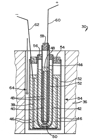
With reference to Figure 2, the test cell
used is designated 30 and had a cylindrical
housing in the form of a glass beaker 32
shown located in an upright condition in a
passage 34 in a furnace 36. A hollow
cylindrical source/sink 38 for sodium
cations is shown resting concentrically on
the floor of the beaker 32. The composit.ion
of this source/sink 38 will be described
hereunder. A further sol~rce/sink 40 is
arranged concentrically within the
source/sink 38.
Two ~"-alumina tubes are shown mounted
inside the source/sink 38, namely an outer
~"-alumina tube 42, located concentrically
in the source/sink 38 and resting on the
floor of the beaker 32, and an inner ~"-
alumina tube 44 located concentrically
within the tube 42. The source/sink 40 is
also in the *orm of a hollow cylinder and
has the same composition, depending on its
state of charge as emerges hereunder, as the
source/sink 38. The source/sink 40 is
located in the tube 44 resting on the bottom
~hereof and spaced radially inwardly from
the cylindrical wall of the tube 44. Molten
salt electrolyte 46 is shown occupying the
interior of the beaker 32, to a depth
sufficient to immerse the source/sink 3a
therein. The tube 44 similarly contains
molten salt electrolyte 48 sufficient to
~ immerse the source/sink 40. The lower end
:~ of the tube 44 is supported above the bottom
: of the tube 42 by an electronically
insulating ~-alumina spacer 50, and the tube
42 contains molten salt electrolyte 52,
which surrounds the lower part of the tube
44. The
~3~575~
13
level of the electrolyte 48 is above the level of
the electrolyte 52, which is in turn above the
level of the electrolyte 46.
The top of the beaker 32 is closed by an annular
Kaowool ceramic wool plug 54 which surrounds the
top of the tube 42. The top of the tube 42 is in
turn closed by an annular Kaowool plug 56 which
surrounds the tube 44. Finally, the top of the
tube 44 is closed by a Kaowool plug 58.
Cell terminals 60 and 62 respectively extend
through the plug 58 into contact with the
source/sink 40 and through the plug 54 into
contact with the source/sink 38. A temperature-
; monitoring thermocouple is shown at 64, in the
passage 34 outside the beaker 32. The cell 30 was
assembled, loaded and operated in a glove box
[not shown] under a dry nitroyen atmosphere.
The source/sinks 38 and 49 were formed in similar
ashion from porous sintered nickel cylinders.
These cylinders were impr egnat ed with NaCl by
dipping into saturated aqueous NaCl solutions and
dried. The nickel of the source/sink 38 was then
chlorinated electrochemically according to the
reaction:
: . .
Ni ~ 2NaCl ~ NiCl2 ~ 2Na
by using it as a cathode in an electrochemical
cell in which it was saturated with and immersed
by a neutral NaAlCl4 [equimolar NaCl and AlCl3]
molten salt electrolyte, the electrolyte being
separated by a B"-alumina separator from a
mixture of nickel powder and NiCl2 which was
saturated with said molten salt electrolyte. This
~:
,,
~3~5~
14
mixture formed a sodium ion sink and upon
chlorinating the source/sink 38 the sodium
produced by the above reaction passed in
ionic form from the course/sink 38 which
acted as a source, and into said m:ixture of
nickel powder and NiCl2, which acted as a
sink for said ions. In this sink the sodium
ions reacted with the NiCl2 powder according
to the reaction:
2Na + NiCl2 ~ 2NaCl + Ni.
The chlorination was effected by applying a
potential across the cell, whereby electrons
were supplied by an external circuit to the
powder mixture by a nickel current collector
and were withdrawn from the course/sink 38.
The source/sink 38 was provided with 5Ah
charge in this fashion.
The charged source/sink 38 was then placed
in the cell 30 of Figure 2 as shown, where
it was saturated with the electrolyte 46.
The source/sink ~0, impregnated with dried
NaCl but unchlorinated was placed directly
into the tube 44 of the cell 30 as shown,
where it was saturated with the electrolyte
48. Both the electrolyte 46 and the
electrolyte 48 were neutral NaAlCl4
electrolytes, being equimolar mixes of NaCl
and AlCl3 and sufficient excess solid NaCl
was added to each of them to ensure that
they remained neutral at all times when the
cell was used as described hereunder.
The test cell 30 was then conditioned or
run-in using a neutral equimolar NaAlCl~
molten salt as the electrolyte 52, by
applying a potential acrosæ the terminals 60
and 62 so as to reduce
,~i .
~3~7~
, ~ ~ . ~
the NaCl in the source/sink 3~ and chlorinate
the nickel in the source/sink 40. This potential
was then reversed to reverse the reactions and
the cell was subjected to sufficient such cyclic
potential reversals and current sweeps until the
source/sinks 38 and 40 operated reversibly and
consistently with about 2Ah of capacity,
available reproducibly without any polarization.
When the molten salt electrolytes were mad~ up,
the base ~undoped] electrolyte in each case was
sodium chloroaluminate, a neutral [50:50 mole
ratio of NaCl:AlCl3] electrolyte being tested
together with several acidic base electrolytes
with varying NaCl:AlCl3 mole ratios in which the
molar concentration of AlCl3 was greater than
that of the NaCl.
These electrolytes were tested as the electrolyte
52 in cell 30, the neutral electrolytes 46 and 48
; described above being retained throughout the
tests.
Initially, when the cell 30 was being conditioned
with a neutral melt 52, it had a vary low
internal resistance, as in fact shown by plot 21
in Figure 7 as described hereunder. It showed
the same internal resistance regardless of the
direction in which current was passed through the
cell, the relationship between the voltage and
current being substantially linear [ohmic
behaviour] and, although there was a slight
increase of resistance with time, it was
negligible compared with the results given
hereunder for acidic electrolytes 52. The
internal resistance was in fact consistant with
what was to be expected from the resistances of
~3q~7~
16
the neutral melts 46, 48 and 52 and of the B"-
alumina tubes 42 and 44.
In each case the doped electrolytes according to tha
invention were made by adding the dopant to a small
amount of the melt and mixing it into the melt with a
mortar and pestle in the glove box. This mixture was
then added as a powder to the rest of the electrolyte
which had previously been loaded b~etween the tubes 42
and 44. To obtain the various acid melts appropriate
small amounts of ~lC13 were added as powder to the
neutral dop~d melt 52 between the tubes 42 and 44.
It should be noted that a fresh set of tubes 42,
44 was used ~or each dopant. Varying mole ratios
of NaCl:AlCl3 were usedt ie 50:50; 49:51, 48:52;
47:53 and 43:57. Not all ratios were tested for
each dopant. Initially the 50:50 melt was tested
for each dopant both immediately and, in certain
cases as specified hereunder, after specific
intervals. Sufficient AlCl3 was then added to
provide the 4~:51 melt and this was tested
immediately and after one or more intervals as
described. Then further AlC13 was added to give
the next ratio ie 48:52 which was tested in
similar fashion, and so on, progressively
increasing the proportion of AlCl3 up tc the
43:57 ratio, using the same two tubes 42, 44
throughout the tests on the particular dopant in
question.
Sodium Carbonate Do~ant
For this dopant various electrolyte formulations
were tested, as set out in Table 1 hereunder
.
~ ~L3~1S~7~
17
TABLE 1
Formulation No Mole % of NaCI and AICI3 Mass Concentration
in Base Electrolyte of Dopant Add
NaCI AICI3
[mole %] [mole %] [% m/m]
2 43 ~7 3
3 47 53 3
4 48 52 3
43 51 3
6 49 51 Nil [Control]
In tests in the cell 30 [Figure ~] the same
amount of electrolyte was used in each case, and
the voltage across the terminals 62, 64 was
increased stepwise by small amounts, the current
passing through the cell being measured in each
case and the results being plotted in Figure 3.
~. The cell was tested at 300C, both immediately
.`- this temperature was reached and at various
intervals after heating to 300C.
.. :
In Figure 3,~Plot ~o 1 is for Formulation No 1
?~ ~ tested immediately after heating of the cell to
300C; Plot No 2 is for Formulation No 2 after 20
hours at 300C; and Plot No 3 is for Formulation
No 6 20 hours after heating to 300C. Formulation
~ No 3 was tested 120 hours after heating to 300C;
i Formulation No 4 was tested 20 hours after
,
`~ : heating to 300C, as was Formulation ~rO 5; and
: : Formulation No 2 was tested immediately after
heating, these four tests all providing closely
spaced plots between Plot No 1 and Plot No 4, ie
. in the shaded zone in Figure 3.
~.5~
18
Sodium Oxalate Dopant
The tests de6cribed above for sodium
carbonate dopant were repeated for sodium
oxalate dopant, for the electrolyte
formulations set out in Table 2 hereunder.
TABLE 2
Formulation No Mole % of NaCl and AlC13 Ma~ C~ncent~ation
in Ba~e Electrolyte of Dopant Add
NaCl AlCl3
[mole ~] [molP ~] [% m/m]
7 50 50 3
8 43 57 3
9 47 53 3
48 52 3
11 49 51 3
12 49 51 Nil [Control]
Results are set out in Figure 4, in which Plot No
5 is for Formulation. 7, tested immediately after
heating to 300C; Plot No 6 is for Formulation No
; 20 8 immediately after heating to 300C; Plot No 7
is for Formulation no 8, 4 hours after heating to
300C; and Plot No 8 is or Formulation No 12, 20
hours after heating to 300C. Formulations Nos 9,
10 and 11 were tested 20 hours after heating to
- 25 300C and these three tests provided plots
between Plot No 5 and Plot No 9, ie in the shaded
zone in Figure 4.
Sodium Pyrophosphate [Na4P2071 Do~ant
; The tests described above for sodium carbonate dopant
were repeated for Na4P207 dopant, for the electrolyte
formulations set out in Table 3 hereunder.
~3~i~75i~
19
TA LE 3
Formulation No ~ole ~ of NaCl and AlC13 Mas~ Concentration
in Base Electrolyte of Dopant Add
NaCl AlC13
[mole %] [mole %] [% mtm]
13 50 50 3
14 ~7 53 3
48 52 3
16 ~9 51 3
0 17 4g 51 Nil ~Control]
Results are set out in Figure 5, in which Plot No
10 is for Formulation No 13 tested immediately
after heating to 300C; Plot No 11 is for
Formulation No 14 immediately after heating to
300C; Plot No 12 is for Formulation No 14 after
20 hours at 300C; and Plot No 13 is for
Formulation No 17 after 20 hours at 300C.
Formulations Nos 15 and 16 were tested 20 hours
after heating to 300C and these two tests
provided plots between Plot No 10 and Plot No 14,
ie in the shaded zone in Figure 5.
Borax ~Na2B4O10~ Dopant
The tests describPd above for sodium carbonate dopant
were repeated for borax dopant, for the electrolyte
formulations set out in Table 4 hereunder.
TABLE 4
Formulation No Mole ~ of NaCl and AlC13 Mass Concentration
in Ba~e Electrolyte of Dopant Add
NaCl AlC13
[mole %] [mole %] [4 ~/m]
18 50 50 3
19 ~9 52 3
49 51 3
21 49 51 Nil lControl]
r~
.~
,
3~5~52
Results are set out in Figure 6, in which Plot No
15 is for Formulation No 18 tested immediately
after heating to 300C; Plot No 16 is for
Formulation No 20 tested immediately after
heating to 300C; Plot No 17 is for Formulation
No 20 after 20 hours at 300C; Plot No 18 is for
Formulation No 19 tested imfilediately after
heating to 300C; Plot No 19 is for Formulation
No 19 after 20 hours at 300C; and Plot No 20 is
for Formulation No 21 after 20 hours at 300OC.
From Figures 3 to 6 it appears that the sodium
carbonate dopant of Figure 3 was the most effective.
: Plot No 2 shows a relatively low resistance increase
for the 43:57 mole ratio of NaCL:AlCl3 of Formulation
No 2 after 20 hours; and Formulation No 3 after 20
hours gave only a slightly higher resistance than the
control 50:50 mole ratio of Plot No 1.
, Turning to the sodium oxalate of Figure 4, it
appears also that this is an effective dopant which
makes the melt and/or B"-alumina tubes tolerant to
acidic conditions in the melt, and it is only at the
~: : 43:57 mole ratio of NaCl:AlCl3 for Formulation No.8
after 20 hours that resistance increase becomes marked
[Plot No 7~.
Using the sodium pyrophosphate dopant [Figure 5],
the AlCl3 had to be increased to a NaCl:AlCl3 ratio of
47:53 ~Plot No 12~ before any significant rise in
resistance occurred.~Each addition in AlCl3 after the
: first took place 20 h:ours after the previous one, so
30 ~ that thare was ample time for slow increases in
resistance to manlfest tbemselves.
:
:
~3~5~
Finally, from Figure 6, while Formulation 20 showed
little increase in resistance [Plots Nos 16 and 17],
increases were noted for Formulation No 19 rPlots Nos 18
and 19~, particularly after 20 hours. Nevertheless,
Formulation No 19 ~ave far better results than the undoped
control of Plot No 20 for Formulation No 21.
Undo~ed Electrolytes - Controls
Various undoped electrolyte formulation~ were tested
in similar fashion, the formulations tested being set
out in Table 5 hereunder.
TABLE 5
Formulation No. Mole % of NaCl and AlCl3
in Electrolyte
NaCl AlCl3
[Mole ~] [Mol~ %]
22 50 50
23 49 51
24 40 60
Results are set out in Figure 7, in which Plot No 21
is for Formulation No 22 tested immediately after
heating to 300C; Plot No 22 is for Formulation No 23
tested immedîately after heating to 300C; Plot No 23
is for Formulation no 23 after 20 hours at 300C; Plot
No 24 is for Formulation 24 tested immediately after
heating to 300C; and Plot No 25 is for Formulation No
24 after 20 hours at 300C.
In this case, even the 49:51 mole ratio melt of
Formulation No 23 gave an immediate and substantial
resistance increase [Plot No 22]; and after 20 hours this
had dramatically increased ~Plot No 23~ indicating that the
~"-alumina/melt interfaces had probably undergone both
poisoning and concentration polarization. Xn the case of
the 40:60 melts of Formulation No ~4 the immediate increase
~,
~3~5~5~
22
in resistance was so large that the voltage of the cell was
difficult to determine, even for very small currents.
EXAMPLE 3 - OVEROEIARGED CELL TESTS
A cell of the type shown in Figure 1 was
constructed, employing a porous nickel
cathode matrix and NiCl2 as active cathode
material. Molten salt electrolyte of the
type described in Example 1 was loaded into
the cell, but having no excess MaCl, the
mole ratio of NaCl:AlCl3 in the electrolyte
being 50:50 and the electrolyte containing
3% by mass sodium carbonate. The cell was a
low-loaded cell in that its cathode was
loaded to have only 0,1 Ah/g equivalent of
NaCl in its fully discharged state.
The cell was discharged at 300C and then
taken through a number of charge/discharge
cycles, a number of which involved
deliberately overcharging the cell. The
cell was constructed and loaded so thatl in
its fully charged state, the mole ratio of
NaCl:AlCl3 was said 50:50 mole ratio. The
cell was such that when it was overcharged
by 1 Ah capacity said mole ratio was
47,7:52,3; when it was overcharged by 2 Ah
capacity said mole ratio was 45:55; and when
it was overcharged by 3 Ah said mole ratio
was 42,2:57,8. During discharge of the cell
from an overchargsd state said ratio
increased to 50:50 at the fully charged
state and during subsequent discharge said
50:50 ratio remained constant substantially
at 50:50, NaCl discharge reaction product
being insoluble in the electrolyte and being
produced in solid form.
~,~
3L3~57
23
The cell was charged at a charging current
of 075~ [equivalent to 10 m~/cm2] and was
discharged at a current of 1,OA [20 mA/cm2].
In Figure 8 selected charge and discharge
cycles are plotted in terms o~ voltage
against total discharge capacity, ie the
state of charge of the cell, the theoretical
; capacity of the cell being indicated. The
resistivity which was 2,889 ohm cm2, was
normal after overdischarging, within the
usual range of 2,5-3,0 ohm cm2 for cells of
the type in question which have not been
overcharged.
EXAMPLES 4 - 6 - OVERCHARGED CELL TESTS
~ 15 Example 3 was repeated but using 3% by mass
; Na4P207 dopant, [Example 4]; sodium oxalate
dopant E Example 5]; and borax dopant
[Example 6]. Results are plotted in similar
fashion respectively on Figure 9 [Na4P207];
Fig~re 10 Esodium oxalate]; and Figure 11
[borax].
Figures 8 - 11 confirm the tolerance of the doped
; melts to overcharging in the cells in question.
Previous results obtained by the Applicant for similar
cells with undoped electrolytes had shown considerable
increases in internal resistance on overcharging,
consistent with the results of Example 2 and shown in
Figures 3 - 7.
The best rssults in Examples 3 - 6 were obtained
for the sodium carbonate dopant of Example 3. When
this cells was overcharged by 2 Ah C80% overcharge] no
increase in cell resistance occurred, such a rise only
occurring after 3Ah [120% overcharge]. The dopant
having the least effect was borax [Example 6],
:, '
.
~3~
24
while sodium oxalate appeared to be a better dopant
than sodium pyrophosphate.
In cells of the type in question and to which the
dopi.ng of the present invention is applicable~ the
presence of an acidic melt in the cathode compartment
is a considerable disadvantage. In the past, the
Applicant has guarded against the occurrence of an
acidic molten salt electrolyte [ie a NaCl:AlCl3 mole
ratio in the melt which is less than 1:1] by ensuring
that during operation at all states of charge, in
particular in the fully charged state, there is solid
NaCl in contact with the molten salt electrolyte.
In practice, this means that the capacity of the
cell has in the past been predetermined by the amount
of Ni [or other transition metal active cathocle
material, if used] present in the discharged cathode
and which is d es ir ed to be used upon charging. It
follows that the fully discharged cell must contain
sufficient alkali metal chloride such as NaCl in the
cathode compartment in contact with the molten salt
electrolyte, both to permit chlorination of the
available active cathode transition metal, and to
provide said excess NaCl which guards against acidity
in the molten salt electrolyte upon overcharging.
This excess NaCl or like alkali metal chloride
has problems of its own associated therewith. Apart
from constituting electrochemically dead weight, this
NaCl is available upon overcharging to chlorinate any
nickel- or other transition metal in the cathode
compartment in excess of that desired to function in
the cell as active cathode material. Frequently cells
of the type in ques~ion have a transition metal
current collector or backbone in the form of an
electrolyte-permeable porous matrix which is saturated
~3~
by the molten salt electrolyte. If this matrix metal is
chlorinated upon overcharging, it can be difficult to
re-establish the metal matrix upon subsequent
discharging of the cell, leading to increased internal
resistance in the cell and a permanent partial loss of
capacity. Also, once any excess NaCl is consumed and the
electrolyte becomes acidic, active cathode materials such
as FeCl2 and NiC12 can dissolve therein, leading to
erosion or dissolution of the cathode on loss of
capacity.
The present invention in contrast, employs the
dopant used as a buffer, to buffex the Lewis-acidity of
the molten salt electrolyte when the mole ratio of
NaCl:AlCl3 drops below 1:1. Said excess NaCl in the
molten salt electrolyte of the fully charged cell is no
longer required, eliminating the problem of dead weight
and retarding the chlorination of nickel or other
transition metal matrix or backbone material required for
current collection.
?
A further significant advantage of the present
invention is that it permits higher charging rates than
prior art cells of the type in question having no dopant.
Even when such prior cells are guarded against said
electrolyte poisoning by overcharging by excess solid
NaCl, electrolyte acidity and poisoning of ~"-alumina or
ths like solid electrolyte, and dissolution and erosion
of the cathode can still take place. Thus, at high
charging rates, zones of the cathode can become locally
starved of NaCl, and solid Na~l in contact with the
starved electrolyte cannot dissolve quickly enough and/or
diffuse quickly enough into these starved zones to
maintain Lewis-acid neutrality there. These acid zones in
the cathode can thus lead to the abovedescribed poisoning
of ~"- or ~-alumina by Na20 depletion thereof caused by
AlCl3 in the melt, and said erosion and dissolution o~ the
cathode~ By providing a Lewis~acidity buffer dissolved
~3 llj
5~
26
in the melt, and the dopants of the present invention
eliminate or at least reduce this problem.
In use cells of the type in question can become
overcharged for various reasons, particularly if
connected in series and/or parallel in batteries. The
present invention, whatever the mechanism or function of
the dopant, has been found to reduce the progressive rise
in internal resistance associated with overcharging and
the attendant acidity of the molten salt electrolyte.
Thus Figures 3 to 7 clearly demonstrate that an
increase in internal resistance occurs at the solid
electrolyte/molten salt electrolyte interface when the
molten salt electrolyte is acidic. The more acidic the
greater the rise in resistance; and the longer the period
of exposure of the solid electrolyte to the hiyh
temperature acid melt, the greater the rise in
resistance. Use of the dopants according to the
invention can dramatically reduce the rate of increase of
internal resistance, to a value marginally above that
encountered with a 50~50 molar neutral molten salt
electrolyte.
Figure 8 in particular demonstrates that th~ 5th and
6th discharge cycles, which respectively occurred after
approximately 1 Ah and 2 Ah overcharge, took place at the
substantially same voltage as the 4th discharge cycle
which took place after no overcharging. Only after
considerable overcharging [3 Ah greater than the normal
cell capacity] did the 8th discharge cycle demonstrate
a drop in cell voltage indicative of an increase in cell
internal resistance.
~3~5~
27
Similarly in Figure 9, the 4th discharge cycle
demonstrates no drop in voltage or increase in
internal resistance after 1 Ah overcharge, compared
with the 3rd discharge cycle which took place after no
overcharging. Only after a 2 Ah overcharge did the 5th
discharge cycle show a drop in voltage and increase in
internal resistance. Similarly in Figure 10, a 2 Ah
overcharge was required to show a voltage drop and
resistance increase during the sixth discharge cycles;
but Figurell shows a voltage drop after only 1 Ahr
overcharge.
It is an advantage of the present invention that
it provides a cell, an electrolyte and a method of
cell operation which combat progressive rises in
internal resistance upon charge/discharge cycling
believed to arise from progressive poisoning of the
separator by Na20 depletion thereof, caused by an acid
molten salt electrolyte.It is also expected to control
any cathode dissolution or erosion arising from an
acid electrolyte.
Cells of the present type, ie those having the
transition metals in question and which are
halogenated upon charging, have an advantage compared
with sodium/sulphur cells, in that they can pass a
current on overcharge, whereas sodium/sulphur cells
cannot. The present inYention allows cells with these
transition metal cathodes to make bet*er use of *his
facility of passing current upon deliberate
overcharge, while they can better tole~ate accidental
overcharge, with reduced adverse effects of such
overcharge arising from electrolyte acidity.