Note: Descriptions are shown in the official language in which they were submitted.
13C~9'i3
Description
PACKAGING SYSTEM FOR DISPOSABLE ENDOSCOPE SHEATHS
Field of the Invention
This invention relates to the field of
endoscopy, and more particularly, to a system for
packaging disposable endoscope sheaths before and after
use so that the sheaths remain sterile until they are
used and do not spread contamination after use.
Background Art
The use of endoscopes for diagnostic and
therapeutic indications i9 rapidly expanding. To improve
performance, endoscopes have been optimized to best
accomplish their purpose. Therefore, there are upper
endo~copes for examination of the esophagus, stomach and
duodenum; colonoscopes for examining the colon;
angioscopes for examining blo~d vessels; bronchoscopes
for examining the bronchi; laparoscopes for examining the
peritoneal cavity; and arthroscopes for examining joint
spaces. The discu9sion which follow9 will apply to all
of these types of endoscopes.
Instruments to examine the rectum and sigmoid
colon, known as flexible sigmoidoscopes, are good
examples of the usefulness of endoscopic technology.
These devices are expensive, and they are used in a
contaminated environment for a procedure which is brief
(5-10 minutes) and where problems of cleaning time and
contamination are important factors. There has been a
large increase in the use of the "flexible sigmoidoscope"
for u~e in screening symptomatic and asymptomatic
patients for colon and rectal cancer. Ideally, flexible
8igmoidoscopes must be u9ed rapidly and inexpensively in
order to maintain the cost of such screening at
acceptable levels. Typically, a clinic would like to
perform five sigmoidoscope examinations each hour. A
~.
13~S~3
significant problem with making such examinations quick
and inexpensive is the time necessary for adequately
cleaning the device.
Although endoscopes can be superficially cleaned
in about two to four minutes, this relatively cursory
cleaning may not be adequate for complete disinfection
and it does not sterilize the instrument. Even a more
complete cleaning requiring on the order of eight to ten
minutes may not allow adequate cleaning, particularly in
view of the increasing problems with contagious viruses.
Even with the use of chemicals such as gluteraldehyde,
depending on cleaning methods, adequate cleanliness may
not be po~sible.
The cleaning problem not only includes the
outside of the endoscope, but also the multiple small
channels inside the endoscope. This includes channels
for: air insufflation; water to wash the tip; and biopsy
and suction. Each channel also has a control valve. The
channel~ extend along the length of the endoscope and
come into contact with body tissues and fluids. It is
extremely difficult to adequately clean these channels
even when skilled health practitioners spend a great deal
of time on the cleaning procedure.
Even if endoscopes can be adequately cleaned in
eight to ten minutes, the cleaning still prevents
endoscopy examinations from being relatively inexpensive.
While a physician may spend five to ten minutes
performing some types of endoscopy, he or she will
generally waste a great deal of time waiting for the
endoscope to be cleaned before he or she can conduct
another endoscopy. A partial solution to the "idle time"
problem is to purchase multiple instruments so one can be
used as the others are being cleaned. However, the
expense of having duplicate endoscopes of each of the
many types described above makes this solution
impractical especially for physicians' offices and
smaller clinics.
1305953
Not only must the idle time of the physician be
added to the cost of endoscopic examinations, but the
time spent by a nurse or other hospital personnel in the
cleaning as well as the cost of disinfecting chemicals
and other costs of the cleaning process must also be
added to the cost of the examination. Although automatic
washing machines are available to clean endoscopes, these
machines are expensive, take up significant amounts of
space, are noisy and are not faster than washing by hand.
Further, regardless of whether the cleaning is done
manually or by machine, the cleaning chemicals can be
harmful to the endoscope and thus significantly shorten
its life ~pan. The cleaning chemicals, being toxic, are
also potentially injurious to the staff who use them, and
to the environment into which they are discharged. To
use some of these chemicals safely, such as
gluteraldehyde, requires a dedicated ventilated hood,
which u~es up space and i9 expensive to install an~
operate. The chemicals are also potentially toxic to the
patient in that, if residue remains after cleaning and
rinsing the instrument, the patient could have a reaction
to the chemicals.
As a result of these many problems, conventional
endoscope cleaning techniques increase the cost of
endoscopic procedures. Furthermore, while the risk of
contamination using endoscope~ i8 often far less than the
risk of alternative procedures, such as surgery, there is
nevertheless a risk that endoscopes are not adequately
cleaned to prevent the risk of transmis~ion of infectious
; 30 diseases from one patient to the next.
In the health care field, the problems of
contaminated instruments transmitting disease from one
patient to the next have generally been solved by making
such instruments disposable. However, this approach has
not been thought possible in the field of endoscopy
because endoscopes are expensive instruments. Moreover,
it has not been thought possible to isolate the endoscope
~,~.. .
~3~S~53
from the patient or the external environment because the
endoscope itself has channels inside it that are used as
a conduit for body fluids and tissues, such as, for
example, in taking biopsies. The only method currently
available to actually sterilize an endoscope is to use
gas sterilization with ethylene oxide gas. However,
there are several disadvantages in using this procedure.
The procedure is very 910w (Up to 24 hours) during which
the endoscope cannot be used. Also, the ga~ affect~ the
plastic of the endoscope and shortens its life span.
Finally, the gas is toxic, and, therefore, great care
must be taken to ensure that no residue remains that
might cause patient or staff, irritation or allergic
reaction during contact with the endoscope.
The above-described limitations in cleaning
endoscopes by conventional techniqueR limit the use of an
endoscope. It is desirable to make endoscopy procedures
both inexpensive and more free from risk of
contamination.
A new approach to the problem of endoscope
contamination i8 described in U.S. Patent No. 4,646,722.
This new approach involves the use of an endoscope sheath
having a flexible tube surrounding the elongated core of
an endo~cope. The flexible tube ha~ a transparent window
near its distal end positioned in front of the viewing
window of the endoscope. Channels that come into contact
with the patient or the patient's body fluids, e.g.
channels for taking biopsies, injecting air or injecting
water to wash the window of the sheath, extend along the
endoscope, either inside or outside the sheath. Where
the channels are positioned inside the sheath, they may
be inserted in a longitudinal groove formed in the
endoscope core. The protective sheath may be used with
either end-viewing endoscopes or side-viewing endoscopes.
The protective sheath may be installed by rolling the
elastomeric tube into an annular configuration and then
unrolling the tube over the core of the endoscope.
:
~3(35~353
Alternatively, the tube may be inflated in its unrolled
configuration to expand the tube and allow it to be
easily slipped onto the endoscope core. A variety of
specialized endoscopes may be created by using
protective sheaths having a variety of special purpose
medical instruments mounted at the end of a biopsy
channel and operated through the channel.
One aspect of using protective endoscope ~heaths
that must be adequately dealt with is their handling both
before and after use. The sheaths must be protected from
becoming contaminated prior to use so that they do not
contaminate or infect patients during endoscopyr
particularly those having a depressed immune system.
Consequently, the sheath should be packaged in a clean or
sterile container during shipment and ~torage. It is
also important that the sheath not become contaminated
while it is being unpackaged and installed on an
endoscope.
After the endoscopic examination has been
completed, the outside of the sheath and its internal
channels (i.e. biopsy channel, air and water channels,
etc.) are contaminated with stool, blood or mucus. This
contamination must not be spread around the examining
room environment as the sheath is being removed from the
endo3cope and before it i8 placed in a suitable disposal
receptacle.
Disclosure o~ the Invention
It is an object of the invention to provide a
system for packaging disposable endoscope sheaths that
prevents them from becoming contaminated during shipment
and installation on endoscopes.
It is another object of the invention to provide
a system for packaging disposable endoscope sheaths that
can be used to quickly and easily install the sheaths on
endoscopes without contaminating the sheaths.
13~ 3
It i9 another object of the invention to provide
a packaging system for disposable endoscope sheaths that
prevents the sheaths from spreading contamination after
use.
It i still ~nother object of the invention to
provide a packaging system for disposable endoscope
sheaths that allows endoscopes to be easily and quickly
removed from the sheaths after use.
It is a further object of the invention to
provide a packaging system for disposable endoscope
sheaths that can be adapted for use with a wide variety
of endoscope sizes.
These and other objects of the invention are
provided by a packaging system for a disposable endoscope
lS sheath using an elongated or tubular bag with a closed
end, made of flexible, nonelastic material. The tubular
bag has a length that is slightly longer than the length
of an endoscope insertion tube on which the sheath is to
be installed and a diameter that is larger than the
diameter of the insertion tube. The disposable sheath is
positioned within the tubular bag with its open end
positioned near the proximal end of the tubular bag so
that the sheath can be installed on the insertion tube by
inserting the insertion tube through the proximal opening
in the tubular bag and the opening in the sheath.
The tubular bag may include a funnel or bag
member that has an opening extending from the perimeter
of the tubular bag adjacent to its proximal end. A
funnel or large opening bag makes it easier to insert the
endoscope into the tubular bag for placing the sheath
onto the endoscope and removing the sheath when the
sheath is to be disposed of. The bag also packages the
tubing connections that connect the air, water, and
suction tubes from the sheath to the endoscope. The bag
may be retracted after the tubing has been removed and
the endoscope inserted into the sheath without using a
funnel member.
~3C~ 3
A rigid cylindrical collar preferably extends
around the periphery of the tubular bag adjacent to the
proximal end of the tubular bag. The rigid collar makes
it easier to connect the bag elements to support the
assembly in the vertical position.
In order to assist in the installation and
removal of the sheath, a stand may be used to support the
tubular bag in an extended, upright condition. The stand
includes a vertically extending support bar and a support
arm projecting horizontally from the vertical support bar.
A forked member, or alternatively a collet, is coupled to
the support arm to accept the tubular bag. The stand may
also include a two-member arm above the tubular bag
support arm to support an opening bag or funnel in an
upright and open position. The two-member arm may be
moved down the bar to pull the bag top downward to permit
easier insertion of the endoscope into the tubular bag.
The tubular bag and sheath may be packaged in a
tray having a base in which a spiral recess is formed.
The recess has a length and width that are larger than
the length and diameter of the bag so that the bag and
sheath may be in~erted into the recess to form a spiral
or circular coil.
The sheath is installed by first inserting the
tip of the endoscope into the open end of the sheath and
then inflating the sheath until it expands to contact the
inner wall of the bag. The bag thus restricts the
expansion of the sheath to a diameter that is
substantially equal to the diameter of the bag. The
insertion tube of the endoscope is then inserted into the
open end of the sheath while the sheath is in its
expanded condition in the bag. Once the endoscope has
been fully inserted, the sheath is allowed to deflate
which causes the sheath to contract away from the wall of
the bag and onto the outer surface of the insertion tube.
Finally, the insertion tube and surrounding sheath are
removed from the tubular bag so that the endoscope can be
130S953
used to conduct an endoscopic examination or procedure.
After the procedure, the sheath i9 removed from the
endoscope. This is done by inserting the endoscope
insertion tube, and surrounding sheath, into the proximal
end of the tubular bag. The sheath is then inflated
until is expands away from the surface of the insertion
tube to contact the inner wall of the tubular bag. The
insertion tube is then removed from the open end of the
sheath while the sheath is in its expanded condition in
the tubular bag. The sheath is then deflated to allow
the sheath to contract away from the wall of the tubular
bag. The hoses for the air, water and suction
connections, now contaminated, are placed in the bag or
funnel. The bag opening is closed, thus sealing all
contaminated parts inside the tubular bag. The
contaminated sheath and the bags are discarded as a unit
while the sheath is contained within the tubular bag.
Brief Description of the Drawings
Figure 1 is an isometric view of an endoscope
having a protective endoscope sheath installed on its
insertion tube.
Figure 2 is a side elevational view of the
inventive elongated, flexible, nonelastic bag used to
package disposable endoscope sheaths before and after use
and to facilitate installation on and removal from
endoscopes.
Figures 3A-C are schematics showing the
technique of using the bag of Figure 2 to install a
disposable sheath on an endoscope prior to use and to
remove the sheath from the endoscope after use.
Figure 4 is a side elevational view showing the
packaging bag of Figure 2 mounted on a stand that is used
to support the bag as an endoscope is inserted into and
removed from the bag.
Figure 5 is an isometric view of a sterile tray
used to package the bag of Figure 2 containing a
.
. .
130~;9S3
dispo~able endoscope ~he~th prior to installation on an
endoscope. This can also be used to dispose of the
contaminated sheath inside the packaging bag after use.
Figure 6 is an isometric view of an alternative
embodiment holding the tubular bag in the horizontal
position.
Figure 7 is an isometric view of an alternative
embodiment of the stand for placement on a table.
Best Mode for CarrYing Out the Invention
An endoscope 10, of the type utilizing a
di~posable protective endoscope sheath, is illustrated in
Figure 1. The endoscope 19 includes a flexible,
elongated insertion tube 12 extending from a control
handle 14 to a tip portion 16. An elongated, generally
U-shaped groove 18 extends along the length of the
insertion tube 12 and the tip portion 16. The groove 18
receives a biopsy channel 20 (and, if desi~ed, water,
suction and inflation channels) covered by in a
disposable sheath 22 that surrounds the insertion tube 12.
The end of the sheath 22 includes an optical window 24
for an imaging system and an illuminating system mounted
in the tip portion 16 of the endo~cope 10. The optical
window 24 ls mounted in a rigid cylindrical housing 25
secured to the distal end of the sheath 22. As with
conventional endoscopes, the imaging system may be either
video or fiber optic. Similarly, the illuminating system
may be either electrical or fiber optic. The endoscope
10 also includes a set of control cables (not shown)
extending through the insertion tube 12 from the tip
portion 16 to the control handle 14 for selectively
bending the tip portion 16 as desired. The control
cables are operated by conventional control wheels 26
mounted on the control handle 14. The control handle 14
also includes a conventional eyepiece 28, assuming that a
fiber optic imaging system is used.
- 1305953
The sheath 22 may be installed on the insertion
tube 12 by rolling it onto the tube 12 from the tip
portion 16 toward the handle 14. However, this
installation technique exhibits several disadvantages.
It is therefore preferable to inflate the sheath 22 while
it is in its unrolled condition and then insert the
insertion tube 12 into the sheath 22 while it is in its
inflated condition. A structure for inflating the sheath
22 is described in U.S. Patent No. 4,646,722 which is
incorporated herein by reference.
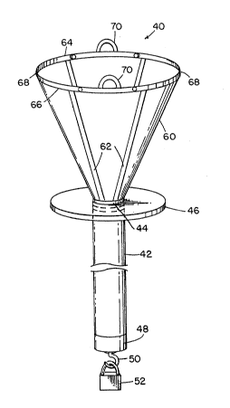
One embodiment of the packaging system for
endoscopes using disposable sheaths is illustrated in
Figure 2. A packaging bag 40 includes an elongated
insertion tube bag 42 having a length slightly longer
than the length of the insertion tube 12 of the endoscope
10 and a diameter that is substantially larger than the
diameter of the insertion tube 12 but within the range of
expansion of the sheath material. The insertion tube bag
42 is formed of a flexible but substantially nonelastic
material, such as a suitable plastic. The insertion tube
bag 42 is suspended from a rigid plastic collar 44 having
an outwardly projecting support flange 46. The insertion
tube bag 42 terminates in a rigid, cylindrical tip 48
having a hook 50 at its lower end from which a weight 52
is suspended. A funnel-like member 60 projects upwardly
from the collar 44. A plurality of relatively rigid
stays 62 can be attached to the funnel-like member 60.
The stays 62 extend upwardly from the collar 44 to a pair
relatively rigid peripheral rib~ 64, 66 which intersect
each other at a pair of hinge points 68. The hinge
points 68 allow the ribs 64, 66 to be folded against each
other to collapse the funnel-like member 60 flat to
reduce its size for shipping and storage. Also, securing
the ribs 64, 66 to each other causes the funnel-like
member 60 to assume the configuration of a bag for
housing the channels 20 (Figure 1) forming part of the
sheath 22 as well as other supplies and devices that may
:
' ~ - .
.
1 1
be used with the endo~cope 10 or sheath 22.
Alternatively, the funnel-like member 60 may be a
collapsible bag for holding various hoses prior to use.
The bag 60 may be removed or retracted prior to inserting
the endoscope into the sheath.
The funnel-like member 60 is preferably formed
from the same type of material as the insertion tube bag
42. However, for the reasons explained below, it may be
somewhat thinner. The stays 62 maintain the funnel-like
configuration of the funnel-like member 60. The
peripheral ribs 64, 66 are used to hold the periphery of
the funnel-like member 60 open for insertion and removal
of the insertion tube 12 of the endoscope 10. A pair of
semicircular tabs 70 project upwardly from the midpoints
of the peripheral ribs 64, 66. In the event a
collap~ible bag is used for member 60, the top edges of
the bag may be held up by support rack 200 from tabs 70,
by hooking members 202, as shown in Figure 7. This
latter design allows the user to raise and lower the bag
60 a9 desired. This can be helpful when integrating the
~heath to the endo~cope by allowing improved access. The
usèr mày wish the bag 60 to be held open and extended
upward while removing the hoses stored therein. The user
may then lower hooking member 202 by loosening clamp 201.
This lowers the top of the bag to the support arm 92 to
permit the user to directly access the nozzle 80 and
tubular bag opening.
As explained in greater detail below, the
packaging bag 40 is shipped with a disposable sheath (not
shown) extending along the length of the insertion tube
bag 42. The sheath is installed onto the inser-tion tube
12 by inserting the insertion tube 12 into the sheath
while the sheath is in the insertion tube bag 42. The
insertion tube 12 and sheath 22 are then removed from the
bag 42 for use in conducting an endoscopic procedure.
After the endoscopic procedure ha~ been completed, the
insertion tube 12, surrounded by the sheath 22, is
13~S9S3
12
inserted into the insertion tube bag 42, and the
insertion tube 12 is removed from the bag 42 while
leaving the sheath 22 behind in the insertion tube bag
42.
The manner of using the packaging bag 40 of
Figure 2 is explained in greater detail with reference to
Figure 3. The packaging bag 40 is illustrated in Figure
3A in the condition in which it i9 received from the
supplier of the sheath. The sheath 22 extends the length
of the insertion tube bag 42 from the cylindircal housing
25 to an inflation nozzle 80. The inflation nozzle 80
can be releasably secured to the bag 42 by conventional
means (not shown), such as a clip, snap or Velcro
fastener, to prevent inadvertent longitudinal movement of
the sheath 22 along the length of the bag 42. As
illustrated in Figure 3A, the diameter of the sheath 22
i8 substantially smaller than the diameter of the
insertion tube bag 42. In this condition, the insertion
tube bag 42 i~olates the sheath 22 from the environment
to avoid contamination and to maintain the sterility of
the ~heath 22.
The sheath 22 is installed on the insertion tube
12 of an endoscope, as illustrated in Figure 3B. A
conventional source of pressurized air is connected to an
inlet 82 of the nozzle 80 through a tube 84. Air thus
flows from inlet 82 into the interior of the sheath 22.
The nozzle 80 is made of nonexpandable material. The
nozzle 80 may be any suitable nozzle, such as the nozzle
shown in Patent No. 4,646,722. Since the end opening of
the nozzle 80 is blocked by the end of the insertion tube
12, the pressure in the sheath 22 builds up. The sheath
22 then expands until its outer surEace contacts the
inner surface of the insertion tube bag 42. The
insertion tube bag 42, by restraining expansion of the
sheath 22, reduces the necessity to precisely control
both the pressure applied to expand the sheath 22 and the
uniformity of the thickness of the sheath 22. If the
.,, ~ - ,
' - , '
:
.
,
13~9~3
~3
expansion of the sheath 22 was not prevented by the
insertion tube bag 42, excessive pressure applied to the
sheath 22 could cause the sheath 22 to burst like a
balloon. Also, irregularities in the thickness of the
wall of the sheath 22 could cause excessive or
insufficient expansion of the sheath 22 in localized
areas which could also cause the sheath 22 to rupture or
be difficult to use.
Once the sheath 22 has expanded to the diameter
of the insertion tube bag 42, the insertion tube 12 can
be easily further inserted into the sheath 22 through the
opening in the nozzle 80, as illustrated in Figure 3B.
After the insertion tube 12 has been inserted
all the way into the sheath 22, the air pressure is
removed from the nozzle 80 thereby allowing the sheath 22
to deflate. The tube 84 is then removed from the inlet
82 of the nozzle 80. The endoscope may then be used by
removing the insertion tube 12 and sheath 22 from the
insertion tube bag 42, as illustrated in Figure 3C.
Alternatively, the insertion tube 12 and sheath 22 may
remain in the insertion tube bag 42 until it is ready for
use. In this condition, the insertion tube bag 42 can
maintain the sterility or cleanliness of the sheath 22.
Also, of course, the insertion tube 12, surrounded by the
sheath 22, may be inserted into the bag 42 during an
endoscopic procedure or examination thereby storing the
endoscope in a manner that prevents the spread of
contamination in the examining room environment. This
may be desirable in the situation where the endoscope is
temporarily removed from the patient.
After the insertion tube 12 and sheath 22 have
been used to conduct an endoscopic procedure, the outer
surface of the sheath 22 as well as the channels 20 are
contaminated. It is important to prevent this
contamination from being spread around the examining room
environment as the sheath 22 is removed from the
insertion tube 12. The sheath 22 may be removed from the
. ~ .
13C~5953
14
insertion tube 12 without spreading contamination by
reinserting the insertion tube 12 and sheath 22 into the
insertion tube bag 42, as illustrated in Figure 3C. Air
pressure is then applied to the inlet 82 of the nozzle 80
5 through the tube 84 to inflate the sheath 22. The sheath
22 then expands away from the outer surface of the
insertion tube 12 against the inner surface of the
insertion tube bag 42, as illustrated in Figure 3B. Once
the sheath 22 has expanded to the diameter of the
insertion tube bag 42, the insertion tube 12 may be
removed from the sheath 22 with the same ease in which it
was installed, as illustrated in Figure 3B. The air
pressure is then removed from the sheath 22 to allow the
sheath 22 to deflate, as illustrated in Figure 3A. The
top of the bag assembly 40 is closed. The contaminated
~heath 22 c~n then be discarded with the insertion tube
bag 42 preventing the contamination from spreading to the
environment.
As mentioned above, the nonresilient
characteristic of the insertion tube bag 42 restricts
further expansion of the sheath 22 once the sheath
expands to the diameter of the bag 42. The bag 42
restricts expanYion of the sheath 22 during both the
insertion of the insertion tube 12 into the sheath 22 and
the removal of the insertion tube 12 from the sheath 22.
However, it is even more important to prevent an
explosive rupture of the sheath 22 during the removal of
the insertion tube 12 from the sheath 22 because an
explosive rupture of the sheath 22 during the removal
phase could spread contamination over a wide area. In
order to adequately restrict expansion of the sheath 22,
the bag 42 should be relatively sturdy. For typical,
commercially available plastic films, the bag 42 should
have a wall thickness of at least .004 inch of
polyethylene or other suitable material. In contrast,
since the funnel-like member 60 is not forced outwardly
:
~,-
.:
13~3~953
by inflation of the sheath 22, it may have a wall
thickness of about 0.001 inch to 0.002 inch.
The length of a typical insertion tube 12 is on
the order of 1 meter, and insertion tubes for
colonoscopes can have lengths of a~ long as 2 meters.
It can be difficult to support an insertion tube
bag 42 having a length of between 1 and 2 meters in a
vertical manner. Consequently, it may be desirable to
support the insertion tube bag 42 in a horizontal fashion
on table 301, as shown in Figure 6. In this embodiment,
the insertion tube bag 42 extends along table 301 between
a forked support rack 300 on a tab 302, and a hook 304.
The hook may be loaded with a suitable tensioning device
305 (spring or weight~ if desired, or may be a rigid
coupling.
For an endoscope with a length of 1 meter or
less, it may be desirable to use a stand 80 as
illustrated in Figures 4 and 7. This stand could extend
to the floor, as shown in Figure 4, or sit on a bench, as
shown in Figure 7. The elements and features of each are
interchangeable. The stand 80 includes a vertical
support bar 82 pro~ecting vertically from the base 79 or
from three legs 84 interconnected by a reinforcing ring
86. A clamp 88 includes a hand screw 90 for frictionally
engaging the support member 82 in a releasable manner. A
support arm 92 has a forked end 94 that supports the tube
40 at support flange 46, as shown in Figures 2 and 4.
Thus, the support arm 92 holds the collar 44 up through
the support flange 46. Alternatively, as shown in Figure
7, a collet closure 208 may be used to support collar 44
rather than using a forked member 94. When a large bag
is used without support ribs, it is sometimes
advantageous to retract the bag or funnel member below
the sheath manifold which extends just above support
collar 44 (not shown). Having the collet 208 extend
above support member 92 holds the collar 44 a desired
distance above member 92. This permits the bag member 60
.. .. .
~3~S~3S3
16
to be retracted below the top of the support collar 44
such as by folding bag 60 or by lowering clamp 200. This
improves acce~s to the sheath manifold (not shown) for
scope insertion and removal. A forked holder 96 project~
horizontally from support bar 82 above the support arm 92.
Member 60 allows the handle 14 (Figure 1) of the
endoscope to clip into the forked holder 96 while the
insertion tube 12 is left in the insertion tube bag 42
for subsequent use or disposal.
The weight 52, illustrated in Figures 2 and 4,
tensions the in~ertion tube bag 42 to prevent the sheath
22 from clinging to the bag 42 when the sheath 22 and
insertion tube 12 are being removed from or reinserted
into the bag 42. While the bag 42 is of an expandable
material, it may be made of collapsible material. A
weight of about 200 grams should be sufficiently heavy to
adequately anchor the end of the bag 42. Alternatively,
bag 42 may be a stiffer member and not require a weight.
The stand 80 illustrated in Figures 4 and 7 may
be advantageously used for endoscopes 10 having insertion
tubes 12 of up to about 1 meter. Endoscopes 10 having
longer insertion tubes 12 may require that the bag 42 by
positioned in an inclined or horizontal position on a
table, as shown in Figure 6. In this embodiment a
tension spring (not shown) extending between the distal
end of the insertion tube bag 42 and a fixed support may
; be used instead of the weight 52 to ensure that bag 42 is
completely extended.
In order to prevent contamination and/or
maintain the sterility of the sheath 22 prior to use and
to prevent damage while shipping, it is important to
package the packaging bag 40 for shipment and storage in
a suitable container. The substantial length of the
insertion tube bag 42 makes it undesirable to utilize a
;- 35 linear package for the packaging bag 40 since it is
difficult to transport and store relatively long objects.
Instead, the insertion tube bag 42 having sheath 22
.
.,, ,, . . ~ .
130S953
17
therein may be placed in a tray 100 of the type
illustrated in Figure 5. The tray lnO includes a
container 102 having a spiral recess 104 of a length and
width adapted to receive the insertion tube bag 42 in a
coiled configuration. A circular recess 106 formed at
the center of the container 102 receives the funnel-like
or bag member 60. The bag member 60 includes additional
hoses to be coupled to and disposed with sheath 22. The
container 102 may be covered by a paper or plastic
membrane sealed to the container 102 with a pressure-
sensitive adhesive. The packaging bag 40 can be
sterilized in the container 102 by suitable means, such
as by flooding the container 102 with ethylene oxide gas
When the sheath 22 is to be installed on the
lS insertion tube 12 of an endoscope, the paper or plastic
membrane can be peeled from the upper surface of the
container 102, thereby allowing the insertion tube bag 42
and funnel-like member 60 to be removed from the
respective recesses 104, 106. The packaging bag 40 is
then mounted at collar 44 on the stand 80 (Figure 4 or 7,
or table 301) and the weight 52 is attached to its lower
end. The insertion tube 12 is then inserted into the
sheath 22 as explained above with reference to Figure 3B.
After the sheath 22 has been installed on the insertion
tube 12, the insertion tube 12 and sheath 22 are removed
from the bag 42, and an endoscopic procedure or exam is
conducted. After the endoscopic procedure or exam has
been completed, the insertion tube 12 and sheath 22 are
reinserted into the insertion tube bag 42, the sheath 22
i~ inflated and the insertion tube 12 is then removed
from the sheath 22. The contaminated sheath 22 inside
the insertion tube bag 42 can then be disposed of either
directly or after once again placing the insertion tube
bag 42 and funnel-like member 60 in the respective
recesses 104, 106 of the tray 100.
Is is thus seen that the inventive packaging
system prevents the sheath from becoming contaminated
~.,
- ~3C~S9S3
]8
prior to use, and it prevents the spread of contamination
as the sheath is being removed from the endoscope after
use and during disposal of the contaminated sheath. The
bag further facilitates the installation of the sheath on
the endoscope and the removal of the sheath from the
endoscope after use. Further, the packaging system can
be easily adapted for use with endoscope sheaths having a
wide variety of shapes and sizes and special functioning
designs.
"
:,,
: 35
' ,:
::,
,,1
..,
.
,
~ ,